Unit - 3
Projections of Straight Lines and Planes and their Traces
A straight line is the shortest distance between two points. Hence, the projections
Of a straight line may be drawn by joining the respective projections of its ends
Which are points.
Line Parallel to one or both the planes:
(a) Line AB is parallel to the H.P.
a and b are the top views of the ends A and B respectively. It can be clearly seen that the figure ABba is a rectangle. Hence, the top view ab is equal to AB. a'b' is the front view of AB and is parallel to xy.
(b) Line CD is parallel to the V.P.
The line c'd' is the front view and is equal to CD; the top view cd is parallel to xy.
(c) Line ff is parallel to the H.P. And the V.P.
Ef is the top view and e'f' is the front view; both are equal to ff and parallel to xy.
Hence, when a line is parallel to a plane, its projection on that plane is equal to its true length, while its projection on the other plane is parallel to the reference line.
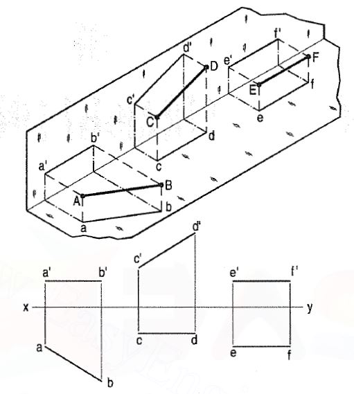
Figure 1
Line perpendicular to one of the planes:
When a line is perpendicular to one reference plane, it will be parallel to the other.
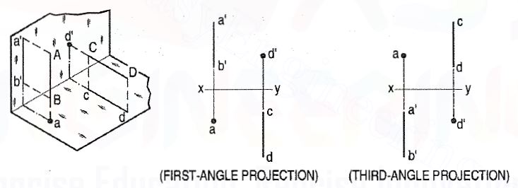
Figure 2
(a) Line AB is perpendicular to the H.P. The top views of its ends coincide in the point a. Hence, the top view of the line AB is the point a. Its front view a' b' is equal to AB and perpendicular to xy.
(b) Line CO is perpendicular to the V.P. The point d' is its front view and the line cd is the top view. Cd is equal to CO and perpendicular to xy.
Hence, when a line is perpendicular to a plane its projection on that plane is
a point, while its projection on the other plane is a line equal to its true length and
Perpendicular to the reference line.
In first-angle projection method, when top views of two or more points coincide,
The point which is comparatively farther away from xy in the front view will be
Visible; and when their front views coincide, that which is farther away from xy in
The top view will be visible.
In third-angle projection method, it is just the reverse. When top views of two
Or more points coincide the point which is comparatively nearer xy in the front
View will be visible; and when their front views coincide, the point which is nearer xy in the top view will be visible.
The inclination of a line to a plane is the angle which the line makes with its
Projection on that plane.
(a) Line PQ1 [fig. 3(i)] is inclined at an angle 8 to the H.P. And is parallel
To the V.P. The inclination is shown by the angle 8 which PQ1 makes with
Its own projection on the H.P., viz. The top view pq1•
The projections [fig. 3(ii)] may be drawn by first assuming the line to
Be parallel to both the H.P. And the V.P. Its front view p’q’ and the top
View pq will both be parallel to xy and equal to the true length. When the
Line is turned about the end P to the position PQ1 so that it makes the
Angle 8 with the H.P. While remaining parallel to the V.P., in the front view
The point q’ will move along an arc drawn with p’ as centre and p’q’ as
Radius to a point q’1 so that p’q’ 1 makes the angle 8 with xy. In the top
View, q will move towards p along pq to a point q1 on the projector
Through q’1• p’q’1 and pq1 are the front view and the top view respectively
Of the line PQ1.
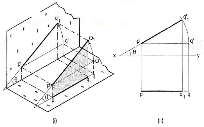
Figure 3
Line inclined to both the planes:
(a) A line AB (fig. 4) is inclined at θ to the H.P. And is parallel to the V.P. The end A is in the H.P. AB is shown as the hypotenuse of a right-angled triangle, making the angle θ with the base.
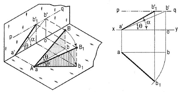
Figure 4
The top view ab is shorter than AB and parallel to xy. The front view a'b' is equal to AB and makes the angle θ with xy.
Keeping the end, A fixed and the angle θ with the H.P. Constant, if the end B is moved to any position, say B1, the line becomes inclined to the V.P. Also.
In the top view, b will move along an arc, drawn with a as centre and ab as radius, to a position b1. The new top view ab1 is equal to ab but shorter than AB.
In the front view, b' will move to a point b'1 keeping its distance from xy constant and equal to b'o; i.e. it will move along the line pq, drawn through b' and parallel to xy. This line pq is the locus or path of the end 8 in the front view. b'1 will lie on the projector through b1• The new front view a'b'1 is shorter than a'b' (i.e. AB) and makes an angle a with xy. A is greater than θ.
Thus, if the inclination θ of AB with the H.P. Is constant, even when it is inclined to the V.P.
(i) its length in the top view, viz. Ab remains constant; and
(ii) the distance between the paths of its ends in the front view, viz. b'o remains constant.
(b) The same line AB (fig. 5) is inclined at θ to the V.P. And is parallel to the H.P. Its end A is in the V.P. AB is shown as the hypotenuse of a right-angled triangle making the angle θ with the base.
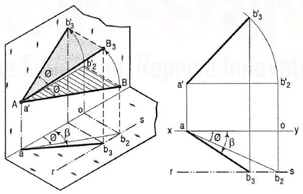
Figure 5
The front view a'b'2 is shorter than AB and parallel to xy. The top view ab2 is equal to AB and makes an angle φ with xy.
Keeping the end, A fixed and the angle φ with the V.P. Constant, if B is moved to any position, say B3, the line will become inclined to the H.P. Also. In the front view, b'2, will move along the arc, drawn with a' as centre and a'b'2 as radius, to a position b' 3• The new front view a'b'3 is equal to a'b'2 but is shorter than AB.
Hence, when a line is inclined to both the planes, its projections are shorter than the true length and inclined to xy at angles greater than the true inclinations. These angles viz. α and β are called apparent angles of inclination.
Projection of lines inclined to both the planes:
As long as the inclination of AB with the H.P. Is constant
(i) its length in the top view, viz. Ab remains constant, and
(ii) in the front view, the distance between the loci of its ends, viz. b'o remains
Constant.
In other words, if
(i) its length in the top view is equal to ab, and
(ii) the distance between the paths of its ends in the front view is equal to b'o,
The inclination of AB with the H.P. Will be equal to e. Similarly, we find that if the inclination of AB with the V.P. Is constant.
(i) its length in the front view, viz. a'b'2 remains constant, and
(ii) in the top view, the distance between the loci of its ends, viz. b2o remains
Constant.
The reverse of this is also true, viz.
(i) if its length in the front view is equal to a'b'2, and
(ii) the distance between the paths of its ends in the top view is equal to b2o, the
Inclination of AB with the V.P. Will be equal to 0.
Combining the above two findings, we conclude that when AB is inclined at e
To the H.P. And at 0 to the V.P.
(i) its lengths in the top view and the front view will be equal to ab2 and a'b'2
Respectively, and
(ii) the distances between the paths of its ends in the front view and the top view
Will be equal to b'2o and b2o respectively.
When a line is inclined to a plane, it will meet that plane, produced if necessary.
The point in which the line or line-produced meets the plane is called its trace.
The point of intersection of the line with the H.P. Is called the horizontal trace,
Usually denoted as H.T. And that with the V.P. Is called the vertical trace or V.T.
Refer to fig. 6.
(i) A line AB is parallel to the H.P. And the V.P. It has no trace.
(ii) A line CD is inclined to the H.P. And parallel to the V.P. It has only the H.T. But no V.T.
(iii) A line ff is inclined to the V.P. And parallel to the H.P. It has only the V.T. But no H.T.
Thus, when a line is parallel to a plane it has no trace upon that plane. Refer to fig. 7.
(i) A line PQ is perpendicular to the H.P. Its H.T. Coincides with its top view which is a point. It has no V.T.
(ii) A line RS is perpendicular to the V.P. Its V.T. Coincides with its front view
Which is a point. It has no H.T.
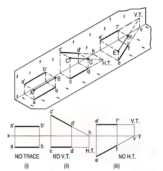
Figure 6
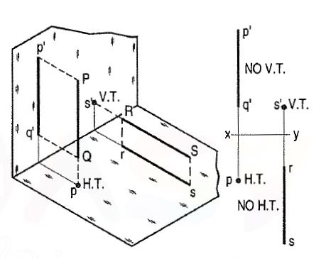
Figure 7
Hence, when a line is perpendicular to a plane, its trace on that plane coincides with its projection on that plane. It has no trace on the other plane. Refer to fig. 8.
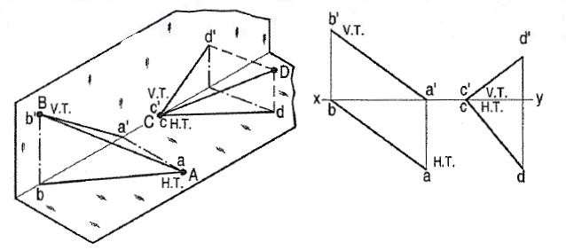
Figure 8
(i) A line AB has its end A in the H.P. And the end B in the V.P. Its H.T. Coincides with the top view of A and the V.T. Coincides with b' the front view of B.
(ii) A line CD has its end C in both the H.P. And the V.P. Its H.T. And V.T. Coincide with c and c' (the projections of C) in xy. Hence, when a line has an end in a plane, its trace upon that plane coincides with the projection of that end on that plane.
Plane figures or surfaces have only two dimensions, viz. Length and breadth. They do not have thickness. A plane figure may be assumed to be contained by a plane, and its projections can be drawn, if the position of that plane with respect to the principal planes of projection is known.
Planes may be divided into two main types:
(1) Perpendicular planes.
(2) Oblique planes.
(1) Perpendicular planes: These planes can be divided into the following sub-types:
(i) Perpendicular to both the reference planes.
(ii) Perpendicular to one plane and parallel to the other.
(iii) Perpendicular to one plane and inclined to the other.
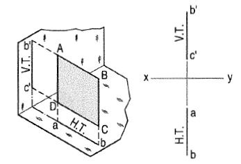
(i) Perpendicular to both the reference planes:
A square ABCD is perpendicular to both the planes. Its H.T. And V.T. Are in a straight line perpendicular to xy.
The front view b'c' and the top view ab of the square are both lines coinciding with the V.T. And the H.T. Respectively.
Ii) Perpendicular to one plane and parallel to other:
a) Plane, perpendicular to the H.P. And parallel to the V.P. [fig. 9(i)].
A triangle PQR is perpendicular to the H.P. And is parallel to the V.P. Its
H.T. Is parallel to xy. It has no V.T.
The front view p'q'r' shows the exact shape and size of the triangle. The
Top view pqr is a line parallel to xy. It coincides with the H.T.
(b) Plane, perpendicular to the V.P. And parallel to the H.P. [fig. 9(ii)].
A square ABCD is perpendicular to the V.P. And parallel to the H.P. Its V.T.
Is parallel to xy. It has no H.T.
The top view abed shows the true shape and true size of the square. The front
View a'b' is a line, parallel to xy. It coincides with the V.T.
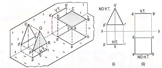
Figure 9
Perpendicular to one plane and inclined to the other plane:
(a) Plane, perpendicular to the H.P. And inclined to the V.P. (fig. 10).
A square ABCD is perpendicular to the H.P. And inclined at an angle φ to
The V.P. Its V.T. Is perpendicular to xy. Its H.T. Is inclined at φ to xy.
Its top view ab is a line inclined at φ to xy. The front view a'b'c'd' is
Smaller than ABCD.
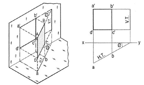
Figure 10
(b) Plane, perpendicular to the V.P. And inclined to the H.P. (fig. 11).
A square ABCD is perpendicular to the V.P. And inclined at an angle θ to
The H.P. Its H.T. Is perpendicular to xy. Its V.T. Makes the angle e with
Xy. Its front view a'b' is a line inclined at θ to xy. The top view abed is
a rectangle which is smaller than the square ABCD.
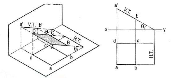
Figure 11
Reference/Text Books
1. N. D. Bhatt, Engineering Drawing, Charotar Publishing House, 46th Edition, 2003.
2. K. V. Nataraajan, A text book of Engineering Graphic, Dhanalakshmi Publishers, Chennai, 2006.
3. K. Venugopal and V. Prabhu Raja, Engineering Graphics, New Age International (P) Ltd, 2008.
4. Dhananjay A. Jolhe, Engineering Drawing with an Introduction to Autocad, McGraw Hill Education, 2017