Unit - 4
Projections of Solids
Solids may be divided into two main groups:
(1) Polyhedra
(2) Solids of revolution.
Polyhedra: A polyhedron is defined as a solid bounded by planes called faces. When all faces are equal and regular, the polyhedron is said to be regular. There are seven regular polyhedra which may be defined as stated below:
(i) Tetrahedron (fig.): It has four equal faces, each an equilateral triangle.
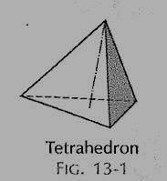
Figure
(ii) Cube or hexahedron (fig.): It has six faces, all equal squares.
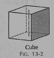
Figure
(iii) Octahedron (fig.): It has eight equal equilateral triangles as faces.
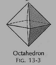
Figure
(iv) Dodecahedron (fig.): It has twelve equal and regular pentagons as faces.
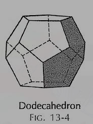
Figure
(v) Icosahedron (fig.): It has twenty faces, all equal equilateral triangles.
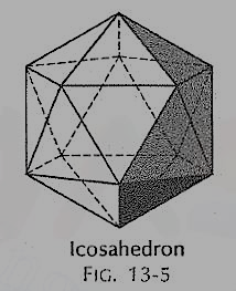
Figure
(vi) Prism: This is a polyhedron having two equal and similar faces called its ends or bases, parallel to each other and joined by other faces which are parallelograms. The imaginary line joining the centres of the bases is called the axis. A right and regular prism (fig.) has its axis perpendicular to the bases. All its faces are equal rectangles.
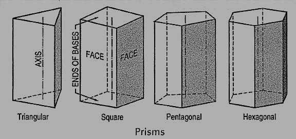
Figure
(vii) Pyramid: This is a polyhedron having a plane figure as a base and many triangular faces meeting at a point called the vertex or apex. The imaginary line joining the apex with the centre of the base is its axis.
A right and regular pyramid (fig.) has its axis perpendicular to the base which is a regular plane figure. Its faces are all equal isosceles triangles.
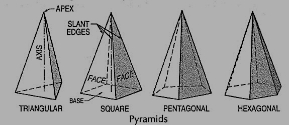
Figure
Oblique prisms and pyramids have their axes inclined to their bases. Prisms and pyramids are named according to the shape of their bases, as triangular, square, pentagonal, hexagonal etc.
A triangular prism1 base 40 mm side and height 65 mm is resting on the H.P. On one of its rectangular faces with the axis parallel to the V.P. Draw its projections.
As the axis is parallel to both the planes, begin with the side view.
(i) Draw an equilateral triangle representing the side view, with one side in xy.
(ii) Project the front view horizontally from this triangle.
(iii) Project down the top view from the front view and the side view, as shown.
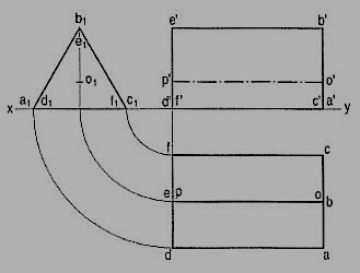
Figure
Problems:
Draw the projections of the following solids, situated in their respective positions, taking a side of the base 40 mm long or the diameter of the base 50 mm long and the axis 65 mm long.
1. A hexagonal pyramid, base on the H.P. And a side of the base parallel to and 25 mm in front of the V.P.
2. A square prism, base on the H.P., a side of the base inclined at 30° to the V.P. And the axis 50 mm in front of the V.P.
3. A triangular pyramid, base on the H.P. And an edge of the base inclined at 45° to the V.P.; the apex 40 mm in front of the V.P.
Projections of solids with axis inclined to one of the reference planes and parallel to the other:
When a solid has its axis inclined to one plane and parallel to the other, its projections are drawn in two stages.
(1) In the initial stage, the solid is assumed to be in simple position, i.e. its axis perpendicular to one of the planes.
If the axis is to be inclined to the ground, i.e. the H.P., it is assumed to be perpendicular to the H.P. In the initial stage. Similarly, if the axis is to be inclined to the V.P., it is kept perpendicular to the V.P. In the initial stage.
Moreover
(i) if the solid has an edge of its base parallel to the H.P. Or in the H.P. Or on the ground, that edge should be kept perpendicular to the V.P.; if the edge of the base is parallel to the V.P. Or in the V.P., it should be kept perpendicular to the H.P.
(ii) If the solid has a corner of its base in the H.P. Or on the ground, the sides of the base containing that corner should be kept equally inclined to the V.P.; if the corner is in the V.P., they should be kept equally inclined to the H.P.
When a solid has its axis inclined to one plane and parallel to the other, its
Projections are drawn in two stages.
(1) In the initial stage, the solid is assumed to be in simple position, i.e. its
Axis perpendicular to one of the planes.
If the axis is to be inclined to the ground, i.e. the H.P., it is assumed
To be perpendicular to the H.P. In the initial stage. Similarly, if the axis is to
Be inclined to the V.P., it is kept perpendicular to the V.P. In the initial stage.
Moreover
(i) if the solid has an edge of its base parallel to the H.P. Or in the H.P.
Or on the ground, that edge should be kept perpendicular to the V.P.;
If the edge of the base is parallel to the V.P. Or in the V.P., it should
Be kept perpendicular to the H.P.
(ii) If the solid has a corner of its base in the H.P. Or on the ground,
The sides of the base containing that corner should be kept equally
Inclined to the V.P.; if the corner is in the V.P., they should be kept
Equally inclined to the H.P.
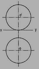
The projection of a sphere in any position on any plane is always a circle whose diameter is equal to the diameter of the sphere (fig. 13-48). This circle represents the contour of the sphere.
Figure
A flat circular surface is formed when a sphere is cut by a plane. A hemisphere (i.e. a sphere cut by a plane passing through its center) has a flat circular face of diameter equal to that of the sphere.
When it is placed on the ground on its flat face, its front view is a semi-circle, while its top view is a circle [fig.].
When the flat face is inclined to the H.P. Or the ground and is perpendicular to the V.P. It is an ellipse (partly hidden) in the top view [fig], while the contour of the hemisphere is shown by the arc of the circle drawn with radius equal to that of the sphere.
Fig shows the projections of a sphere, a small portion of which is cut off by a plane. Its flat face is perpendicular to the H.P. And inclined to the V.P. An ellipse is seen in the front view within the circle for the sphere.
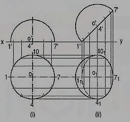
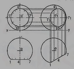
Figure Figure
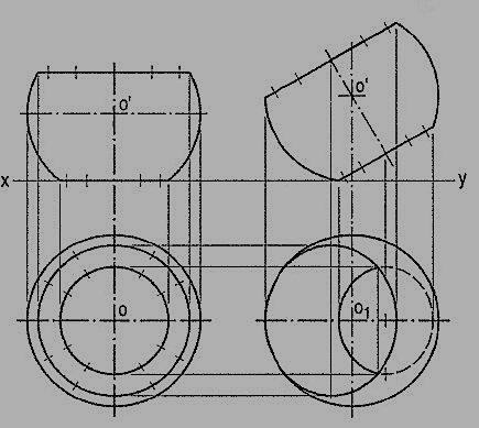
When the flat face of a cut sphere is perpendicular to the V.P. And inclined to the H.P., its projections can be drawn as described in below problem.
1. A brass flower-vase is spherical in shape with flat, circular top 35 cm diameter and bottom 25 cm diameter and parallel to each other. The greatest diameter is 40 cm. Draw the projections of the vase when its axis is parallel to the V.P. And makes an angle of 60° with the ground. (fig. 24)
(i) Draw the front view of the vase resting on its bottom with its axis vertical. Project the top view.
(ii) Tilt the front view so that the axis makes 60° angle with xy and project the top view. Note that a part of the ellipse for the bottom is also visible.
Figure
Spheres in contact with each other:
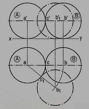
Projections of two equal spheres resting on the ground and in contact with each other, with the line joining their centres parallel to the V.P., are shown in fig. 25.
Figure
As the spheres are equal in size, the line joining their centres is parallel to the ground also. Hence, both ab and a'b' show the true length of that line (i.e. equal to the sum of the two radii or the diameter of the spheres). The point of contact between the two spheres is also visible in each view.
If the position of one of the spheres, say sphere B, is changed so that the line joining their centres is inclined to the V.P., in the front view, the centre b' will move along the line a'b' to b'1. The true length of the line joining the centres and the point of contact are now seen in the top view only.
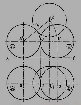
When the sphere B is so moved that it remains in contact with the sphere A and the line joining their centres is parallel to the V.P., but inclined to the ground (fig.),the true length of that line and the point of contact are visible in the front view only.
Figure
Problem:
Three equal spheres of 38 mm diameter are resting on the ground so that each touches the other two and the line joining the centres of two of them is parallel to the V.P.
A fourth sphere of 50 mm diameters placed on top of the three spheres to form a pile. Draw three views of the arrangement and find the distance of the centre of the fourth sphere above the ground.
As the spheres are resting on the ground and are equal in size, the lines joining their centres will be parallel to the ground. In the top view, the centres will lie at the corners of an equilateral triangle of sides equal to the sum of the two radii, i.e. 40 mm.
Draw (in the top view) an equilateral triangle abc of 40 mm long sides with oneside, say ab, parallel to xy. At its corners, draw three circles of 40 mm diameter.Project the front view. The centres will lie on a line parallel to and 20 mm above xy.
When the fourth sphere is placed on top, its centre d in the top view will bein the centre of the triangle. In the front view, it will lie on a projector through d.The true distance between the centreof the top sphere and that of any one of the bottomspheres will be equal to the sum of the two radii, viz. 20 mm + 25 mm, i.e. 45 mm.
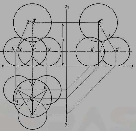
But as none of the lines da, db or de is parallel to xy, their front views will not show their true lengths. Therefore, to locate the position of the centre of thetop sphere in the front view,
(i) make one of the lines, say da, parallel to xy;
(ii) project a1 to a'1 on the path of a' and
(iii) with a'1 as centre and radius equal to 45 mm, draw an arc cutting theprojector through d at the required point d'. With d' as centre and radiusequal to 25 mm, draw the required circle which will be partly hidden asshown. h is the distance of the centre of the sphere from the ground.
(iv) Project the side view. As c'd' is parallel to the new reference line, c"d"will be equal to 45 mm and the point of contact p' between the sphereshaving centres c and d will be visible.
Reference/Text Books
1. N. D. Bhatt, Engineering Drawing, Charotar Publishing House, 46th Edition, 2003.
2. K. V. Nataraajan, A text book of Engineering Graphic, Dhanalakshmi Publishers, Chennai, 2006.
3. K. Venugopal and V. Prabhu Raja, Engineering Graphics, New Age International (P) Ltd, 2008.
4. Dhananjay A. Jolhe, Engineering Drawing with an Introduction to Autocad, McGraw Hill Education, 2017