Unit - 5
Sectioning of Solids, Isometric Projections
Invisible features of an object are shown by dotted lines in their projected views. But when such features are too many, these lines make the views more complicated and difficult to interpret. In such cases, it is customary to imagine the object as being cut through or sectioned by planes. The part of the object between the cutting plane and the observer is assumed to be removed and the view is then shown in section.
The imaginary plane is called a section plane or a cutting plane. The surface produced by cutting the object by the section plane is called the section. It is indicated by thin section lines uniformly spaced and inclined at 45°.
The projection of the section along with the remaining portion of the object is called a sectional view. Sometimes, only the word section is also used to denote a sectional view.
(1) Section planes:
Section planes are generally perpendicular planes. They may be perpendicular to one of the reference planes and either perpendicular, parallel or inclined to the other plane. They are usually described by their traces. It is important to remember that the projection of a section plane, on the plane to which it is perpendicular, is a straight line. This line will be parallel, perpendicular or inclined to xy, depending upon the section plane being parallel, perpendicular or inclined respectively to the other reference plane.
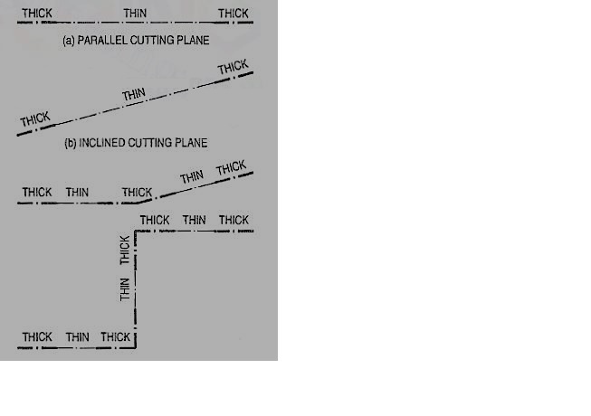
Figure 1
As per latest 8.1.S. Convention (SP: 46-2003), the cutting-plane line should be drawn as shown in fig. 1.
(2) Sections: The projection of the section on the reference plane to which the section plane is perpendicular, will be a straight-line coinciding with the trace of the section plane on it. Its projection on the other plane to which it is inclined is called apparent section. This is obtained by
(i) projecting on the other plane, the points at which the trace of the section plane intersects the edges of the solid and
(ii) drawing lines joining these points in proper sequence.
(3) True shape of a section: The projection of the section on a plane parallel to the section plane will show the true shape of the section. Thus, when the section plane is parallel to the H.P. Or the ground, the true shape of the section will be seen in sectional top view. When it is parallel to the V.P., the true shape will be visible in the sectional front view.
But when the section plane is inclined, the section must be projected on an auxiliary plane parallel to the section plane, to obtain its true shape. When the section plane is perpendicular to both the reference planes, the sectional side view will show the true shape of the section. In this chapter sections of different solids are explained in stages by means of typical problems as follows:
1. Sections of prisms
2. Sections of pyramids
3. Sections of cylinders
4. Sections of cones
5. Sections of spheres.
As all the edges of the cube are equally foreshortened, the square faces are rhombuses. The rhombus ABCD (fig. 2) shows the isometric projection ofthe top square face of the cube in which BO is the true length of the diagonal.
Construct a square BQDP around BO as a diagonal. Then BP shows the truelength of BA.
In triangle ABO, 
In triangle PBO, 

The ratio,  .
.
Thus, the isometric projection is reduced in the ratio  , i.e. the isometric lengths are 0.815 of the true lengths.
Therefore, while drawing an isometric projection, it is necessary to convert true lengths into isometric lengths for measuring and marking the sizes. This is conveniently done by constructing and making use of an isometric scale as shown below.
a) Draw a horizontal line BO of any length (fig.). At the end B, draw lines BA and BP, such that L OBA = 30° and L OBP = 45°.Mark divisions of true length on the line BP and from each division-point, draw verticals to BO meeting BA at respective points. The divisions thus obtained on BA give lengths on isometric scale.
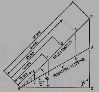
Figure
(b) The same scale may also be drawn with divisions of natural scale on a horizontal line AB (fig.). At the ends A and B, draw lines AC and BC making 15° and 45° angles with AB respectively, and intersecting each other at C.
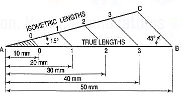
Figure
From division-points of true lengths on AB, draw lines parallel to BC and meeting AC at respective points. The divisions along AC give lengths to isometric scale.
The lines BO and AC (fig.) represent equal diagonals of a square face of the cube, but are not equally shortened in isometric projection. BO retains its true length, while AC is considerably shortened. Thus, it is seen that lines which are not parallel to the isometric axes are not reduced according to any fixed ratio. Such lines are called non-isometric lines. The measurements should, therefore, be made on isometric axes and isometric lines only. The non-isometric lines are drawn by locating positions of their ends on isometric planes and then joining them.
The orthographic view of a sphere seen from any direction is a circle of diameter equal to the diameter of the sphere. Hence, the isometric projection of a sphere is also a circle of the same diameter as explained below.
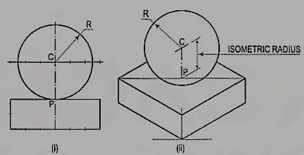
The front view and the top view of a sphere resting on the ground are shown in fig. C is its centre, D is the diameter and P is the point of its contact with the ground.
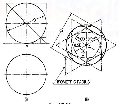
Figure
Assume a vertical section through the centre of the sphere. Its shape will bea circle of diameter D. The isometric projection of this circle is shown in fig. 25 (ii)by ellipses 1 and 2, drawn in two different vertical positions around the same centre C. The length of the major axis in each case is equal to D. The distance of the point P from the centre C is equal to the isometric radius of the sphere.
Again, assume a horizontal section through the centre of the sphere. The isometric projection of this circle is shown by the ellipse 3, drawn in a horizontal position around the same centre C. In this case also, the distance of the outermost points on the ellipse from the centre C is equal to O.5D.
Thus, in an isometric projection, the distances of all the points on the surface of a sphere from its centre, are equal to the radius of the sphere.
Hence, the isometric projection of a sphere is a circle whose diameter is equal to the true diameter of the sphere.
Also, the distance of the centre of the sphere from its point of contact with the ground is equal to the isometric radius of the sphere, viz. CP.
It is, therefore, of the utmost importance to note that, isometric scale must invariably be used, while drawing isometric projections of solids in conjunction with spheres or having spherical parts.
Problem:
Draw the isometric projection of a sphere resting centrally on the top of a square prism, the front view of which is shown in fig.
Figure
(i) Draw the isometric projection (using isometric scale) of the square prism and locate the centre P of its top surface [fig. 26 (ii)].
(ii) Draw a vertical at P and mark a point C on it, such that PC = the isometric radius of the sphere.
(iii) With C as centre and radius equal to the radius of the sphere, draw a circle which will be the isometric projection of the sphere.
Reference/Text Books
1. N. D. Bhatt, Engineering Drawing, Charotar Publishing House, 46th Edition, 2003.
2. K. V. Nataraajan, A text book of Engineering Graphic, Dhanalakshmi Publishers, Chennai, 2006.
3. K. Venugopal and V. Prabhu Raja, Engineering Graphics, New Age International (P) Ltd, 2008.
4. Dhananjay A. Jolhe, Engineering Drawing with an Introduction to Autocad, McGraw Hill Education, 2017