Unit 1
Oscillation, Ultrasonic and Dielectric Materials
Definition- A system is said to execute free oscillations if on being disturbed from its position of equilibrium, it oscillates itself without outside interference
When a simple pendulum is displaced from its position of equilibrium and left to itself, it starts oscillating with a definite time period depending upon its length and the acceleration due to gravity. This is called free oscillations.
In free oscillation amplitude and period remains constant without any external. Ideally, free oscillation does not undergo damping but practically it is not possible. As in all-natural systems damping is observed unless and until any constant external force is supplied to overcome damping.
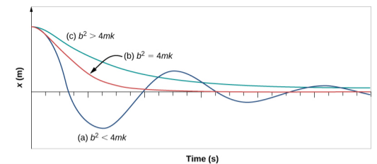
We know that in reality, a spring won't oscillate for ever. Frictional forces will diminish the amplitude of oscillation until eventually the system is at rest.
We will now add frictional forces to the mass and spring. Imagine that the mass was put in a liquid like molasses. Your lab instructor will not like it when they see their nice metal weight coated with a thick layer of ants in the morning. Be that as it may, when the mass is inside the molasses, it'll hardly oscillate at all.
On the other hand, a mass in air oscillates many times before it comes to rest. To incorporate friction, we can just say that there is a frictional force that's proportional to the velocity of the mass. This is a pretty good approximation for a body moving at a low velocity in air, or in a liquid. So we say the frictional force  . The constant
  depends on the kind of liquid the mass is in and the shape of the mass. The negative sign, just says that the force is in the opposite direction to the body's motion. Let's add this frictional force in to the equation
 |
Definition- A system is said to execute forced oscillations when it is compelled or forced to oscillate with a frequency other than its natural frequency.
We have learnt that the amplitude of the oscillations of a system or a body executing damped simple harmonic oscillator goes on decreasing and ultimately vanish with the passage of time. The oscillation of such a body can be maintained by applying an external periodic force.
When a body oscillates by being influenced by an external periodic force, it is called forced oscillation. Here, the amplitude of oscillation, experiences damping but remains constant due to the external energy supplied to the system.
For example – A child’s swing comes to rest unless external force applied at proper and regular interval of time to make the swing keep on swinging with a large amplitude. The same is the case with a pendulum or a vibrating mass attached to a spring. The applied periodic force is called the Driving Force and the oscillating system is called the Driven Oscillator. The oscillations of the driven oscillators are called Forced Oscillations.
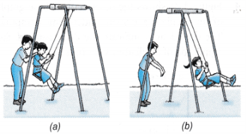
Resonance occurs when:-
Frequency of the external periodic force = Natural frequency of the system.
Definition:- The phenomena of producing oscillatory motion in a system by the influence of an external periodic force having the same frequency as that of natural frequency of the system is called Resonance.
Example:- Resonance causes disaster during earthquake. When the natural frequency of the building becomes equal to the frequency of the periodic vibration present in the earth during earthquake, then the building starts vibrating with large amplitude and hence it collapses.
Consider a body of mass m attached to one end of the spring whose other end is fixed rigidly. Let an external periodic force Fe(t)=F0cosωet is applied to the body to displace it from its mean position.
Fo= Amplitude of external force
ωe= Angular frequency of external periodic force
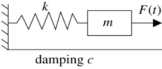
With the external force Fe(t) other forces are also acting on oscillators we named it as f1 and f2.
f1= Restoring Force = -kx where k is spring constant and x is displacement. You are thinking of this negative sign. Here Negative sign indicates restoring force acting in opposite direction of the displacement.
f2 = Frictional Force = -bv = -b  = -b
= -b
Total Force F= f1 + f2.+ Fe(t)
F=-kx –b (  ) + F0cosωet …..(1)
We know by newton’s law F=ma =m (d2x/ d2y) = m ……(2)
……(2)
Note- Derivative express as dot on it as written above
m (d2x/ d2y) = -kx –b (  ) + F0cosωet
m (d2x/ d2y) +kx +b (  ) = F0cosωet
Dividing both sides by m, we get
(d2x/ d2y) + x +
x + (
(  ) =
) =  cos ωet
Or  +
+  +
+ x =
x =  cos ωet ……(3)
Which is the Differential Equation of Forced Oscillator.
The solution of above (3) eq is given by
x= Xm cos (ωet- ϕ)
Xm=amplitude of forced oscillator and it is given by
Xm=F0/{m2(ω2-ωe2)2+b2ωe}1/2 …….(4)
 =bωe/m(ω2-ωe2)
If damping constant is very small then b2 can be neglected so
Xm= F0/ m(ω2-ωe2) …….(5)
Amplitude of forced oscillator is maximum when ω=ωe where ω is natural frequency (from eq 4)
Xm= F0/ bωe = F0/ bω
In the absence of damping constant b the maximum amplitude of the forced oscillator at ω=ωe So Xm= ∞
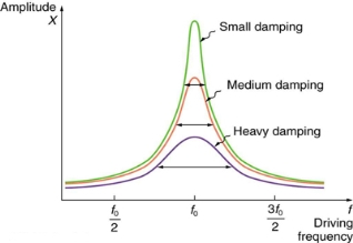
In figure f0 is frequency = ω=ωe in case of resonance as predicted in figure we obtain maximum amplitude at f0= = ω/2 =ωe/2
=ωe/2 .
.
Ultra (meaning beyond) + sonic (meaning sound) = beyond the audible sound range i.e. 20kHZ
As we know Sound wave is a vibration that can be transmitted through a medium like air, water, and metals. Whereas Ultrasonic wave is defined as inaudible sound with high frequency of range more than 20 kHz which is actually higher than the upper audible limit of human hearing.A healthy body can hear soundwave of frequency approximately 20 kilohertz. Also this range can vary from human to human.
In other words Sound wave which is not intended to be heard by human is also called ultrasonic wave.
Generally these waves are called as high frequency waves
Properties
a) The ultrasonic waves cannot travel through vacuum.
b) These waves travel with speed same as sound wave travel in any given medium.
c) In homogeneous medium the velocity of ultrasonic wave is constant.
d) These waves can also weld some material like plastics and metals.
e) They have high energy content.
f) Ultrasonic waves get reflected, refracted and absorbed just like sound waves.
g) They can be transmitted over large distances without any appreciable loss of energy.
h) They produce intense heating effect when passed through a substance.
i) The ultrasonic waves have high frequency.
j) Because of their smaller wavelength Ultrasonic waves produce negligible diffraction effects.
k) Ultrasonic waves can produce vibrations in low viscosity liquids.
l) When the ultrasonic wave is absorbed by a medium, it produces heat because of high frequency and high energy and that energy is used to drill and cut thin metals.
Ultrasonic waves are produced by the following methods.
(1) Magneto-striction generator or oscillator
(2) Piezo-electric generator or oscillator
Principle: Magnetostriction effect: Magnetostriction is a property of magnetic materials like nickel or iron that causes them to change their shape or dimensions during the process of magnetization. i.e. when these material is placed in magnetic field parallel to its length it undergoes changes in its dimensions. This is called Magnetostriction effect.
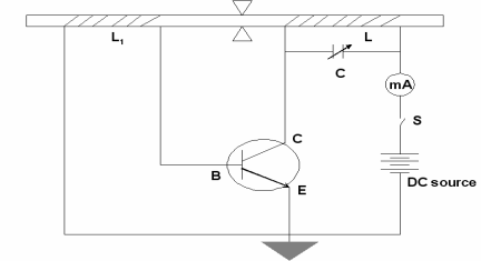
Figure
Construction
In above figure we are using NPN Transistor
In which battery is connected in such a way that emitter is forward biased and collector is reverse biased.
Current can be produced by applying necessary biasing to the transistor with the help of the battery.
The current produced in a circuit can be noted by the mill ammeter connected across the coil L.
The ends of the ferromagnetic rod A and B is wound by the coils L1 and L.
The coil L1 is connected to the base of NPN transistor The coil L is connected to the collector of the NPN transistor as shown in the figure.
The frequency of the oscillatory circuit (LC) can be adjusted by the condenser C.
Working
The rod is initially magnetized by the DC power supply. The transistor is properly biased. The battery is switched on and hence current is produced by the transistor. This current is passed through the coil L, this current causes a change in the magnetization of the rod. Now, the rod starts vibrating due to Magnetostriction effect.
When rod is vibrating and the coil is wounded over a vibrating rod, An emf is induced in coil L, this induces an emf to coil L1 & a part of it is feed as input to the base. Hence, this feedback system makes transistor operates continuously. The e.m.f. Induced in the coil called as converse Magnetostriction effect. In this way the current is maintained in transistor so as the vibrations.
The frequency of the oscillatory circuit is adjusted by the condenser C and when this frequency is equal to the frequency of the vibrating rod, resonance occurs. At resonance, the rod vibrates longitudinally with larger amplitude producing ultrasonic waves of high frequency along both ends of the rod.
Condition for resonance
Frequency of the oscillatory circuit = Frequency of the vibrating rod

Where,
L is inductance of the circuit
C is capacitance of the circuit
l is the length of the rod.
E is the young’s modulus of the material of the rod.
ρ is the density of material of the rod.
Advantages
- This Oscillatory circuit is simple to construct.
- Magnetostrictive materials are easily available at low cost
- Large output power can be generated by using this method.
Disadvantages
- It can produce frequencies up to 3 MHz only.
- As rod depends on temperature and the degree of magnetization so it becomes difficult to get a constant single frequency.
- As the frequency is inversely proportional to the length of the vibrating rod, so if you increase the frequency, the length of the rod gets decreased which is practically impossible.
In Piezoelectric “Piezo” derived from the Greek word “piezein” and the meaning of piezein is squeeze or press. So its name itself explaining the effect.
Direct Piezoelectric Effect
The piezoelectric effect transforms kinetic or mechanical energy into electrical energy, due to crystal deformation. When material is compressed or squeezed, this Mechanical stress applied to material generates electricity.
Microphones, speakers, buzzers, pressure sensors, hydrophones and many other sensing types of devices use direct piezoelectric effect.
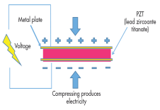
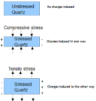
Above figure shows the direct piezoelectric effect
Inverse Piezoelectric Effect
We can reverse the same effect. Inverse piezoelectric effect – when electric field is applied to a crystal it align all dipoles present in the material in order. This realignment results in deformation of crystal i.e. converting electrical energy into kinetic or mechanical energy. Reversal of the piezoelectric effect is called the inverse piezoelectric effect.
Using the inverse piezoelectric effect we can develop devices that produce acoustic sound waves. Even medical ultrasound and sonar transducers use inverse piezoelectric effect.
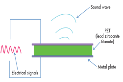
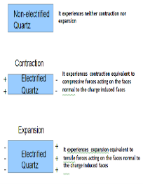
Above figure shows the inverse piezoelectric effect
Examples of Piezoelectric Materials
All piezoelectric materials are non-conductive in order for the piezoelectric effect to occur and work. Quartz is natural and first Piezoelectric Material whereas Lead Zirconate Titanate, Barium Titanate, and Lithium Niobate are man-made Piezoelectric Materials.
Principle:
This is based on the Inverse piezoelectric effect. When a quartz crystal is placed under the effect of an alternating potential difference, vibrations produce in the crystal. If the frequency of electric oscillations coincides with the natural frequency of vibrations of the crystal, the vibrations will be of large amplitude. When the frequency of the electric field matches the ultrasonic frequency range, then the crystal produces ultrasonic waves.
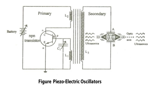
Electric circuit :
Construction:
It is common base NPN oscillator circuit.
Coils L1 and L2 are primary coils of the transformer.
Coil L2 is connected to the collector and L1 connected to the base.
The coil L1 and variable capacitor C1 form the tank circuit of the oscillator.
Quartz crystal is placed between the metal plates A and B so as to form a parallel plate capacitor.
Quartz Crystal is connected to the secondary coil L3 of the transformer through which output or ultrasonic wave is obtained.
The frequency of the oscillations can be changed by changing the value of capacitance.
Working:
As soon as the circuit is closed, the current starts flow through the circuit and charges the capacitor. After the charging is completed the capacitor starts discharging through the inductor L1, this energy is stored in the form of electric field in capacitor C1 and in the form of magnetic field in inductor L1.
Due to this high frequency electric oscillations are produced in the tank circuit. Transistor is also produces electric oscillations. This energy or oscillations is provided to the secondary coil which is again fed to the quartz crystal. Thus oscillating electric field is converted to mechanical vibration of crystal.
When the frequency of electric oscillations is equal to that of natural frequency of the crystal, resonance is achieved and the sound waves of maximum amplitude are produced. Thus by using inverse piezoelectric effect high frequency ultrasonic waves are produced.
Condition for Resonance:
Frequency of the oscillator circuit = Frequency of the vibrating crystal

Where,
L1 is inductance of the circuit
C1 is capacitance of the circuit
t = Thickness of crystal slab
Y = Young's Modulus of material
ρ = Density of material
k = 1, 2, 3 ... (Integer Multiple)
Advantages:
- High frequency Ultrasonic waves can be produced.
- This method is more effective than the Magnetostriction oscillator.
- The output power is very high
- We are able to get a stable and constant frequency of ultrasonic waves.
- It is not affected by temperature humidity
Disadvantages:
- Quartz crystal is very costly.
- Cutting and shaping the crystal is difficult.
Used in Medical applications
- Ultrasonic waves are used to treat the patients having stone in kidney. These high frequency and lower wavelength wave used to break kidney stones into tiny pieces which can be easily flushed out through urine.
- Ultrasonic waves are used in echocardiography.it is used to capture the images of the heart and its features and detect the problems associated with the heart.
- Ultrasonic waves are used in Ultrasound scans/Ultrasonography. It is very commonly used to capture images of internal body organs such as liver, kidney and uterus. It helps to diagnose and helps in treatment problems of the patient. In this method, ultrasound waves are made to travel through the body to the organ. They get reflected from the organ which is to be diagnosed and then these waves converted to electrical signals which can be monitored on a screen.
- Ultrasonography is used to observe the growth of the fetus inside the uterus.
- Ultrasonic waves are used to treat the patients having stone in kidney. These high frequency waves used to break kidney stones into tiny pieces which can be easily flushed out through urine.
Used in Industrial Applications
- Ultrasound is used to clean internal parts of machine Because of the high frequency of the waves, the dust particles just fall out.
- It is used to detect defects, flaws, cracks in machine parts, bridges, building etc. the presence. The ultrasound waves are reflected back from the cracks indicating of a defect.
Used in SONAR (Sound Navigation and Ranging)
- SONAR is a device that uses ultrasonic waves to measure distances which are practically impossible to measure - depth of ocean, distance and direction of underwater objects.
- SONAR comprises of a ultrasound transmitter and detector fitted in a ship. Transmitter transmits ultrasonic wave which travel to the bottom of the ocean and come back and detected.
Used in Food Processing
- Recent years, Ultrasonic waves are also used in food processing.
Definitions:
A dielectric is an electrical insulator that can be polarized by an applied electric field. Or
A dielectric is non-conducting material which stores electrical charges.
In other words, A material that does not conduct electricity but on applying electric field, induced charges produced on its faces. Such an insulator is called Dielectric.
Difference between Dielectric and Insulators
Dielectrics are often confused with insulators. Here are some points of differences
- Dielectric is the material which stores the electrical energy in an electric field whereas insulator is that material which blocks the flow of electrons.
- Dielectric material is polarised whereas insulator material doesn’t get polarised.
- Molecules in dielectric are weakly bounded as compared to molecules in insulator.
- Dielectric material has high dielectric constant whereas insulator has low dielectric constant.
- Examples of Dielectric material are dry air, vacuum, Glass, Porcelain, Various Metal Oxides and distilled water. Whereas Examples of insulator are cotton, plastic, rubber etc.
In dielectric material molecules are tightly bounded to the nucleus and not able to move freely as in case of conductor. But when a dielectric material is placed in an electric field, electric charges do not flow through the material as they flow in case of an electrical conductor but only slightly shift from their average equilibrium positions causing dielectric polarization. Because of dielectric polarization, positive charges are displaced in the direction of the field and negative charges shift in the direction opposite to the field. In dielectric molecules are tightly bound to the nucleus and not able to move freely as in case of conductors. The dielectric material is largely used in the manufacturing of capacitor.
Classification of Dielectrics
The response of a dielectric material depends on the nature of its molecules. The molecules of a dielectric is of two types
- Polar molecules
- Non polar molecules
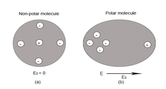
- Polar Molecules: Polar Molecules are those in which centre of gravity of positive and negative charge does not coincide with each other. This is because they all are asymmetric in shape. Examples: H2O, CO2, NO2 etc.
- Non-Polar Molecule: Non-polar molecules are those in which centre of gravity of positive charge and negative charge coincide with each other. The molecule has zero dipole moment as they all are symmetric in shape. Examples: O2, N2, H2 etc.
Response of Dielectric to External Electric Field
In case of Polar Molecules -When the electric field is not present, it causes the electric dipole moment of these molecules in a random direction. This is why the average dipole moment is zero. If the external electric field is present, the molecules align themselves in the direction electric field and resulted in having dipole moment.
In case of Non Polar Molecules – As we know nonpolar molecule has zero dipole moment. In spite of zero dipole, when a dielectric nonpolar material is placed in an electric field. The positive and the negative charges in a nonpolar molecule experience forces in opposite directions. This force causes the separation between the charges and hence nonpolar molecule experiences induced dipole moment.
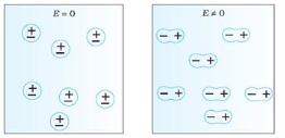
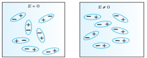
Figure a (left) Non Polar Molecule Figure b (right) Polar Molecule
Dielectric constant it is a quantity measuring the ability of a substance to store electrical energy in an electric field.
Or
The ratio of the permittivity of the substance to the permittivity of the free space
Dielectric constant is also called Relative Permittivity Dielectric Constant is expressed by Greek letter kappa ‘κ’. It is dimensionless quantity.
It is mathematically expressed as:
κ = 
Where,
- κ is the dielectric constant
- 𝜺 is the permittivity of the substance
- 𝜺0 is the permittivity of the free space
Dielectric constant in terms of capacitance
Dielectric constant is equal to the ratio of the capacitance of a capacitor filled with the given material to the capacitance of an identical capacitor in a vacuum without the dielectric material.
If C is the value of the capacitance of a capacitor filled with a given dielectric and C0 is the capacitance of an identical capacitor in a vacuum, the dielectric constant κ, is simply expressed as
κ = 
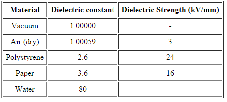
It is defined as the maximum electric field which the material can sustain without breaking down.
When a high electric field is applied to the dielectric, the outer electrons get detached from their parent atoms. The dielectric then behaves as a conductor. In other words every dielectric starts conducting when if an external field is applied to it. This value of electric field depends on the nature of material of dielectric and is called dielectric strength.
List of value of dielctric constant and dielectric strength of some material
Electric displacement, also known as dielectric displacement and usually denoted by D, is a vector field in a non-conducting medium, a dielectric.
In a dielectric material, the presence of an electric field E causes the bound positive and negative charges in the material to slightly separate, inducing a local electric dipole moment. The electric displacement field "D" is defined as
D= 𝜺0E+P
D =
Electric displacement
E = External electric field in which the dielectric is placed
𝜺0 = the permittivity of the free space
P = Polarization Density
In S.I. System, Unit of Electric displacement is C/m2.
In previous section we have seen about the dielectric material’s behaviour and we have seen that when the dielectric material is placed in an electric field, then the molecule of polar and non-polar dielectric gains the dipole moment. Then the dielectric is said to be polarised.
Definition: The diploe moment per unit volume of dielectric material is called the electric polarization of dielectric. It is represented by vector P.
In S.I. System, unit of polarization is C/m2.
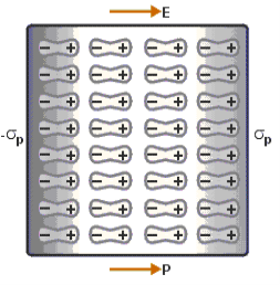
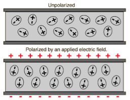
Above figure explains the polarisation of dielectric molecules when the electric field is applied.
There are three types of dielectric polarization
- Electronic Polarization
- Ionic Polarization
- Orientational Polarization
Electronic polarization refers to the separation of centre of positive charge and centre of negative charge in a material.This separation is caused by high electric field.
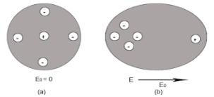
Figure (a) shows thecharge distribution of an atom in absence of electric field while figure (b) show the charge distribution in presence of external electrical field.
Let us consider a single atom of atomic number Z. +e coulomb is the charge of each proton in the nucleus and -e coulomb is the charge of each electron surrounds the nucleus. All electrons in the atom form a spherical cloud of negative charge surrounds the positively charged nucleus. The charge of nucleus is +Ze coulombs and charge of the negative cloud of electrons is -Ze coulombs.
Let us also assume that the negative charge of the electrons cloud is homogeneously distributed on a sphere of radius R. In the absence of external electric field, the center of this sphere and center of nucleus of the atom coincide.
When an external electric field E is applied to the atom. Because of this external electric field the nucleus of the atom is shifted towards negative intensity of the field and the electron cloud is shifted towards the positive intensity of the field.
As due to influence of external electric field the center of nucleus and center of electrons cloud are separated, there will be an attractive force between them according to Coulomb’s law.
Let us suppose x is distance of separation between positive charge nucleus and electron cloud.
Also Nucleus is considered as point charge. Hence, the electrostatic force acting on the nucleus =+EZe …….(1)
As we know nucleus has been shifted from the center of electrons cloud by a distance x.
By using Gauss’s theorem
The force is only due to electron cloud acting upon nucleus would only be due to the portion of the cloud enclosed by the sphere of radius x. Portion outside the sphere of radius x does not apply any force on the nucleus.
Volume of the sphere of radius x = (4/3)πx3 and
Volume of the sphere of radius R = (4/3)πR3
Now total negative charge of the electron cloud is -Ze …..(2)
Hence, the quantity of negative charge enclosed by the sphere of radius x is,
[-Ze/(4/3)πR3] * (4/3)πx3 = -Ze (x3/ R3) ……..(3)
According to coulomb’s law = q1q2 /4 πR2
Here it becomes charge on electrons q1=-Ze (x3/ R3)
Charge on nucleus q2= Ze
So coulomb’s force = {-Ze (x3/ R3) * Ze}/4πƐox2 = Z2e2x/4πƐo R3 ……(4)
Note- magnitude is taken into account. Neglect negative sign.
i.e. At equilibrium Electrostatic force = Coulomb force .
EZe = Z2e2x/4πƐoR3 ……..(5)
Upon simplify
x = {4πƐoR3/Ze} E
Now dipole moment = either charge * separation between charges i.e. x
= Ze *{4πƐoR3/Ze} E
= 4πƐoR3E
Polarization is number of dipole moment per unit volume. Let us suppose N is the number of dipoles per unit volume so
Pe=4πƐoR3EN
So it is clear that polarization depends upon radius of atom or volume of atom and number of atoms present per unit volume.
Ionic polarization occurred only in that dielectric material in which atoms contain ionic bonds. When such a material is placed in an external electric field the separation between positive charge and negative charge is separated through larger distance as compared to original length.
NaCl and KCl molecule shows ionic polarization occurs. In this polarization the net electric field is zero.
Sodium chloride (NaCl) molecule is formed by ionic bond between sodium and chlorine atoms. Due to electrostatic force between positive sodium and negative chlorine ions, they bound together and form sodium chloride molecule. Because of the presence of inter nucleus distance in the sodium chloride molecule, one might think that an ionic crystal would possess polarization even in the absence external electric filed. Since each pair constitute an electric dipole. But this is not so due to lattice symmetry these dipoles cancel each other’s effect.
Figure of NaCl crystal
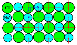
As NaCl have only two atoms or ions there must be a single dipole moment pointing from negative to positive ion in each molecule. But there exists other ionic compounds having more than two atoms.
Number of dipole moments is directly proportional to the number of bonds in a molecule. But all the dipole moments are directed from relatively negative ion to positive ion. The resultant dipole moment of a single molecule would be the vector sum of individual dipole moments of the molecule.
In absence of electric field E, the distance between the ions is d but in presence of electric field, distances between the ions increases.
Figure of NaCl in the presence of electric field
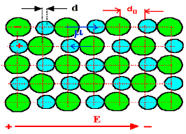
In the presence of electric field we have certain amount of dipole moment.
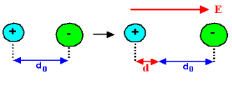
Hence force F1 due to electric field is
F1=qE ……(1)
Where q is the net charge on ion.
F2 restoring force due to binding force between ions
F2=kd …..(2)
Where k is spring constant. Here we are considering bond as spring.
k may also expressed in terms of other constant which is related to the shape of interatomic potential as young’s modulus or modulus of rigidity as
k=Ydo …..(3)
At Equilibrium F1 = F2 at equilibrium distance d
QE = kd
QE = Ydod using (3)
d =  qE/Ydo
Now dipole moment p= qd = q2E/Ydo …..(4)
And polarization Pi = Nq2E / Ydo ……(5)
This is called ionic polarization. This can also be expressed as
Pi =NαiE
Where αi is constant of proportionality known as ionic polarizability constant. This polarization is independent of temperature.
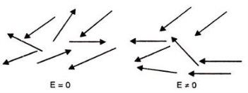
Polar dielectric exhibit orientational polarization. In the absence of electric field, the orientation of the molecule are random and hence the net dipole moment is zero when external force is applied the dipole tried to align themselves along the direction of the applied field. This type of polarization is known as orientational polarization.
Ionic polarization: Orientational polarization: This occurs due to the permanent dipole moment in a material. It occurs in elements such as HCl and H2O.
Potential energy U of the dipole moment making an angle θ with the electric field. Where p0 is the dipole moment.
U=−p0⋅E=−p0Ecosθ
According to statistical mechanics, the number of dipoles or molecules making an angle with the electric field is proportional to
e−U/kT
Letting n(θ) be the number of molecules per unit solid angle at θ, we have
n(θ)=n0e+p0Ecosθ/kT
For normal temperatures and fields, the exponent is small, so we can approximate by expanding the exponential:
n(θ)= n0 (1+p0EcosθkT)
To find n0 , we integrate over all angles and the result is equal to N.
Where N is the total number of molecules per unit volume. The average value of cosθ over all angles is zero, so the integral is just n0 times the total solid angle 4π. We get
n0=N4π or N= n0 /4π
There exits molecules along the field (cosθ=1) than against the field (cosθ=−1). So in any small volume containing many molecules there will be a net dipole moment per unit volume.
As dipole moment is present so polarization Pd is given
Pd =∑unitvolumep0cosθi
Evaluate Total Polarization over solid angle 2πsinθdθ. We have to integrate it
Pd = 0∫π n(θ)p0cosθ2πsinθdθ
Substitute the value of n(θ)
Pd = −N/2 −1∫1 {1+(p0E/kT)cosθ)p0cosθd(cosθ)
By integrating we get,
Pd =Np02E/ 3kT
The polarization is proportional to the field E and depends inversely on the temperature, because at higher temperatures there is more randomness by collisions.
This can also be expressed as
Pd =αdE
Where αd is called dipolar or orientation polarizability and it is equal to p02/ 3kT.
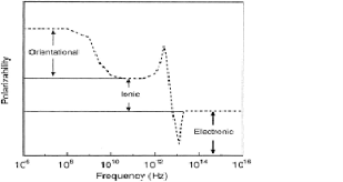
When a dielectric is placed in an electric field the dipoles try to align themselves in the direction of the field. This process requires a finite time that is different for electronic polarization, ionic polarization and dipolar/oreintational polarization.
As long as the frequency is low i.e. less than 106 hertz polarization is independent of frequency and has same value as in static field.
As the frequency increases the molecules dipoles will no longer be able to rotate in phase with the frequency of field and hence will begin to lag behind the field.
As the frequency is still further raised the permanent dipole moment if present in medium will become completely out of phase with the applied field frequency.
Orientation polarization dies off at high frequencies of the applied field this usually happens in the radio frequency range 106-1011 Hz.
At still high frequencies usually happens in the radio frequency range 106-1011 Hz, usually happens in the infra-red frequency range 1011-1014 Hz. The positive and negative ions cannot follow the electric field variations, hence contribution from ionic polarization ceases and only electronic polarization remains at high frequencies.
These effects lead to fall in the permittivity of a dielectric material with increasing frequency and this phenomenon is known as Anomalous Dielectric Dispersion.
