UNIT 4
CRYSTAL STRUCTURE, X-RAYS AND ELECTRODYNAMICS
BASICS OF CRYSTAL STRUCTURE
Crystallography is the experimental science of determining the arrangement of atoms in the crystalline solids. The properties of some materials are directly related to their crystal structures. So first of we will see what crystal structure is. Crystal structure can be defined as
Crystal structure
A crystal is a solid in which the constituent atoms, molecules or ions are packed in a regularly ordered, repeating pattern extending in three dimensions.
Based on the atomic arrangement in a substance, solids can be broadly classified as either crystalline solids or amorphous solids.
Crystalline Solids
In a crystalline solid, all the atoms are arranged in a periodic manner in all three dimensions. Crystalline solids need extreme temperatures to break the intermolecular forces. They have a definite heat of fusion and melting points because of the uniform arrangement of their components. The local environment is also uniform. However, when cut in any direction, the physical properties are different thus known as anisotropic. When rotated around the axis, the structure of crystals remains the same and that is termed as symmetrical arrangement of molecules, atoms or ions. The refractive index, mechanical strength, thermal conductivity and electrical conductivity of crystalline solids differ in different directions.
Amorphous solids
In a non-crystalline or amorphous solid the atomic arrangement is random or non-periodic in nature. The word amorphous is derived from the Greek word amorphous which means “shapeless”. This is the shapeless, disordered, and irregular arrangement of the constituent particles of a solid. Their inter-molecular forces are not the same nor are the distances between the particles. When cleaved, amorphous solids results in curved surfaces because of their irregular geometric shapes. Thermal conductivity, mechanical strength, electrical conductivity and refractive index are the same in all directions of amorphous solids. This explains where the name isotropic comes from. The solids do not have a sharp melting points or a definite heat of fusion. A wide range of temperature needs to be applied before they can melt because of the absence of an ordered array of components. Examples of amorphous solids include polymers, rubbers, plastics and glass.
Difference between Crystalline solids and amorphous solids
Crystalline solids | Amorphous solids |
|
|
2. They have long range order of regular pattern of arrangement of constituent particles. | 2. They have short range order of regular pattern of arrangement of constituent particles. |
3. They are true solids. | 3. They are pseudo solids or super cooled |
4. They have sharp melting points. | 4. They do not have sharp melting points. |
5. They are anisotropic in nature. | 5. They are isotropic in nature. |
6. They have definite heat of fusion. | 6. They do not have definite heat of fusion. |
Space Lattice or Crystal Lattice
In a solid crystalline material, the atoms or molecules are arranged regularly and periodically in all three dimensions. The atomic arrangement in a crystal is called crystal structure.
To explain crystal symmetries easily, it is convenient to represent an atom or a group of atoms that repeats in three dimensions in the crystal as a unit. If each such atom or unit of atoms in a crystal is replaced by a point in space, then the resultant points in space are called space lattice.
Each point in a space lattice is called a lattice point. Each atom or unit of atoms is called basis or pattern.
A space lattice or crystal lattice is defined as three dimensional infinite arrays of points in space in which every point has surroundings identical to that of every other point in the array.
Basis and Crystal Structure
The atomic arrangement in a crystal is called crystal structure. The crystal structure is formed by associating every lattice point with an atom or an assembly of atoms or molecules or ions, which are identical in composition, arrangement and orientation, called the basis. i.e. an atom, or a group of atoms or molecules identical in composition is called the basis or the pattern.
The basis provides the number of atoms per lattice point, their types, mutual orientations and distances of separation between the atoms.
If the basis is substituted for the lattice points, then the resulting structure is called crystal structure as shown in Figure.
Lattice + basis = crystal structure.
The basis shown in Figure contains two different atoms. In copper and sodium crystals the basis is single atoms; In NaCl, the basis is diatomic and in CaF2 the basis is triatomic. A lattice is an imaginary assumption while the crystal structure is a real concept.
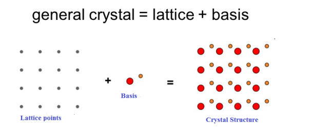
1 Figure: Lattice sites, Basis and crystal structure
Unit Cell and Lattice Parameters
Unit cell is small repeating entity of the atomic structure. It is the basic building block of the crystal structure. It defines the entire crystal structure with the atom positions within.
Unit cells for most of the crystals are parallelepipeds or cubes having three sets of parallel faces. A unit cell is the basic structural unit or building block of the crystal.
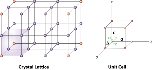
2 Figure: unit cell and unit cell parameter
A unit cell is defined as the smallest parallelepiped volume in the crystal, which on repetition along the crystallographic axes gives the actual crystal structure or the smallest geometric figure, which on repetition in three-dimensional space, gives the actual crystal structure is called a unit cell.
Choice of a unit cell is not unique but it can be constructed in a number of ways as shown in figure. Following figure shows different ways of representing unit cells in a two-dimensional lattice. A unit cell can be represented as ABCD or A′B′C′D′ or A′′B′′C′′D′′, etc.
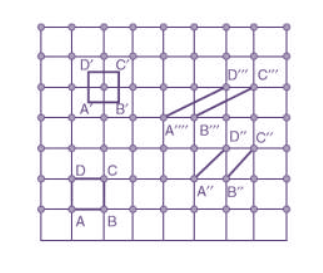
3 Figure: Construction of unit cell in different way
Unit cell parameters or lattice parameters
First we define crystallographic axes. These axes are obtained by the intersection of the three non-coplanar faces of the unit cell. The angles between these faces or crystallographic axes are known as interfacial or interaxial angles. The angles between the axes Y and Z is α, between Z and X is β and between X and Y is γ. The translational vectors or primitives a, b, c of a unit cell along X, Y, Z axes and interaxial angles α, β, γ are called Cell parameters. These cell parameters are shown in (Figure 2). The cell parameters determine the actual size and shape of the unit cell.
Primitive and non-primitive unit cells
The unit cell formed by primitives is called a simple or a primitive unit cell. A primitive unit cell contains only one lattice point. If a unit cell contains more than one lattice point, then it is called a non-primitive unit cell or a multiple unit cell. Most of the unit cells of various crystal lattices contain two or more lattice points and hence it is not necessary that unit cell should be a primitive unit cell.
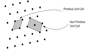
4 Figure: Primitive and non-primitive unit cells
If the surroundings of each lattice point is same or if the atom or all the atoms at lattice points are identical, then such a lattice is called Bravais lattice.
A space lattice represents the geometrical pattern of crystal in which the surroundings of each lattice point is the same. If the surroundings of each lattice point is same or if the atom or all the atoms at lattice points are identical, then such a lattice is called Bravais lattice.
On the other hand, if the atom or the atoms at lattice points are not same, then it is said to be a non-Bravais lattice.
For representing the type of distribution of lattice points in space, seven different co-ordinate systems are required. These co-ordinate systems are called crystal systems.
The crystal systems are named on the basis of geometrical shape and symmetry. The seven crystal systems are:
(1) Cubic
(2) Tetragonal
(3) Orthorhombic
(4) Monoclinic
(5) Triclinic
(6) Trigonal (or Rhombohedral)
(7) Hexagonal.
In 1948, Bravais showed that 14 lattices are sufficient to describe all crystals. These 14 lattices are known as Bravais lattices and are classified into 7 crystal systems based on cell parameters or lattice points present per unit cell.
Bravais lattices are categorized as
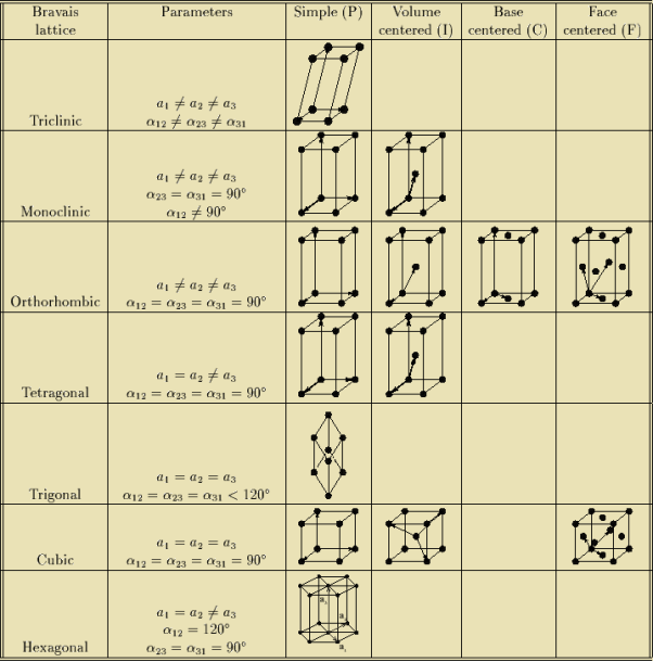
The cubic crystal system is one of the most common (and by far the simplest) class of crystals. As the name itself suggests, all crystal structures of this system have a cube-shaped unit cell with edge length given by the lattice parameter ‘a’.
The three main common representatives are:
- Simple or Primitive Cubic (SC) (also known as primitive cubic)
- Body-centered Cubic (BCC)
- Face-centered Cubic (FCC)
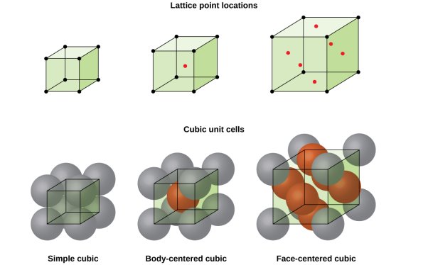
5 Figure: SC, BCC, FCC structure
Simple or Primitive lattice
In simple or primitive lattice, 8 lattice points or 8 atoms are present at the 8 corners of the unit cell, each contributing 1/8thto the unit cell and hence there will be 8 x 1/8 = 1 lattice point per unit cell.
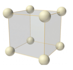
6 Figure: simple or primitive lattice
Body-centered lattice
In body-centered lattice, in addition to the 8 atoms at 8 corners each contributing 1/8thto the unit cell, there will be one complete atom at the center of the unit cell. Therefore number of atoms or lattice points in a body centered unit cell becomes 8 x 1/8 + 1 x 1 = 2.
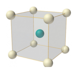
7 Figure: Body-centered lattice
Face-centered lattice (F)
In case of face-centered lattice, in addition to the 8 atoms at 8 corners each contributing 1/8thto the unit cell, six atoms will be present at the center of six faces of the cell each contributing 1/2nd to the unit cell. Therefore number of atoms or lattice points in a face centered unit cell becomes 8 x 1/8 + 6 x 1/2 = 4.
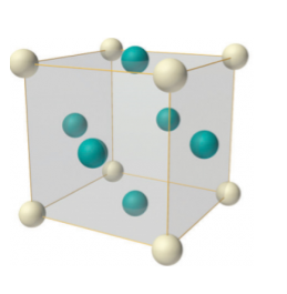
8 Figure: Face-centered lattice (F)
The number of nearest neighbour atoms or ions surrounding an atom or ion is known as coordination number.
It is measure of closeness of packing of atoms in any given structure. It equals the number of nearest neighbour that surrounds each atom.
Simple or Primitive Cubic Crystal
In simple cubic system 6 neighbours atoms at a distance of ‘a’ each from the selected atom as shown in figure. So the coordination number of SC is six.
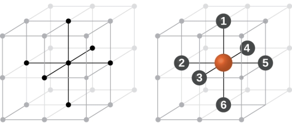
9 Figure: Simple Cubic Crystal
Body Centred Cubic Crystal
In Body Centred Cubic system 8 neighbour atoms are in touch with the selected atom as shown in figure. So the coordination number of BCC is eight.
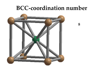
10 Figure: Body Centred Cubic Crystal
Face Centred Cubic Crystal
In Face Centred Cubic system 12 neighbour atoms are in touch with the selected atom as shown in figure. So the coordination number of FCC is twelve.
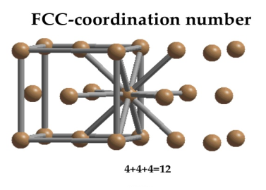
11 Figure: Face Centred Cubic Crystal
Atoms are not hard spheres with distinct boundaries, so their sizes are not determined directly. However, the positions of the atoms in a solid can be determined by x-ray diffraction, and the sizes of the atoms are inferred from those distances.
In this method, the radius of an atom is determined from the unit cell edge length (a), which is determined from the location of the atoms, and the assumption that the atoms touch as shown in below.
Simple or Primitive Cubic Crystal
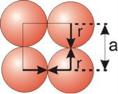
2r = a
Body Centred Cubic Crystal
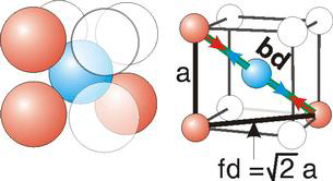
Bd | = | 4r |
|
|
|
|
|
|
Bd2 | = | Fd2 + a2 |
|
|
|
|
|
|
(4r)2 | = | 2a2 + a2 = 3a2 |
Face Centred Cubic Crystal
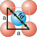
Fd | = | 4r |
|
|
|
|
|
|
Fd2 | = | a2 + a2 |
|
|
|
|
|
|
(4r)2 | = | 2a2 |
Relationship of Atomic Radii and Unit Cell Edge Lengths
Setting the edge length equal to 2r in the sc unit cell, and applying the Pythagorean theorem to the triangles shown in Figures we obtain the relationships between the atomic radius (r) of the atom and the edge length of the unit cell (a) given in Equation
For SC r = a/2
For BCC r = 
For FCC r = 
It is impossible to pack spheres without introducing some void space (space that is not occupied). How well the atoms pack a unit cell depends upon the unit cell type and is given by the packing efficiency of the unit cell. Solids with tightly packed unit cells are denser than those with low packing efficiencies. In this section, we examine the packing efficiencies of the cubic unit cells and show how to determine the density of a solid from its crystal structure.
Density
Density is the mass-to-volume ratio of a substance.
Density d = mass of substance / volume of substance
|
Packing Efficiency
Packing efficiency is the fraction of the unit cell that is occupied by particles. Spheres cannot be packed without creating some void space, but the amount of void space depends upon how well they are packed. Packing efficiency (PE) is that fraction of the unit cell volume that is actually occupied by particles, not void space. Thus, the packing efficiency of a unit cell is
Packing Fraction =  |
|
PE =  |
a = the length of a side of the unit cell, so a3 is the volume of the unit cell.
r = the radius of the atoms that occupy the unit cell, so (4/3)πr3 is the volume of a single atom in the unit cell.
N = the number of atoms in the unit cell, so N(4/3)πr3 is the volume occupied by all of the atoms in the unit cell.
The unit cell size (a) is directly proportional to the atom size (r), so one can be defined in terms of the other.
Consequently, the packing efficiency depends only upon the cell type, not its size. As shown in the next sections, the relationship between a and r depends only upon the unit cell type.
Packing in Simple Cubes
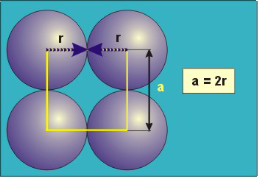
12 Figure
In the simple cubic unit cell, the spheres touch along the cell edge. Consequently, the edge length is two atomic radii
(a = 2r).
The properties of the simple cubic unit cell:
r = 0.5a
N = 1 atom/unit cell
PE =  |
Packing efficiency = 52%
Coordination number = 6
Packing in Body-Centered Cubes
13 Figure
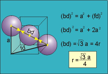
For the body-centered cubic unit cell, the spheres make contact along the body diagonal (bd), which is four atomic radii (each yellow arrow is one atomic radius), i.e., bd = 4r.
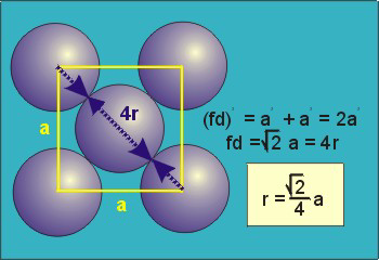
The body diagonal is related to the face diagonal (fd) and the cell edge (a) by the Pythagorean theorem. The relationship between the cell edge and the face diagonal was derived in the discussion of the fcc unit cell. The properties of the body-centered cubic unit cell:
For BCC r = 
r = 0.433 a
N = 2 atoms/unit cell
PE =  |
Packing efficiency = 68%
Coordination number = 8
Packing in Face-Centered Cubes
14 Figure
For FCC r = 
r= 0.354a
N = 4 atoms/unit cell
PE =  |
Packing efficiency = 74%
Coordination number = 12
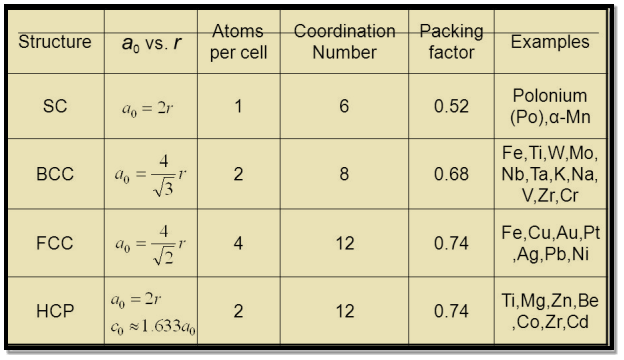
As shown in the previous sections, the packing efficiency of a unit cell depends only on the cell type; it is independent of edge length and atomic radius because both cancel in the calculation. As might be expected, the packing efficiency increases as the number of atoms in the unit cell and the number of atoms that are packed around each atom (coordination number) increases.
Table: Packing Efficiencies and Coordination Numbers of Cubic Lattices
Lattice | Packing | Coordination |
Simple | 52% | 6 |
Body-centered | 68% | 8 |
Face-centered | 74% | 12 |
Table for Sc, Bcc, Fcc, Hcp Lattices
The first important thing to understand is that a cubic crystal is made up a crystal lattice or a space lattice structure. And as we have studied before, a space lattice is made up of a repeating arrangement of unit cells. A unit cell is the most basic structure of a crystalline solid.
Hence if we are able to find the density of a unit cell, it can be said that we have found the density of the cubic crystal itself. With this in mind, let us determine how to arrive at the density of a cubic crystal cell.
Now as we know a unit cell also has a cubic structure. It has one, two or four atoms located at various lattice points. Now with the help of geometry, some basic calculations and certain attributes of this cubic structure we can find the density of a unit cell. Let us start with the basic formula for the density of any solid. This formula is
Density = Mass/ Volume
The density of a Unit Cell will be
D = Mass of Unit Cell / Volume of Unit Cell
Mass of a Unit Cell
Now to calculate the mass of one unit cell we add up the mass of all the atoms contained in that particular cell. The number of atoms will depend on the kind of cell it is. So to obtain the mass of a unit cell we multiply the number of atoms “n” into the mass of each atom ”m”.
Mass of Unit Cell = m × n
But now the question remains, what is the mass of an atom? Well, this can be represented in terms of its Avogadro Number (NA)., i.e. number of units in one mole of any substance and the molar mass of an atom. So the mass of an atom can be calculated as
Mass of an Atom = 
Mass of an Atom = 
So now the formula for Mass of Unit Cell is as follows
Mass of Unit Cell = n × 
Volume of Unit Cell
As we already know, the unit cell is a cubic structure. So the Volume of a cube is the cube of the length of the side, Assume that the length of the side of the cube is “a”.
Volume of Unit Cell = a3
Density of Unit Cell
And now we finally arrive at the actual formula for the density of a unit cell
Density of a Unit Cell = 
Density of a Unit Cell = 
Example: An atomic solid crystallizes in a body center cubic lattice and the inner surface of the atoms at the adjacent corner are separated by 60.3 pm. If the atomic weight of A is 48, Find the density of the solid?
Solution:
According to given condition,
0.13 a = 60.3 ⟹ a = 463.8
So Density = 
= 
= 1.75 g/cc
When dealing with crystalline materials, it often becomes necessary to specify a particular point within a unit cell, a crystallographic direction, or some crystallographic plane of atoms.
Labelling conventions have been established in which three numbers or indices are used to designate point locations, directions, and planes. The basis for determining index values is the unit cell, with a right-handed coordinate system consisting of three (x, y, and z) axes situated at one of the corners and coinciding with the unit cell edges.
For some crystal systems—namely, hexagonal, rhombohedral, monoclinic, and triclinic-the three axes are not mutually perpendicular, as in the familiar Cartesian coordinate scheme. A crystallographic direction is defined as a line between two points, or a vector.
The following steps are utilized in the determination of the three directional indices:
1. A vector of convenient length is positioned such that it passes through the origin of the coordinate system. Any vector may be translated throughout the crystal lattice without alteration, if parallelism is maintained.
2. The length of the vector projection on each of the three axes is determined; these are measured in terms of the unit cell dimensions a, b, and c.
3. These three numbers are multiplied or divided by a common factor to reduce them to the smallest integer values.
4. The three indices, not separated by commas, are enclosed in square brackets, thus: [hkl]. The h, k, and l integers correspond to the reduced projections along the x, y, and z axes, respectively.
Crystal planes are defined as some imaginary planes inside a crystal in which large concentration of atoms are present. Inside the crystal, there exists certain direction along which large concentration of atoms exists. These directions are called crystal directions.
Miller Indices are a method of describing the orientation of a plane or set of planes within a lattice in relation to the unit cell. They were developed by William Hallowes Miller.
Crystal planes and directions can be represented by a set of three small integers called Miller indices [because Miller derived a method of representing crystal planes]. These integers are represented in general as h, k and l. If these integers are enclosed in round brackets as (hkl), then it represents a plane. On the other hand, if they are enclosed in square brackets as [hkl], then it represents crystal direction perpendicular to the above-said plane.
Procedure for drawing the given plane having Miller indices (hkl)
1. A unit cell is drawn with the given lattice parameters. After taking any convenient point as the origin O, the OX, OY and OZ crystallographic axes are to be marked. If lattice parameters are not given, then unit cubic cell of arbitrary lattice constant will be taken.
2. The reciprocals of the Miller indices 1/h, 1/k, 1/l are to be taken. These values provide the intercepts of the given plane on OX, OY and OZ axes, respectively.
3. The intercepts are marked in the unit cell and the plane is drawn.
4. If the intercept is  on any axis, the plane drawn will be parallel to that axis.
Example:
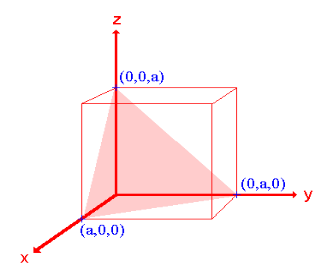
- The (111) surface
Intercepts: a , a , a
Fractional intercepts: 1 , 1 , 1
Miller Indices: (111)
 |
Ii. The (110) surface
Intercepts: a , a , ∞
Fractional intercepts: 1 , 1 , ∞
Miller Indices: (110)
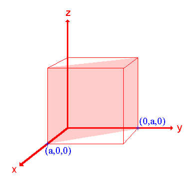 |
|
Iii. The (210) surface
Intercepts: ½a , a , 
Fractional intercepts: ½ , 1 , 
Miller Indices: (210)
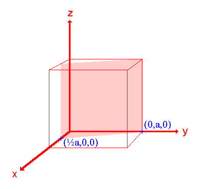 |
|
Table
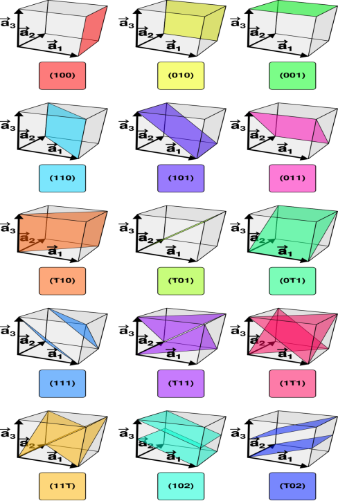
Distance of separation between successive hkl planes
The separation between successive parallel planes in rectangular axes crystal system can be extracted easily.
Consider a plane ABC which belongs to a family of planes. h, k, l are the Miller indices of this plane, which represents the set of planes. The perpendicular ON from the origin O to the plane represents the inter-planar spacing d = ON of this family of planes. Let ON make an angle α’, β’, γ’ with the x, y, z axes respectively.
The intercepts of the plane on the three axes are OA= a/h; OB= a/k; OC=a/l Where ‘a’ is the length of the cube edge. Then from figure, we have
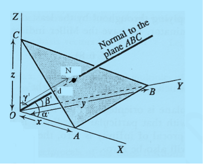
15 Figure
Cos =
=  =
=  =
= 
Cos =
=  =
=  =
= 
Cos =
=  =
=  =
= 
From the figure ON = 
d = 
But, 
Substituting the values of cos’, cos’, cos’ in equation (2), We get,
For the orthogonal coordinates Substituting the values of cos’, cos’, cos’ in equation (2), We get,
(  )2 + (
  )2 +(
)2 +(  )2 = 1
( )2 + (
 )2 +(
)2 +( )2 = 1
( ) (
) ( ) = 1
) = 1
d = 
d = 
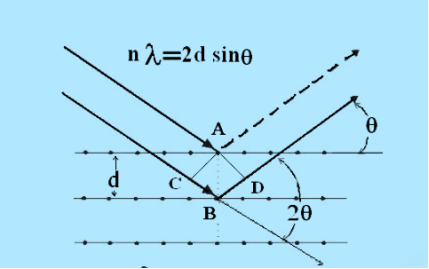
Consider a set of parallel planes called Bragg’s planes. Each atom is acting as a scattering center. The intensity of the reflected beam at certain angles will be maximum when the path difference between two reflected waves from two adjacent planes is an integral multiple of λ.
16 Figure
Let ‘d’ be the distance between two adjacent planes, 'λ’ be the wavelength of the incident x-ray, ‘θ’ be the glancing angle.
The path difference between the rays reflected at A & B is given by
 = CB + BD= d sinθ + d sinθ = 2dsinθ
If the two consecutive planes scatter waves in phase with each other, then the path difference must be an integral multiple of wavelength.
 = nλ
= nλ
For the reflected light intensity to be maximum, the path difference
nλ= 2dsinθ
Where ‘n’ is the order of scattering.
This is called Bragg’s law
Therefore, Bragg’s law states that X-rays diffracted from different parallel planes of a crystal interfere constructively when the path difference is integral multiples of wavelength of X-rays.
From Bragg’s law nλ = 2d sin θ, since maximum possible value for sin θ is 1,
nλ/2d ≤ 1 or λ ≤ 2d.
This sets the limitation on the wavelength, i.e. in order to get the diffraction pattern by a crystal, the wavelength of X-rays should not exceed twice the inter-planar spacing.
Importance of Bragg’s law:
1. Bragg’s law is the essential condition to be satisfied by crystal planes in order to get diffraction pattern from a crystal.
2. It is used to calculate inter-planar spacing. Knowing the values of inter-planar spacing, lattice parameters can be determined.
The visible light rays when pass through a sharp edge of an object can form some bright regions inside the geometrical shadow of the object. This is due to the bending nature of light, called diffraction. Diffraction can occur whenever Bragg’s law is satisfied.
LAUE METHOD
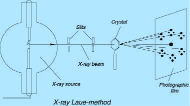
The Laue method was the first diffraction method ever used. This method is used to study the orientation of crystal and to verify crystal symmetry. A beam of white radiation, the continuous spectrum from an x-ray tube, is allowed to fall on a fixed single crystal. The Bragg angle θ is therefore fixed for every set of planes in the crystal, and each set picks out and diffracts that particular wavelength which satisfies the Bragg law for the particular values of d and involved. Each diffracted beam thus has a different wavelength.
17 Figure
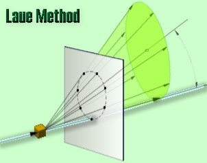
There are two variations of the Laue method, depending on the relative positions of source, crystal, and film. In each, the film is flat and placed perpendicular to the incident beam. The film in the transmission Laue method (the original Laue method) is placed behind the crystal so as to record the beams diffracted in the forward direction. This method is so called because the diffracted beams are partially transmitted through the crystal. These curves are generally ellipses or hyperbolas for transmission patterns.
In the transmission Laue method, the film is placed behind the crystal to record beams which are transmitted through the crystal.
One side of the cone of Laue reflections is defined by the transmitted beam. The film intersects the cone, with the diffraction spots generally lying on an ellipse
18 Figure
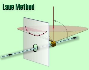
In the back-reflection Laue method the film is placed between the crystal and the x-ray source, the incident beam passing through a hole in the film, and the beams diffracted in a backward direction are recorded. In either method, the diffracted beams form an array of spots on the film as shown in Figure. This array of spots is commonly called a pattern, more specifically, Laue pattern, but the term is not used in any strict sense and does not imply any periodic arrangement of the spots. On the contrary, the spots are seen to lie on certain curves, as shown in figure for transmitted pattern. These curves are generally hyperbolas for back-reflection patterns.
In the back-reflection method, the film is placed between the x-ray source and the crystal. The beams which are diffracted in a backward direction are recorded.
One side of the cone of Laue reflections is defined by the transmitted beam. The film intersects the cone, with the diffraction spots generally lying on an hyperbola.
19 Figure
The spots lying on any one curve are reflections from planes belonging to one zone. This is due to the fact that the Laue reflections from planes of a zone all lie on the surface of an imaginary cone whose axis is the zone axis. The positions of the spots on the film, for both the transmission and the back-reflection method, depend on the orientation of the crystal relative to the incident beam, and the spots themselves become distorted and smeared out if the crystal has been bent or twisted in any way.
The facts account for the two main uses of the Laue methods include: the determination of crystal orientation and the assessment of crystal perfection.
Laue method is useful to decide the crystal symmetry and orientation of the internal arrangement of atoms/molecules in the crystal.
The atomic arrangement in a crystal can be analysed by studying the positions and intensities of spots in Laue pattern.
As several wavelengths of X-rays can reflect in different orders from the same set of planes with the different order reflections superimposed on the same spot in the film, the intensity of the spots and hence the cell parameters of a crystal cannot be determined using Laue method.
For transmission Laue method, the crystal should be thin.
Laue method can be used to study imperfections or strains in the crystal. The presence of above defects forms streaks instead of spots in the Laue photograph.
Origin of Continuous X-ray Spectra
The line spectrum of an element originate when electrons are expelled from inner shells of its atoms and the electrons from higher levels fall into these vacancies in the inner shells. Each such transition causes energy loss equal to the energy difference of shells which appears as an X-ray photon.
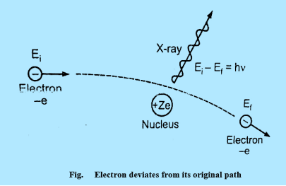
Continuous X-ray spectrum is the result of inverse photoelectric effect. Continuous X-ray is produced by the phenomenon of “Bremsstrahlung” which is German word meaning “breaking radiation”. Electrons are emitted from the cathode in the X-rays are accelerated towards the target or plate and strike it, penetrate deep into the interior of its atoms and are attracted by the nuclei due to strong electrostatic interaction. The electron therefore deviates from its original path as shown in figure
20 Figure
The deviation of the electron from its straight line path is equivalent to its collision with the nucleus. The electrons are loss more of its kinetic energy due to the collision.
This energy appears as an X-ray photon.
Ei & Ef are initial kinetic energy and the final kinetic respectively.
Ei - Ef h
The electron may suffer several collisions with various nuclei before coming to rest and each collision is accompanied by the emission of an X-ray photon. Hence, a number of photons of different frequencies are emitted. As there are large numbers of electrons in the beam and each electron collision in a different way, we get photons of almost all frequencies or wavelengths, thus producing a continuous X-ray spectrum.
According to classical theory, the continuous X-ray spectrum should consists of all frequencies between zero and infinity. But according to quantum theory, there is a minimum wavelength up to which is the continuous X-ray spectrum extends. To find the value of min, let the velocity of the incident electron decrease from vi to vf due to the interaction with the nucleus. Then the frequency of X-ray photon is given by
h =  mvi2 -
  mvf2 …………….(1)
When electron is brought to rest by electrostatic interaction, vf =0 and photon has maximum frequency or minimum wavelength.
hmax =  mvi2 …………….(2)
If V is potential difference between cathode and target or plate the
 mvi2 = eV …………….(3)
From (2) and (3), we have
hmax = eV …………….(4)
λmin = 
From (4) we have
λmin = 
λmin =  Å …………….(5)
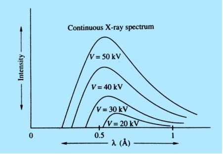
The lowest wavelength limit of continuous spectra is inversely proportional to the accelerating potential of X-ray tube λmin 

Continuous spectrum of X-rays consists of all radiation of all possible X-ray wavelengths within a certain range starting from min (i.e. the wavelength corresponding to minimum energy) onwards. The continuous spectrum is also known as general spectrum or white spectrum.
The plot of relative intensity of X-ray spectra versus wavelength in various potential differences applied to an X-ray tube between the cathode and target or plate is shown in figure. It is clear that by varying the X-ray tube accelerating potential, the min shifts toward left i.e. the X-ray achieve more energy; the intensity of X-rays also increases with voltage.
21 Figure
This law advanced chemistry by immediately sorting the elements of the periodic table in a more logical order. Moseley could predict the existence of several then-unknown elements. A law that relates the frequency of the spectral lines of the characteristic X-radiation of a chemical element to its atomic number. This law was experimentally established by H. Moseley in 1913.
According to Moseley’s law, the square root of the frequency v of a spectral line of the characteristic radiation of an element is a linear function of its atomic number Z:

Where R is the Rydberg constant
Sn is the screening constant
n is the principal quantum number.
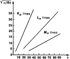
On a Mosley plot the dependence of  on Z is a series of lines (such as the Kα lines, Lα lines, and Mα lines, which correspond to the values n = 1,2, and 3).
Mosley’s law was incontrovertible proof of the correctness of the arrangement of the elements in D. I. Mendeleev’s periodic system of the elements and the law helped to clarify the physical significance of Z.
According to Moseley’s law, the characteristic X-ray spectra do not display the periodic regularities that are inherent in optical spectra. This indicates that the inner electron shells of the atoms of all elements, which are manifested in the characteristic X-ray spectra, have an analogous structure.
22 Figure
Subsequent experiments revealed some deviations from a linear
Subsequent experiments revealed some deviations from a linear Moseley plot for the Kα lines, Lα lines, and Mα lines of characteristic X-radiation. The atomic number of the element Z is plotted along the axis of abscissas and the quantity  (where c is the velocity of light) is plotted along the axis of ordinates.
Dependence for the transition groups of elements the deviations being due to the change in the order in which the outer electron shells are filled and also for heavy atoms, in which the deviations result from relativistic effects (and may provisionally be explained by the fact that the velocities of the inner electrons are comparable with the velocity of light).
The position of the spectral lines on a Moseley plot may vary somewhat, depending on a number of factors, such as the number of nucleons in the nucleus (isotope shift) and the state of the outer electron shells (chemical shift). The study of these shifts makes it possible to obtain detailed information about the atom.
Importance of Moseley's law:
- Using this law Moseley arranged K and Ar, Ni and CO in a proper way in Mendeleev's periodic table.
- This law was held to the discovery of many new elements like Tc (43), Pr (61), Rh (45).
- The atomic number of rare earth have been determined by this law.
Maxwell equations are of fundamental importance since they describe the whole of classical electromagnetic phenomena.
From a classical perspective, light can be described as waves of electromagnetic radiation. As such, Maxwell equations are very useful to illustrate a number of the characteristics of light including polarization.
We are just to stating these equations without derivation. Since our goal is simply to apply them, the usual approach will be followed.
Maxwell’s four equations are given by
∇·E = ρ/ε0 (1)
∇×E = −∂B/∂t (2)
∇×H = J + ∂D/∂t (3)
∇·B = 0 (4)
These equations illustrate the unique coexistence in nature of the electric field and the magnetic field. The first two equations give the value of the given flux through a closed surface, and the second two equations give the value of a line integral around a loop. In this notation,
∇=(∂/∂x, ∂/∂y, ∂/∂z)
E is the electric vector
B is the magnetic induction
ρ is the electric charge density
j is the electric current density
ε0 is the permittivity of free space
c is the speed of light.
In addition to Maxwell equations, the following identities are useful:
J = σE (5)
D = εE (6)
B = μH (7)
Here,
D is the electric displacement
H is the magnetic vector
σ is the specific conductivity
ε is the dielectric constant (or permittivity)
μ is the magnetic permeability
In the Gaussian systems of units, Maxwell equations are given in the form of
∇·B=0 (8)
∇·E=4πρ (9)
∇×H=(1/c)(∂D/∂t+4πj) (10)
∇×E=−(1/c)(∂B/∂t) (11)
Maxwell’s four equations are given by
∇·E = ρ/ε0 (1)
∇×E = −∂B/∂t (2)
∇×H = J + ∂D/∂t (3)
∇·B = 0 (4)
For free space or non-conducting medium. We know that non conducting medium means no current so conductivity is zero i.e. σ=0
So current density J=σE will also become zero as σ=0 Also free space means no charges which leads to ρ=0. These points mentioned below.
(a) No condition current i.e σ=0, thus J=0 ( J=σE)
(b) No charges (i.e ρ=0)
For the case of no charges or currents, that is, j = 0 and ρ = 0, and a homogeneous medium. Using these the Maxwell equation can rewritten as
∇.D=0 or ∇.E=0 as ρ=0 (12)
∇ x E= -dB/dt or ∇ x E= -μ dH/dt because B = μH (13)
∇ x H=d D/dt or ∇ x H = ε dE/dt (J=0) and D = εE (14)
∇.B=0 (15)
Now taking curl of second Maxwell’s equation (13) ,we get
∇ x(∇ x E)=- μ d/dt (∇ x H)
Applying standard vector identity, that is [∇ *(∇*E)=∇(∇.E)-∇2E] on left hand side of above equation, we get
∇ (∇ .E)-∇2E= -μ d/dt (∇ x H) (16)
Substituting equations (13) and (14) in equations (16) ,we get
-∇2E= – με d/dt (dE/dt)
Or ∇2E=με d 2 E/dT2 (17)
Equation (17) is the required wave equation in terms of electric field intensity, E for free space . This is the law that E must obey.
Wave Equation In Terms Of Magnetic Field Intensity, H
Take curl of fourth Maxwell’s equation(14) ,we get
∇x(∇xH)=ε d/dt(∇xE)
Applying standard vector identity that is
[∇*(∇*H)=∇ (∇.H)-∇2H]
On left side of above equation , we get
∇(∇.H)-∇2H= ε d/dt(∇xE) (18)
Substituting equations (14) and (13) in equation(18) ,we get
-∇2H= – μεd/dt(dH/dt)
Or
∇2H=με d2H/dt2 (19)
Equations (19) is the required wave equation in terms of magnetic field intensity, H and this is the law that H must obey
For vacuum μ=μ0 and ε=ε0, equations (17) and (19) will become
∇2 E=μ0ε0 d2E/dt2 (20)
And ∇2H= μ0ε0 d2H/dt2 (21)
This leads to an expression for the velocity of propagation
From equation both equations (20) and (21) have the form of the general wave equation for a wave

(x,t) traveling in the x direction with speed v. Equating the speed with the coefficients, we derive the speed of electric and magnetic waves, which is a constant that we symbolize with “c”
It is useful to note that in vacuum
c2=1/ε0μ0
Where μ0 is the permeability of free space
