UNIT 5
MAGNETIC, SUPERCONDUCTING AND SEMICONDUCTING MATERIALS
The magnetic effects in magnetic materials are due to atomic magnetic dipoles in the materials. These dipoles result from effective current loops of electrons in atomic orbits, from effects of electron spin & from the magnetic moments of atomic nuclei.
The electric currents in an atom are caused by orbital and spin motions of electrons and those of its nucleus. Since all these motions of charged particles form closed electric currents, they are equivalent to “magnetic dipoles”. When such dipoles are subjected to an external electric field, they experience a torque which tends to align their magnetic moments in the direction of the externally applied field.
Some Important Definitions
Magnetic dipole
Each tiny dimension of a magnetic material (or) atoms in magnetic materials is called magnetic dipole. This magnetic dipole produces magnetic moment depending on the alignment with respect to the applied magnetic field.
Magnetic flux (Ф)
It is defined as the amount of magnetic lines of forces passing perpendicularly through unit area of a given material. It is denoted by ‘Ф’
Ф=AB
Where A= Area of cross section of the material in m2
B = magnetic Induction in Wb/ m2
Units: Weber (Wb)
Intensity of Magnetization (M)
When a material is magnetized, it develops a net magnetic moment. The magnetic moment per unit volume is called Intensity of magnetization.
Magnetization (M) = 
Units: Amp/m
Magnetic Induction (B)
Magnetic induction at a point is defined as the force experienced by a unit North Pole Placed at that point. It is denoted by ‘B’i.e.
B =
Unit is weber / m2
Magnetizing field strength (H)
When a medium is exposed to a magnetic field of intensity ‘H’, it causes an induction ‘B’ in the medium.i.e. B H
B = μH
Where μ = absolute permeability of the medium. If the medium is air or vacuum B=μ0H
μ0=permeability of free space i.e. air or vacuum
μ0=4𝜋×10-7 H/m
Units for H: Amp /m
Permeability (μ)
It indicates with which the material allows magnetic lines of force to pass through it.
Or
It is the ability of the medium to pass magnetic lines of forces through it.
There are three Permeabilities i.e. μ1,μ0, μr
μ = μ0μr
Where μ = Absolute permeability of the medium
μ0 = Permeability of free space i.e. air or vacuum
μr = Relative permeability of the medium
Magnetic moment
Magnetic moment μm = (current) × (area of circulating orbit)
μm = (I) × (𝜋r2)
Units: Amp-m2
When the magnetic dipoles (atoms consisting of charged particles like protons & neutrons) undergo orbital motion (or) spin motion produces a magnetic moment. Since motion of charged particles is considered as closed electric current loops which in turn produces a magnetic moment.
Magnetic susceptibility (χ)
If H is the applied magnetizing field intensity and M is the amount of magnetization of the material,
Then χ = 
χ = 0 in vacuum
χ = +ve for paramagnetic and Ferro magnetic materials
χ = -ve for diamagnetic materials
Units: It has no units.
Classification of Magnetic Materials
Magnetic materials are classified as follows:
- Diamagnetic
- Paramagnetic
- Ferro magnetic
- Anti-Ferro magnetic
- Ferric magnetic or ferrites
- Garnets
Diamagnetic
The orbital motion of electrons around the nucleus produces a magnetic field perpendicular to the plane of the orbit. Thus each electron orbit has finite orbital magnetic dipole moment. Since the orbital planes are oriented in random manner, the vector sum of magnetic moments is zero and there is no resultant magnetic moment for each atom.
In the presence of an external magnetic field, some electrons are speeded up and some are slowed down. The electrons whose moments were anti-parallel are speeded up according to Lenz’s law and this produces an induced magnetic moment in a direction opposite to the field. The induced moment disappears as soon as the external field is removed.
When placed in a non-uniform magnetic field, the interaction between induced magnetic moment and the external field creates a force which tends to move the material from stronger part to weaker part of the external field. It means that diamagnetic material is repelled by the field.
This action is called diamagnetic action and such materials are known as diamagnetic materials. Examples: Bismuth, Copper and Water etc.
The properties of diamagnetic materials are
- Magnetic susceptibility is negative.
- Relative permeability is slightly less than unity.
- The magnetic field lines are repelled or expelled by diamagnetic materials when placed in a magnetic field.
- Susceptibility is nearly temperature independent.
- Examples: Cu, Au, Zn, H20, Bi etc. organic materials
Paramagnetic materials
In some magnetic materials, each atom or molecule has net magnetic dipole moment which is the vector sum of orbital and spin magnetic moments of electrons. Due to the random orientation of these magnetic moments, the net magnetic moment of the materials is zero.
In the presence of an external magnetic field, the torque acting on the atomic dipoles will align them in the field direction. As a result, there is net magnetic dipole moment induced in the direction of the applied field. The induced dipole moment is present as long as the external field exists.
The properties of paramagnetic materials are:
- Magnetic susceptibility is positive and small.
- Relative permeability is greater than unity.
- The magnetic field lines are attracted into the paramagnetic materials when placed in a magnetic field.
- Susceptibility is inversely proportional to temperature.
Ferromagnetic materials
An atom or a molecule in a ferromagnetic material possesses net magnetic dipole moment as in a paramagnetic material. A ferromagnetic material is made up of smaller regions, called ferromagnetic domain (Figure 3.27). Within each domain, the magnetic moments are spontaneously aligned in a direction. This alignment is caused by strong interaction arising from electron spin which depends on the inter-atomic distance. Each domain has net magnetisation in a direction. However the direction of magnetisation varies from domain to domain and thus net magnetisation of the specimen is zero.
In the presence of external magnetic field, two processes take place
1. the domains having magnetic moments parallel to the field grow in size
2. the other domains (not parallel to field) are rotated so that they are aligned with the field.
As a result of these mechanisms, there is a strong net magnetisation of the material in the direction of the applied field
When placed in a non-uniform magnetic field, the ferromagnetic materials will have a strong tendency to move from weaker to stronger part of the field. Materials which exhibit strong magnetism in the direction of applied field are called ferromagnetic materials. Examples: Iron, Nickel and Cobalt.
The properties of ferromagnetic materials are:
- Magnetic susceptibility is positive and large.
- Relative permeability is large.
- The magnetic field lines are strongly attracted into the ferromagnetic materials when placed in a magnetic field.
- Susceptibility is inversely proportional to temperature.
Antiferromagnetism
In the periodic table the only element exhibiting antiferromagnetism at room temperature is chromium. Antiferromagnetic materials are very similar to ferromagnetic materials but the exchange interaction between neighbouring atoms leads to the anti-parallel alignment of the atomic magnetic moments. Therefore, the magnetic field cancels out and the material appears to behave in the same way as a paramagnetic material. Like ferromagnetic materials these materials become paramagnetic above a transition temperature, known as the Neel temperature, TN. (Cr: TN=37ºC).
The properties of antiferromagnetic materials are:
- They have permanent magnetic dipoles
- They do not possess permanent magnetic dipole moment. Since in the absence of field they have no spontaneous magnetization due to anti parallel spin
- The relative permeability μr>1
- Susceptibility χ is small but negative
- 𝜒depends on temperature
Ferrimagnetism
Ferrimagnetism is only observed in compounds, which have more complex crystal structures than pure elements. Within these materials the exchange interactions lead to parallel alignment of atoms in some of the crystal sites and anti-parallel alignment of others. The material breaks down into magnetic domains, just like a ferromagnetic material and the magnetic behaviour is also very similar, although ferrimagnetic materials usually have lower saturation magnetisations. For example in Barium ferrite (BaO.6Fe2O3) the unit cell contains 64 ions of which the barium and oxygen ions have no magnetic moment, 16 Fe3+ ions have moments aligned parallel and 8 Fe3+ aligned anti-parallel giving a net magnetisation parallel to the applied field, but with a relatively low magnitude as only ⅛ of the ions contribute to the magnetisation of the material.
The properties of ferrimagnetic materials are:
- They have permanent magnetic dipoles.
- They possess permanent magnetic diploe moment. Also in the absence of field they have spontaneous magnetization. Since spin is anti-parallel but of different magnitudes
- The relative permeability μr>>1
- Susceptibility is large and positive
- 𝜒 depend on temperature
Garnets
Since their discovery and characterization, a huge magnetics research effort has been centered on the magnetic garnets. They have become the most studied and best understood class of magnetic materials, and continue to find their way into new technology.
Garnet ferrites have the structure of the silicate mineral garnet and the chemical formula M3(Fe5O12), where M is yttrium or a rare-earth ion. In addition to tetrahedral and octahedral sites, such as those seen in spinels, garnets have dodecahedral (12-coordinated) sites. The net ferrimagnetism is thus a complex result of antiparallel spin alignment among the three types of sites. Garnets are also magnetically hard.
Garnets are the only common transparent gemstones that show a Pick Up response to an N52 magnet. They are more magnetic than other transparent gems because they generally contain higher concentrations of paramagnetic iron (up to 35% iron oxide by wt.) and/or manganese (up to 40% manganese oxide by wt.).
One new property that garnets have brought to magnetics is transparency in the visible and near infrared. Because light interacts with magnetization, this immediately made it possible to see the distribution of magnetization, to see the magnetic domain structure. This was crucial in the invention and development of magnetic bubble technology. There is much current interest in magneto-optical transmission devices such as infrared isolators using magnetic garnet bulk crystals and films.
Magnetic Hysteresis
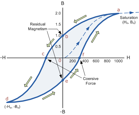
The lag or delay of a magnetic material known commonly as Magnetic Hysteresis, relates to the magnetisation properties of a material by which it firstly becomes magnetised and then de-magnetised.
The set of magnetisation curves, M above represents an example of the relationship between B and H for soft-iron and steel cores but every type of core material will have its own set of magnetic hysteresis curves. You may notice that the flux density increases in proportion to the field strength until it reaches a certain value were it cannot increase any more becoming almost level and constant as the field strength continues to increase.
This is because there is a limit to the amount of flux density that can be generated by the core as all the domains in the iron are perfectly aligned. Any further increase will have no effect on the value of M, and the point on the graph where the flux density reaches its limit is called Magnetic Saturation also known as Saturation of the Core and in our simple example above the saturation point of the steel curve begins at about 3000 ampere-turns per metre.
As the magnetic field strength, ( H ) increases these molecular magnets become more and more aligned until they reach perfect alignment producing maximum flux density and any increase in the magnetic field strength due to an increase in the electrical current flowing through the coil will have little or no effect.
Retentivity
Let’s assume that we have an electromagnetic coil with a high field strength due to the current flowing through it, and that the ferromagnetic core material has reached its saturation point, maximum flux density. If we now open a switch and remove the magnetising current flowing through the coil we would expect the magnetic field around the coil to disappear as the magnetic flux reduced to zero.
However, the magnetic flux does not completely disappear as the electromagnetic core material still retains some of its magnetism even when the current has stopped flowing in the coil. This ability for a coil to retain some of its magnetism within the core after the magnetisation process has stopped is called Retentivity or remanence, while the amount of flux density still remaining in the core is called Residual Magnetism, BR .
The reason for this that some of the tiny molecular magnets do not return to a completely random pattern and still point in the direction of the original magnetising field giving them a sort of “memory”. Some ferromagnetic materials have a high retentivity (magnetically hard) making them excellent for producing permanent magnets.
While other ferromagnetic materials have low retentivity (magnetically soft) making them ideal for use in electromagnets, solenoids or relays. One way to reduce this residual flux density to zero is by reversing the direction of the current flowing through the coil, thereby making the value of H, the magnetic field strength negative. This effect is called a Coercive Force, HC .
If this reverse current is increased further the flux density will also increase in the reverse direction until the ferromagnetic core reaches saturation again but in the reverse direction from before. Reducing the magnetising current, i once again to zero will produce a similar amount of residual magnetism but in the reverse direction.
Then by constantly changing the direction of the magnetising current through the coil from a positive direction to a negative direction, as would be the case in an AC supply, a Magnetic Hysteresis loop of the ferromagnetic core can be produced.
1 Figure
The B-H Curve or Magnetic Hysteresis loop above, shows the behaviour of a ferromagnetic core graphically as the relationship between B and H is non-linear.
Starting with an unmagnetised core both B and H will be at zero, point 0 on the magnetisation curve.
If the magnetisation current, i is increased in a positive direction to some value the magnetic field strength H increases linearly with i and the flux density B will also increase as shown by the curve from point 0 to point a as it heads towards saturation.
Now if the magnetising current in the coil is reduced to zero, the magnetic field circulating around the core also reduces to zero. However, the coils magnetic flux will not reach zero due to the residual magnetism present within the core and this is shown on the curve from point a to point b.
To reduce the flux density at point b to zero we need to reverse the current flowing through the coil. The magnetising force which must be applied to null the residual flux density is called a “Coercive Force”. This coercive force reverses the magnetic field re-arranging the molecular magnets until the core becomes unmagnetised at point c.
An increase in this reverse current causes the core to be magnetised in the opposite direction and increasing this magnetisation current further will cause the core to reach its saturation point but in the opposite direction, point d on the curve.
This point is symmetrical to point b. If the magnetising current is reduced again to zero the residual magnetism present in the core will be equal to the previous value but in reverse at point e.
Again reversing the magnetising current flowing through the coil this time into a positive direction will cause the magnetic flux to reach zero, point f on the curve and as before increasing the magnetisation current further in a positive direction will cause the core to reach saturation at point a.
Then the B-H curve follows the path of a-b-c-d-e-f-a as the magnetising current flowing through the coil alternates between a positive and negative value such as the cycle of an AC voltage. This path is called a B-H Curve or Magnetic Hysteresis Loop.
The effect of magnetic hysteresis shows that the magnetisation process of a ferromagnetic core and therefore the flux density depends on which part of the curve the ferromagnetic core is magnetised on as this depends upon the circuits past history giving the core a form of “memory”. Then ferromagnetic materials have memory because they remain magnetised after the external magnetic field has been removed.
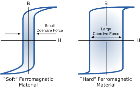
However, soft ferromagnetic materials such as iron or silicon steel have very narrow magnetic hysteresis loops resulting in very small amounts of residual magnetism making them ideal for use in relays, solenoids and transformers as they can be easily magnetised and demagnetised.
Since a coercive force must be applied to overcome this residual magnetism, work must be done in closing the hysteresis loop with the energy being used being dissipated as heat in the magnetic material. This heat is known as hysteresis loss, the amount of loss depends on the material’s value of coercive force.
By adding additive’s to the iron metal such as silicon, materials with a very small coercive force can be made that have a very narrow hysteresis loop. Materials with narrow hysteresis loops are easily magnetised and demagnetised and known as soft magnetic materials.
Magnetic Hysteresis Loops for Soft and Hard Materials
2 Figure
Magnetic Hysteresis results in the dissipation of wasted energy in the form of heat with the energy wasted being in proportion to the area of the magnetic hysteresis loop. Hysteresis losses will always be a problem in AC transformers where the current is constantly changing direction and thus the magnetic poles in the core will cause losses because they constantly reverse direction.
Rotating coils in DC machines will also incur hysteresis losses as they are alternately passing north the south magnetic poles. As said previously, the shape of the hysteresis loop depends upon the nature of the iron or steel used and in the case of iron which is subjected to massive reversals of magnetism, for example transformer cores, it is important that the B-H hysteresis loop is as small as possible.
The classical free electron theory of metals (Drude –Lorentz theory of metals) Drude and Lorentz proposed this theory in 1900. According to this theory, the metals containing the free electrons obey the laws of classical mechanics.
Assumptions ( or salient features) in classical free electron theory
The classical free electron theory is based on the following postulates.
1. The valence electrons of atoms are free to move about the whole volume of the metal, like the molecules of a perfect gas in a container.
2. The free electrons move in random direction and collide with either positive ions fixed to the lattice or the other free electrons. All the collisions are elastic in nature i.e., there is no loss of energy.
3. The momentum of free electrons obeys the laws of the classical kinetic theory of gases.
4. The electron velocities in a metal obey classical Maxwell-Boltzman distribution of velocities.
5. When the electric field is applied to the metal, the free electrons are accelerated in the direction opposite to the direction of applied electric field.
6. The mutual repulsion among the electrons is ignored, so that they move in all the directions with all possible velocities.
7. In the absence of the field, the energy associated with an electron at temperature T is given by  kT. It is related to the kinetic energy equation
 kT =
kT =  v2th
v2th
Here vth represents the thermal velocity.
Success of classical free electron theory
1. It verifies ohm’s law
2. It explains electrical conductivity of metals.
3. It explains thermal conductivity of metals.
4. It derives Widemann – Franz law. (i.e. The relation between electrical and thermal conductivity.
Draw backs of classical free electron theory.
1. It could not explain the photoelectric effect, Compton Effect and black body radiation.
2. Electrical conductivity of semiconductors and insulators could not be explained.
3. Widemann – Franz law (K/σT= constant) is not applicable at lower temperatures.
4. Ferromagnetism could not be explained by this theory. The theoretical value of paramagnetic susceptibility is greater than the experimental value.
5. According to classical free electron theory the specific heat of metals is given by 4.5R whereas the experimental value is given by 3R.
6. According to classical free electron the electronic specific heat is equal to 3/2R while the actual value is 0.01R.
Electrical Conductivity
The classical free electron theory was proposed by Drude and Lorentz. According to this theory the electrons are moving freely and randomly moving in the entire volume of the metal like gas atoms in the gas container. When an electric field is applied the free electrons gets accelerated.
When an electric field E is applied between the two ends of a metal of area of cross section A
When an electrical field (E) is applied to an electron of charge ‘e’ of a metallic rod, the electron moves in opposite direction to the applied field with a velocity vd. This velocity is known as drift velocity.
Drift velocity vd is defined as the average velocity of the free electrons with which they move towards the positive terminal under the influence of the electrical field.
Lorentz force acting on the electron F = eE ........(1)
This force is known as the driving force of the electron.
Due to this force, the electron gains acceleration ‘a’.
From Newton’s second law of motion,
Force F = ma …....(2)
From the equation (1) and (2),
Ma = eE or
a =  …......(3)
Acceleration (a) = 
Or a = 
Relaxation time is defined as the time taken by a free electron to reach its equilibrium position from the disturbed position in the presence of an electric field.
So vd = a ……….(4)
Substituting equation (3) in (4)
vd =  =
=  E ……….(5)
vd =  E ……….(5a)
Where  = RMS velocity
The Ohms’ law states that current density (J) is expressed as
J =E ……….(6)
Or = 
Where is the electrical conductivity of the electron.
But, the current density in terms of drift velocity is given as
J = nevd ....... (7)
Substituting equation (5) in equation (7), we have
J = ne E
E
Or  =
= 
On comparing the equation (6) and (8) , we have
Electrical conductivity
=  ....... (8)
=  ....... (8a)
This is a required expression for electrical conductivity.
Resistivity ρ
ρ =  =
= 
According to kinetic theory of gasses
 =
= 
So =  =
=
Also
ρ =  =
= 
Mobility: It is defined as the drift velocity of the charge carrier per unit applied electric field.
μ=  ....... (9)
From equation (7) we have
J = nevd
By substituting vd =μE from equation (9)
J = neμE
Or  = μne ....... (10)
We know by ohms law =  so equation (10) can be rewritten as
= μne
μ = 
This is the required expression for mobility.
Temperature Dependence
The positive ions are always in oscillating (or vibrating) state about their mean position; even the substance is present at 0k temperature. The vibrating amplitude of ions is always depends the temperature. The mean free path λ of the electrons is inversely proportional to the mean square of amplitude of ionic vibrations A0
λ =  ………(1)
The energy of lattice vibrations is proportional to  and increases linearly with temperature T.
 T ……….(2)
From equations (1) and (2)
λ =  ………..(3)
The resistivity ρ of the metal is inversely proportional to mean free path of electrons λ
ρ =  ..…………..(4)
From equations (3) and (4)
ρ T ..……….(5)
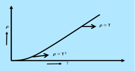
From equation (5) we observe that the resistivity of metal is linearly increases with temperature. The conductivity is defined as the reciprocal of resistance.

 ………….(6)
From equation (6) we observe that the conductivity of metal is inversely proportional to their temperature. The variation of resistivity of metal with temperature is shown in figure.
3 Figure
The microscopic form of Ohm's law is J =σ E, where σ is the electrical conductivity, E the electric field and J the current density.
This form of Ohm's law operates on a microscopic level relating the current density J to the conductivity σ and the electric field E.
We know that the current I = Anevd
Where A is the area of cross-section ,n the number density of electrons, e the charge on each electron and vd the drift velocity of electrons.
Current density J at a point in a conductor is the amount of current flowing per unit area of the conductor around that point provided the area is held in a direction normal to the current.
J = 
Drift velocity vd=  E
E
Where  is the average relaxation time, m is the mass of the charged particle.
So the current I = Anevd = Ane  E =
E = 
 =
= 
i.e. J =  E where resistivity ρ =
 =
=
So
J = E
The microscopic form of Ohm's law.
It was first discovered by the Dutch physicist Heike Kamerlingh Onnes, who was the first to liquefy helium (which boils at 4.2 Kelvin at standard pressure).
In 1911 Kamerlingh Onnes and one of his assistants discovered the phenomenon of superconductivity while studying the resistance of metals at low temperatures. They studied mercury because very pure samples could easily be prepared by distillation. The historic measurement of superconductivity in mercury is shown in Figure.
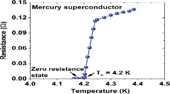
The electrical resistance of mercury decreased steadily upon cooling, but dropped suddenly at 4.2 K, and became undetectably small.
Transition Temperature or Critical Temperature Tc
The temperature at which electrical resistivity of the material suddenly drops to zero and the material changes from normal conductor to a superconductor is called the transition temperature or critical temperature Tc.
Soon after this discovery, many other elemental metals were found to exhibit zero resistance when their temperatures were lowered below a certain characteristic temperature of the material, called the critical temperature, Tc.
Superconductivity
The ability of certain metals, their compounds and alloys to conduct electricity with zero resistance at very low temperature is called superconductivity. The materials which exhibit this property are called superconductors.
Properties
Following properties are shown by superconductors.
- It is a low temperature phenomenon.
- The electrical resistivity drops to zero.
- The conductivity becomes infinity.
- The transition temperature is different for different substances.
- Material having high normal resistivity exhibit superconductivity.
- Materials for which ρZ= 106 (where Z is a atomic number and ρ is resistivity) show superconductivity.
- Superconductivity is very sharp for chemically pure and structurally perfect specimen.
- Ferro magnetic and Anti ferromagnetic materials are not superconductors.
- Below the transition temperature the magnetic flux lines are rejected out of the superconductors.
- Generally Superconducting elements lie in the inner columns of the periodic table.
- Those metallic elements having their valence electrons lies between 2 to 8 exhibit superconductivity.
- Below the transition temperature the specific heat curve is discontinuous.
- There is a discontinuous change in specific heat.
- There are small changes in volume and thermal conductivity of the material.
Types of Superconductors
Based on the diamagnetic response superconductors can be classified into two types, they are
1. Type I superconductors
2. Type II superconductors.
- Type I superconductors
Superconductors which one follows a complete Meissner effect is called type I superconductors. It is also known as soft superconductors.
When the magnetic field strength is gradually increased from its initial value H < HC at HC the diamagnetism is abruptly disappear and the transition from superconducting state to normal state is sharp as shown in figure. These superconductors are known as soft superconductors.
Examples: - Al, Zn, Hg and Sn
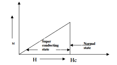
4 Figure Type I superconductors
2. Type II superconductors
Superconductors which does not follow the complete Meissner effect is called type I superconductors. It is also known as hard superconductors.
In type II superconductors, the specimen is in pure superconducting state up to the field HC1 (lower critical field) when the field is increased beyond HC2 (upper critical state) the magnetic flux lines start penetrating.
The specimen is in mixed state between HC1 and HC2. Above HC2, the specimen is in normal state. This means that the Meissner effect is incomplete in the region between HC1 and HC2. This region is known as vertex region. These superconductors are known as hard superconductors.
Examples: - Zr, Nb
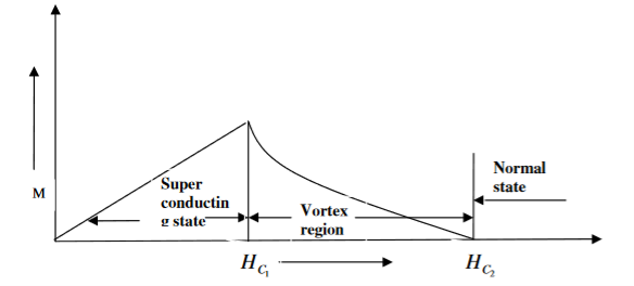
5 Figure Type II superconductors
Differences between type I and Type II superconductor
Type I superconductor | Type II superconductor |
1. It follows complete Meissner effect. | 1. It does not follow the complete Meissner effect |
2. It has single critical field valueHC | 2. It has two critical field values HC1 and HC2. |
3. There no mixed state. | 3. There is a mixed state |
4. They are soft superconductors | 4. They are hard superconductors |
5. Materials with pure form are type I superconductors | 5. Materials with impurities or alloys are type II superconductors |
Applications of Superconductors
- Superconductors form the basis of energy saving power systems, namely the superconducting generators, which are smaller in size and weight, in comparison with conventional generators.
- Superconducting magnets have been used to levitate trains above its rails. They can be driven at high speed with minimal expenditure of energy.
- Superconducting magnetic propulsion systems may be used to launch satellites into orbits directly from the earth without the use of rockets.
- High-efficiency ore-separating machines may be built using superconducting magnets which can be used to separate tumour cells from healthy cells by high gradient magnetic separation method.
- Since the current in a superconducting wire can flow without any change in magnitude, it can be used for transmission lines.
- Superconductors can be used as memory or storage elements in computers.
In 1933, Walter Meissner and Robert Ochsenfeld discovered a magnetic phenomenon that showed that superconductors are not just perfect conductors.
When a weak magnetic is applied to a superconducting specimen at a temperature below transition temperature Tc the magnetic flux lines are expelled. This phenomenon is called Meissner effect.
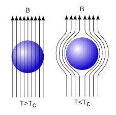
Under normal state the magnetic induction inside the specimen is
B = μ0(H+I)
Where H is the external applied magnetic field and I is the magnetization produced inside the specimen.
When the specimen is in superconducting state B=0 (Meissner effect)
B = μ0(H+I)
0 = μ0(H+I)
H= -I
χ = H/I =-1
Thus the material is act as a perfectly diamagnetic because for diamagnetic material susceptibility χ = -1 .
Let us consider a superconducting material is in normal state. From ohms law, the electric field E=Jρ
On cooling the material to its transition temperature ρ tends to zero. If J is held finite E must be zero. From Maxwell’s equations
∇ × E = - dB / dt
Under superconducting condition
Since E is zero
DB/dt =0
Or B=constant.
This means that the magnetic flux passing through the specimen should not change on cooling to the transition temperature. The Meissner effect contradicts the result.
Application of Meissner Effect
This effect of superconductivity is used in magnetic levitation which is the base of modern high-speed bullet trains. In superconducting state (phase), due to expulsion of external magnetic field, the sample of superconducting material levitates above magnet or vice-versa. Modern high-speed bullet trains use the phenomenon of magnetic levitation.
The Band Theory of Solids
Bands are formed by the closely spaced orbitals.
There are three types of bands:
1. Valance Bands: Valence band it is a group of orbitals which contain electrons in the shell. Or we can say It is also defined as the energy band that comprises of valence electrons present in the outermost shell of an atomic structure.
These valence electrons, when provided with sufficient energy, get changed into free electrons and moves to conduction band thereby causing conductivity. It is at a lower energy level than the conduction band in the energy level diagram.
2. Conduction Band: Conduction band is a group of empty orbitals of the shells that do not contain any electron due to their configuration making the orbitals of higher energy levels.
When the electrons pass from valance band to the conduction band these solids conduct electricity with flow of charges in the form of electrons.
3. Forbidden Energy Band: These two bands are separated by a certain amount of energy known as the forbidden energy gap. In this band not a single electron is available. It diagram it is named as Band Gap.
Let us distinguish between conductor, semiconductors and insulator on the basis of these bands
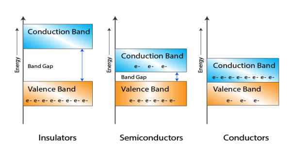
6 Figure: Energy band in insulator, conductor and semiconductor
- In Conductors: The valance band and the conduction band overlap each other. This makes it easy for the electricity to pass through them. In conductors, the valence band is either not fully occupied with electrons, or the filled valence band overlaps with the empty conduction band. In general, both states occur at the same time, the electrons can therefore move inside the partially filled valence band or inside the two overlapping bands. In conductors there is no band gap between the valence band and conduction band.
- In Semi-conductors: there is a slight gap between the conduction band and the valance band. This band gap is less than or equal to 1.4 eV. The electrons from valance shell take a little energy to excite from valance band to the conduction band. Even in semiconductors, there is a band gap, but compared to insulators it is so small that even at room temperature electrons from the valence band can be lifted into the conduction band. The electrons can move freely and act as charge carriers.
- In Insulators: In insulators the valence band is fully occupied with electrons due to the covalent bonds. To achieve conductivity, electrons from the valence band have to move into the conduction band. The energy gap is considerably large and the electrons of the valance band cannot be excited to the conduction band before the melting or the dissociation of the solid. This means that under the practically ambient condition it cannot conduct electricity.
Consider an isolated silicon atom; its energy levels are quantized. When two identical atoms are brought closer together, the quantized energy levels hybridize and split into two different levels because of the mutual interaction of the two atoms. More generally, when N atoms are moved closer, until they reach the equilibrium inter-atomic distance d, the energy levels split into N levels. These N levels are very close to each other if N is large (which is the case in a crystal) so that they eventually form a continuous energy band.
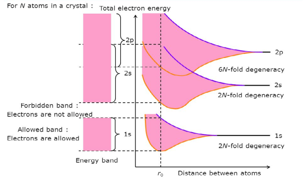
7 Figure: Formation of Energy band as a function of interatomic distance (distance between atoms)
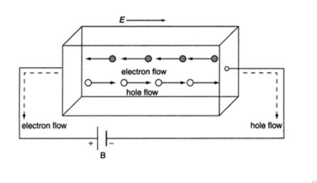
In semiconductor, the conduction band electron and valance band hole participate in electrical conduction. To obtain expression for electrical conductivity consider an intrinsic semiconductor bar which is connected to external battery as shown in figure
The electric field exist along x direction. The field accelerate electrons (conduction electrons) along negative X-direction and holes along positive X-direction. They starts moving with a constant velocity called Drift velocity vd
The total current in the semiconductor (due to both electron and hole)
I = Ie +Ih
Or total current density
J = Je +Jh ..........(1)
8 Figure
In order to find the current density of electrons, let the concentration of electrons are 'n' , charge is 'e' and drift velocity is 've', Then
Je =neve ..........(2)
The drift velocity produced per unit elctric feild is called 'mobility' , Thus
μe = 
Or
μeE = 
Substituting in equation 2
Je =neμeE ..........(3)
From Ohms law,
J = E where Je = eE
Je =neμeE = eE ..........(4)
e = neμe ..........(5)
Similarly current density for holes
Jp =peμpE = pE ..........(6)
And conductivity
p = peμp ..........(7)
Substituting value of Je and Jp from eq 4 and 6 in eq 1, we get
J = neμeE + peμpE
J = (neμe + peμp)E ..........(8)
From Ohms law J = E
= neμe + peμp
Where e = neμe and p = peμp
Also ni =CT3/2e -Eg/2kT ..........(9)
Therefore
= nie(μe + μp) = CT3/2e -Eg/2kT e(μe + μp) ..........(10)
The mobilities of carrier depend upon temperature as
μ 

For Electrons μe
 and for holes μp

μe + μp= =
=  ..........(11)
Using equation 11 in equation 10
= CT3/2e -Eg/2kT e
= C e e -Eg/2kT
Let B = C e we get
= Be -Eg/2kT ..........(12)
When magnetic field is applied perpendicular to a current-carrying conductor, then a voltage is developed in the material perpendicular to both magnetic field and current in the conductor. This effect is known as Hall Effect and the voltage developed is known as Hall voltage (VH).
Hall Effect is useful to identify the nature of charge carriers in a material and hence to decide whether the material is n-type semiconductor or p-type semiconductor, also to calculate carrier concentration and mobility of carriers.
Hall Effect can be explained by considering a rectangular block of an extrinsic semiconductor in which current is flowing along the positive X-direction and magnetic field B is applied along Z-direction as shown in Figure.
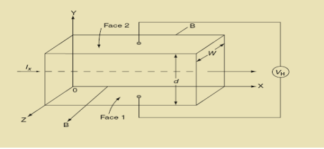
9 Figure: Hall Effect
Suppose if the semiconductor is n-type, then mostly the carriers are electrons and the electric current is due to the drifting of electrons along negative X-direction or if the semiconductor is p-type, then mostly the carriers are holes and the electric current is due to drifting of the holes along positive X-direction.
As these carriers are moving in magnetic field in the semiconductor that mean they experience Lorentz force represented by FL
FL = Bevd
Where vd is the drift velocity of the carriers. (already explained in previous section).
We can obtain the direction of this force by applying Fleming’s left-hand rule in electromagnetism.
Fleming’s left-hand rule can be explained as If we stretch the thumb, fore finger and middle finger in three perpendicular directions so that the fore finger is parallel to the magnetic field and the middle finger is parallel to the current direction, then thumb represents the direction of force on the current-carrying carriers.
So the Lorentz force is exerted on the carriers in the negative Y-direction. Due to Lorentz force, more and more carriers will be deposited at the bottom face (represented by face 1in figure) of the conductor.
The deposition of carriers at the bottom face is continued till the repulsive force due to accumulated charge balances the Lorentz force.
After some time of the applied voltage, both the forces become equal in magnitude and act in opposite direction, then the potential difference between the top and bottom faces is equal to Hall voltage and that can be measured.
At equilibrium, the Lorentz force on a carrier
FL = Bevd ……………..(1)
And the Hall force
FH = eEH ……………..(2)
Where EH is the Hall electric field due to accumulated charge.
At equilibrium, FH = FL
EEH = Bevd
∴ EH = Bvd ……………..(3)
If ‘d’ is the distance between the upper and lower surfaces of the slab, then the Hall field
EH =  ……………..(4)
In n-type material, Jx = –nevd
vd = -  ……………..(5)
Where n is free electron concentration, substituting (5) in (3), we have
∴ EH = -B  ……………..(6)
For a given semiconductor, the Hall field EH is proportional to the current density Jx and the intensity of magnetic field ‘B’ in the material.
i.e. EH ∝ JxB
(or) EH = RHJxB ……………..(7)
Where RH = Hall coefficient
Equations (6) and (7) are same so, we have
RHJxB =-B 
RH = -  = -
= -  ……………..(8)
Where ρ is charge density
Similarly for p-type material
RH =  =
= ……………..(9)
Using Equations (8) and (9), carrier concentration can be determined.
Thus, the Hall coefficient is negative for n-type material. In n-type material, as more negative charge is deposited at the bottom surface, so the top face acquires positive polarity and the Hall field is along negative Y-direction. The polarity at the top and bottom faces can be measured by applying probes.
Similarly, in case of p-type material, more positive charge is deposited at the bottom surface. So, the top face acquires negative polarity and the Hall field is along positive Y-direction. Thus, the sign of Hall coefficient decides the nature of (n-type or p-type) material.
The Hall coefficient can be determined experimentally in the following way:
Multiplying Equation (7) with ‘d’, we have
EHd = VH = RHJxBd ……………..(10)
From (Figure 11) we know the current density Jx
Jx = 
Where W is width of the box. Then, Equation (10) becomes
VH = RH Bd = RH
RH =  ……………..(11)
Substituting the measured values of VH, Ix, B and W in Equation(11), RH is obtained. The polarity of VH will be opposite for n- and p-type semiconductors.
The mobility of charge carriers can be found by using the Hall effect, for example, the conductivity of electrons is
n = neμn
Or we can rewrite it as
μn =  =n RH ……………..(12)
By using equation (11)
μn = n ……………..(13)
Applications of Hall Effect
- For determination of type of given semiconductor.
For N-type, Hall coefficient RH= negative
For P-type, Hall coefficient RH= Positive
- To determine carrier concentration n and p; that is n=p=1/e𝑅𝐻
- Determination of mobility of charge carriers μn =
 =n RH. Where 𝜎= electrical conductivity
 - To determine the sign of charge carriers whether the conductivity is due to electrons or holes.