|
# In case of capacitor: -
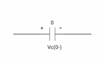
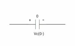
At time t= 0-
|
:. Capacitor is initially uncharged
Q (0- ) =0
Q = CV
Q (0-) = CVc (0-)
Vc (0-) =0
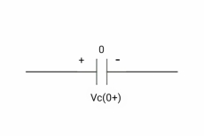
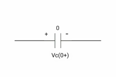
At time t= 0+
|
By low of conservation of charges
Q (0- ) = Q (0+)
Cvc (0-) =cvc (0+)
Vc (0+) =0
Hence acts as
|
If capacitor is initially uncharged at t= 0- than voltage across capacitor is zero at t=0+ capacitor will follow low of consvation of charges and VC (0+) =0 it means at t=0+ capacitor behaves as short circuit in other words, voltage across capacitor cannot change instantaneously.
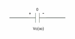
At time t= infinity,
|
I = cdvc/dt constant and maximum
Hence, i= 0
At t= infinity capacitor will be fully charged or voltage across capacitor is constant and current through capacitor is zero so, capacitor will behave as open –circuit
Say capacitor is initially charged
|
At time t= 0-,
|
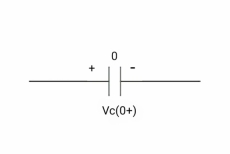
At time t= 0+,
|
At time t= 0+
|
Q (0- ) = Q (0+)
Cvc (0- ) =cvc (0+)
V1 = Vc (0+)
|
Hence acts as
|
Its capacitor is initially charged at t= 0- as voltage across capacitor is V1 than at t=0+ capacitor behaves as a voltage as a voltage source with value V1
At time t = infinity
|
If capacitor is initially charged and it is connected to any independent source for long time than current through capacitor is 3 farads and capacitor will be fully charged and it behaves as o.c
For Inductor: -
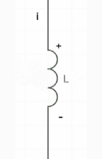
At time t= 0-
|
Ø= Li =0
Ø (0) = Li (0-)
i (0-) =0
at t= 0+,
|
by low of conservation of flux
Ø (0-) = Ø (0+)
Li (0-) = Li (0+)
0 =i (0+)
Hence, acts as short circuit
Electronic systems are built around analog and digital components. They comprise resistors, capacitors, diodes, inductor, operational amplifiers and transistors. These components are often called active and passive elements. Majority of the analog circuits consist passive and active ones that are responsible for power management.
What is an Active element?
Active components control the charge flow in electronic circuits. It is the core component to operate any device. The two parameters to consider for proper device operation are current and voltage. Hence the voltage and current in a circuit may be boosted or stepped down based on the flow of electrons injected by an active device. Components like Diodes, Transistors, voltage operated devices, Vacuum tubes, voltage and current sources comes under active elements. An active component without doubt, amplifies the power of a signal (voltage or current). Transistor is a good example that acts as an amplifier in radio and RF circuits.
In addition, active elements are categorised into two sections. They are voltage controlled and current controlled sources. Voltage controlled devices produce their output current depending upon the input voltage. BJT (Bipolar junction transistor) is a voltage controlled device which supplies static voltage as a control signal.
What is Passive element?
Passive elements are quite opposite to active ones. They don’t require any external voltage to perform their job. Examples: Resistor, Capacitor, Inductor etc.
But they are not capable to provide energy on their own. They require assistance from active devices. For example, a resistor is a versatile component used as pull up or pulls down resistor in most of the hardware design.
We can use the pull-up and pull-down as control signal from the microcontroller interrupt to turn and turn off external devices. Inductors and capacitors have the capability to store energy for longer time and discharge.
Ideal and practical Voltage and Current source:
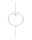
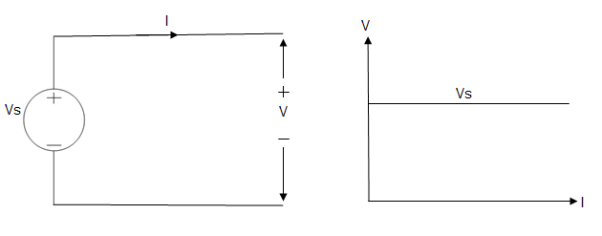
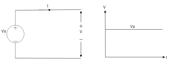
A voltage source is a device which provides a constant voltage to load at any instance of time and is independent of the current drawn from it. This type of source is known as an ideal voltage source. Practically, the ideal voltage source cannot be made. It has zero internal resistance. It is denoted by this symbol.
|
Fig: Voltage source symbol
|
Fig: Ideal Voltage Source
The graph represents the change in voltage of the voltage source with respect to time. It is constant at any instance of time.
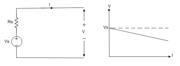
Voltage sources that have some amount of internal resistance are known as a practical voltage source. Due to this internal resistance, voltage drop takes place. If the internal resistance is high, less voltage will be provided to load and if the internal resistance is less, the voltage source will be closer to an ideal voltage source. A practical voltage source is thus denoted by a resistance in series which represents the internal resistance of source.
Practical Voltage source
|
Fig: Practical Voltage source
The graph represents the voltage of the voltage source with respect to time. It is not constant but it keeps on decreasing as the time passes.
Current source
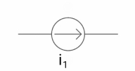
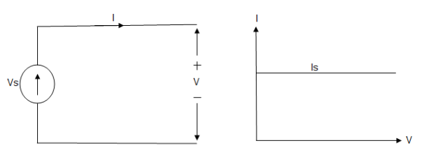
A current source is a device which provides the constant current to load at any time and is independent of the voltage supplied to the circuit. This type of current is known as an ideal current source; practically ideal current source is also not available. It has infinite resistance. It is denoted by this symbol.
Ideal Current source
|
Fig: Ideal Current source
The graph represents the change in current of the current source with respect to time. It is constant at any instance of time.
Why ideal Current source has infinite resistance?
A current source is used to power a load, so that load will turn on. We try to supply 100% of the power to load. For that, we connect some resistance to transfer 100% of power to load because the current always takes the path of least resistance. So, in order for current to go to the path of least resistance, we must connect resistance higher than load. This is why we have the ideal current source to have infinite internal resistance. This infinite resistance will not affect voltage sources in the circuit.
Practical Current source
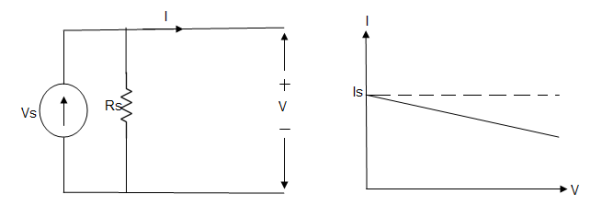
Practically current sources do not have infinite resistance across there but they have a finite internal resistance. So the current delivered by the practical current source is not constant and it is also dependent somewhat on the voltage across it.
A practical current source is represented as an ideal current source connected with resistance in parallel.
|
Fig; Practical Current source
The graph represents the current of the current source with respect to time. It is not constant but it also keeps on decreasing as the time passes.
Examples of current and voltage sources
The examples of current source are solar cells, transistors and examples of some voltage sources are batteries and alternators.
This was all about ideal and practical sources of power. The ideal sources are very useful for calculations in theory but as ideal sources are not practically possible, only practical sources are used in practical circuits. The batteries we use are a practical source of power and the voltage and current decreases as we use it. Thus both are useful to us in their own ways.
|
|
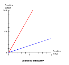
The gain or amplification factor determines the slope of the line. The steeper the slope the greater the gain. The amplifier depicted in red lines has more gain than one depicted by blue line.
Linear network:
In simple words, a linear circuit is an electric circuit in which circuit parameters Resistance, inductance, capacitance, waveform, frequency etc are constant. In other words, a circuit whose parameters are not changed with respect to Current and Voltage is called Linear Circuit.
Linear literally means along with a straight line. The linear characteristics in between current and voltage means current flowing through a circuit is directly proportional to the applied Voltage.
If we increase the applied voltage, then the current flowing through the circuit will also increase, and vice versa. If we draw the circuit output characteristic curve in between current and voltage, it will look like a straight line.
The conduction of current in both directions in an element, (Resistance Inductance and Capacitance) with same magnitude is termed as bilateral element.
|
Unilateral element:
The conduction of current in one direction is termed as unilateral element. Example: Diode, Transistor.
In RLC circuit, the most fundamental elements of a resistor, inductor and capacitor are connected across a voltage supply. All of these elements are linear and passive in nature. Passive components are ones that consume energy rather than producing, linear elements are those which have a linear relationship between voltage and current.
There are number of ways of connecting these elements across voltage supply, but the most common method is to connect these elements either in series or in parallel.
The RLC circuit exhibits the property of resonance in same way as LC circuit exhibits, but in this circuit the oscillation dies out quickly as compared to LC circuit due to the presence of resistor in the circuit.
Series RLC Circuit
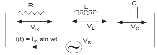
When a resistor, inductor and capacitor are connected in series with the voltage supply, the circuit is called series RLC circuit. Since all these components are connected in series, the current in each element remains the same,
IR=IL=IC=I(t) where I(t)=IM sin𝛚t
|
Let VR be the voltage across resistor, R.
VL be the voltage across inductor, L.
VC be the voltage across capacitor, C.
XL be the inductive reactance.
XC be the capacitive reactance
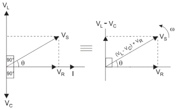
The total voltage in RLC circuit is not equal to algebraic sum of voltages across the resistor, the inductor and the capacitor; but it is a vector sum because, in case of resistor the voltage is in-phase with the current, for inductor the voltage leads the current by 90o and for capacitor, the voltage lags behind the current by 90o.
So, voltages in each component are not in phase with each other; so they cannot be added arithmetically. The figure below shows the phasor diagram of series RLC circuit
VS2=VR2+(VL-VC)2 if VL>VC
Where VR=IR,VL=IXL,VC=IXC
|
The Impedance for a Series RLC Circuit
|
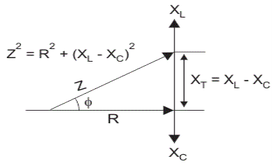
The impedance Z of a series RLC circuit is defined as opposition to the flow of current due circuit resistance R, inductive reactance, XL and capacitive reactance, XC. If the inductive reactance is greater than the capacitive reactance i.e. XL > XC, then the RLC circuit has lagging phase angle and if the capacitive reactance is greater than the inductive reactance i.e. XC > XL then, the RLC circuit have leading phase angle and if both inductive and capacitive are same i.e. XL = XC then circuit will behave as purely resistive circuit.
We know that
VS2=VR2+(VL-VC)2
Where,
VR=IR, VL=IXL, VC=IXC
Substituting the values
VS2=IR2+ (IXL-IXC)2
Where VS=I√R2+(XL-XC)2 OR Impedance Z= R2+(XL-XC)2
Parallel RLC Circuit
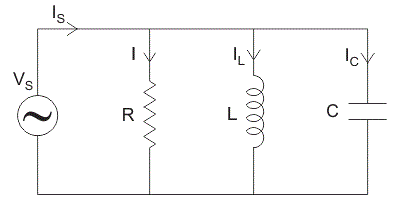
In parallel RLC Circuit the resistor, inductor and capacitor are connected in parallel across a voltage supply. The parallel RLC circuit is exactly opposite to the series RLC circuit. The applied voltage remains the same across all components and the supply current gets divided.
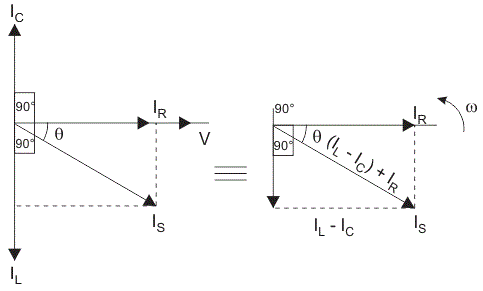
The total current drawn from the supply is not equal to mathematical sum of the current flowing in the individual component, but it is equal to its vector sum of all the currents, as the current flowing in resistor, inductor and capacitor are not in the same phase with each other, so that they cannot be added arithmetically.
|
Phasor diagram of parallel RLC circuit, IR is the current flowing in the resistor, R in amps.
IC is the current flowing in the capacitor, C in amps.
IL is the current flowing in the inductor, L in amps.
Is is the supply current in amps.
In the parallel RLC circuit, all the components are connected in parallel; so the voltage across each element is same. Therefore, for drawing phasor diagram, take voltage as reference vector and all the other currents i.e. IR, IC, IL are drawn relative to this voltage vector.
The current through each element can be found using Kirchhoff’s Current Law, which states that the sum of currents entering a junction or node is equal to the sum of current leaving that node.
|
IS2=IR2+ (IL-IC)2
Now , IR=V/R,IC=V/XC, IL=V/XL
IS=√V2/R2+ (V/XL-V/XC)2
So admittance, 1/Z=IS/V=Y=√1/R2+ (1/XL-1/XC)2
As shown above in the equation of impedance, Z of a parallel RLC circuit; each element has reciprocal of impedance (1 / Z) i.e. admittance, Y. So in parallel RLC circuit, it is convenient to use admittance instead of impedance.
Formula for Resonant Frequency
During resonance, at certain frequency called resonant frequency, fr.
XL=XC
We know that
XL=2πfL and XC=1/2πfC
Therefore, at resonant frequency, fr
2πfrL=1/2πfrC
When resonance occurs, the inductive reactance of the circuit becomes equal to capacitive reactance, which leads to minimum circuit impedance for series RLC circuit.
When resistor, inductor and capacitor are connected in parallel, maximum circuit impedance can be achieved for parallel RLC circuit, hence it is termed as anti-resonator.
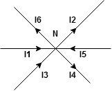
The algebraic sum of currents meeting at a junction or node in an electric circuit is zero or the summation of all incoming current is always equal to summation of all outgoing current in an electrical network.
Explanation
|
Assuming the incoming current to be positive and outgoing current negative we have
|
I e incoming current = ∑ outgoing current thus, the above Law can also be stated as the sum of current flowing towards any junction in an electric circuit is equal to the sum of currents flowing away from that junction
Kirchhoff’s Voltage Law (KVL)
Statement: The algebraic summation of all Voltage in any closed circuit or mesh of loop zero.
i.e. ∑ Voltage in closed loop = 0 the summation of the Voltage rise (voltage sources) is equal to summation of the voltage drops around a closed loop in 0 circuit for explanation from here.
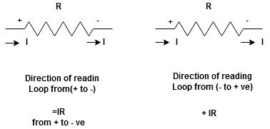
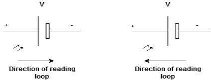
Determination of sigh and direction of currents (Don’t write in exams just for understanding)
|
Current entering a resistor is +ve and leaving should be –ve
now
Potential Rise Potential Drop
We are reading from +V to –V we are reading from –V to +V
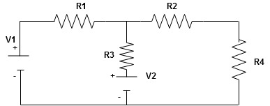
Given Circuit
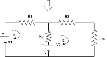
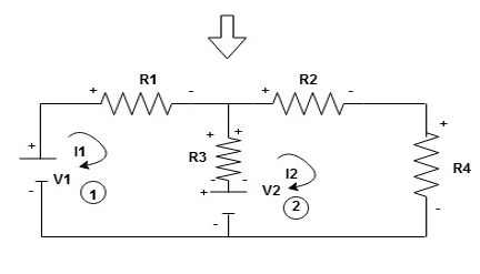
First identify no of loops and assign direction of current flowing in loop Note: no of loops in circuit = No, of unknown currents = no, of equations in the circuit
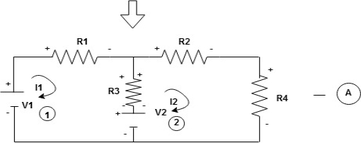
Note: keep loop direction and current direction same i.e. either clockwise or anticlockwise for all loops I1 I2 Now according to direction of direction assign signs (+ve to –ve) to the resistors
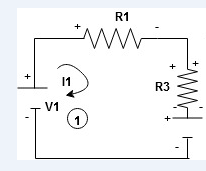
Note: voltage sources (V) polarities do not change is constant. Note: for common resistor between 2 loops appearing in the circuit like R3 give signs according to separate loops as shown
When considering only loop no 1 (+ R3 - )
|
Now consider diagram A and write equations
Two loops  two unknown currents
  two equation
Apply KVL for loop ① [B. Diagram]
(+ to drop -) = - sign and (- to rise +) = + sign
 for drop = -sign
 for rise = + sign
-
-( ) R2 is considered because in R3,2 currents are flowing
  and
and  and we have taken (
 ) because we are considering loop no 1 and current flowing is
  in loop no 1
 )
)
Similarly for loop no. 2 currents flowing is  resistor R3 it should be
  )R3
)R3
|
Consider loop no. 1 apply KVL
- …….①
…….①
-
Consider loop no. 2 apply KVL
- …….②
…….②
-
After solving equation ① and ② we will get branch current  and
and 
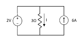
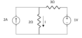
This is only applicable to circuits with linear elements.
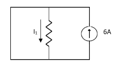
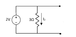
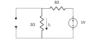
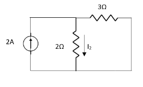
If two or more than two independent sources (voltage or current) are operating in the circuit than voltage across any element or current through any element is sum of current and voltages due to individual sources.
Question 1. Find the current through  resistance.
|
Solution:
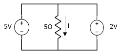
Special Case:
|
Since two voltage sources with different magnitude in parallel which cannot be connected as in single branch two different current is not possible (if 5V than I = zero).
Question:
=
=
|
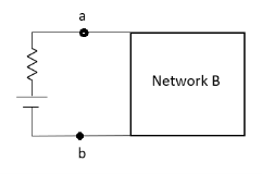
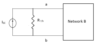
Thevenin’s equivalent of A Norton’s equivalent of A
|
- Norton’s equivalent is obtained by source conversion of thevenin’s equivalent circuit.
CONDITIONS FOR APPLICATION
- For network A:
- Network A should contain linear elements.
- Network A can have independent and dependent current and voltage source.
- If network A has dependent source than controlling parameter must lie within network ‘A’.
- Network A should not have any source coupling and magnetic coupling.
- For network B:
- It can have linear and nonlinear elements.
- It can have dependent and independent voltage and current sources.
- It should not have any source and magnetic coupling with network A.
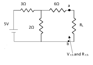
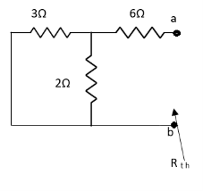
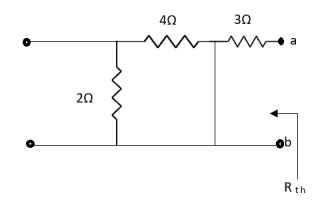
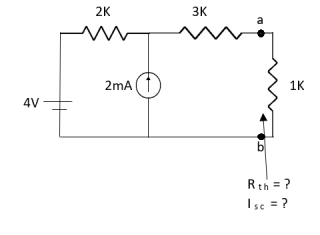
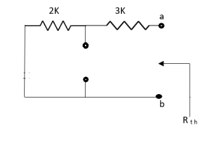
- Method for finding Rth :
Firstly, open circuit terminal A and B.
- If network is operating with only independent sources:
- Make all sources zero in network A.
- Find out the equivalent resistance across terminal A and B.
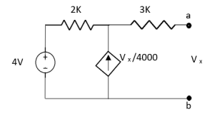
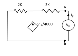
2. If network A is operating with independent and dependent sources:
- Make all independent sources zero in network A.
- Connect a generation between A and B.
3. If network is operating with only dependent sources:
Connect generation between A and B

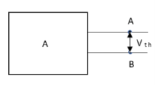
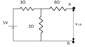
- Method for Vth:
First open circuit terminal A and B.
Find out the voltage between A and B this is Vth
|
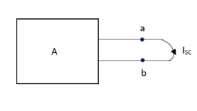
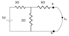
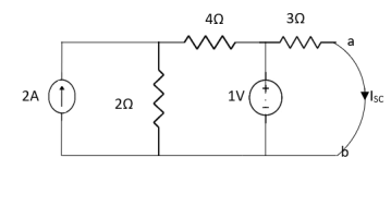
- Method for Isc:
- Isc =

- Remove network B and S.C. the terminal A and B and current from terminal A to B Isc.
|
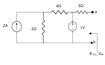
Question:
|
Answer:
Finding Isc from circuit directly:
By KCL,
|
Question:
|
Answer
Also, clear from circuit that Vth = 1V.
By applying KVL we get, 1-3Isc=0 Isc=
|
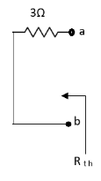
Que:
|
Ans;
Rth=3k+2k=5k By applying KVL we get Therefore,
|
Question:
|
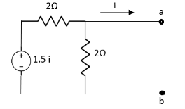
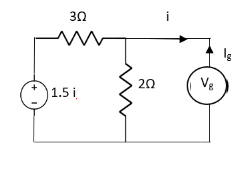
Solution: For Rth
By KCL, But,
By KVL,
|
Question:
|
Solution:
Since, no independent source is present so, Isc = 0 And we know that,
Since Rth cannot be zero
But
|
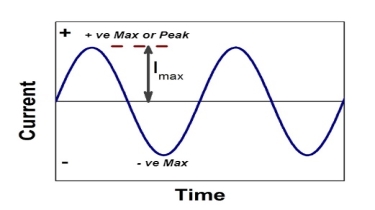
AC Fundamentals necessary to analyse the networks consisting of various alternating current and voltage sources, resistances and inductive, capacitive reactances. An alternating current or voltage is the one which changes periodically both in Cycle magnitude and direction. Such Change in magnitude and direction is measured in terms of cycles.
Each cycle of AC Fundamentals consists of two half cycles’ namely positive cycle and negative cycle. Current increases in magnitude, in one particular direction, attains maximum and starts decreasing, passing through zero it increases in opposite direction and behaves similarly. The value of an alternating quantity at a particular instant is called its instantaneous value
Each repetition of a set of positive and negative instantaneous values of an alternating quantity is called a cycle. The time taken by an alternating quantity to complete its one cycle is known as its time period denoted as T seconds. The number of cycles completed by an alternating quantity per second is known as its frequency. It is denoted by ‘f’ and measured in cycles/second i.e. Hertz (Hz). As the time period is the time required to complete one cycle, we can write,
f=1/T Hz
The maximum value attained by an alternating quantity during positive or negative half cycle is called its amplitude. The mathematical equation giving the instantaneous value of an alternating voltage is given by,
e=Em sin𝛉=Em sin𝛚t
where Em=maximum or peak value of voltage
𝛚=2πf
t=time in seconds
Similarly, an alternating current can be expressed as,
i=Im sin𝛚t
The maximum or peak value is nothing but the amplitude of an alternating quantity. In practice the alternating quantities are expressed interim of their r.m.s. values. The relation between r.m.s value and the maximum value is,
Rms=Vm/√2 and Rims=Im/√2
The r.m.s values are denoted by the capital letters as V or I. Practically in AC Fundamentals analysis, most of the currents and voltages are not in phase but have some phase difference in between them. If current lags the voltage by angle φ then its mathematical equation is,
i=Im sin(ωt-∅)
While if current leads the voltage by angle φ then it is expressed as,
i=Im sin(ωt-∅)
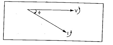
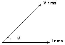
The alternating quantities are conveniently represented by the phasor diagrams. The phasor diagram is basically a polar representation of an alternating quantity. The phasors rotate in anticlockwise direction with an angular velocity ω rad/sec. All the phasors representing various alternating quantities have a particular fixed position with respect to each other. For example if there is a voltage,
V=Vm sin (ωt)
And current i=Im sin (ωt-∅)
|
Then the corresponding phasor diagram representing this voltage and current is shown in above figure, In such a case we say that the current lags voltage by angle φ
Similarly consider voltage as v = Vm sin ωt and the current as,
i=Im Sin (ωt+∅)
Remember that while deciding lagging or leading nature of the current, the direction of rotation of phasors is always anti clockwise. The various current and voltage phasors can be represented in polar form or rectangular form.
Consider a general equation of an alternating quantity as,
e=Em sin (ωt±∅)
In a polar co-ordinate system, to define a particular point, it requires a magnitude and a phase angle. So given alternating voltage can be represented with a phasor of magnitude Em and an angle ± φ in a polar co-ordinate system
|
Hence in polar co-ordinate system, an alternating quantity is represented as,
E=Em<+∅° or Em<-∅°
Generally instead of magnitude Em the r.m.s. value of an alternating quantity is used.
Thus if φ = 0° i.e. e = Em sin ωt with its r. m.s. value as E volts then it is represented in polar form as,
Polar form =E<0° Volts
This phasor lies along x-axis.
Similarly an alternating current also can be represented in the polar form.
i=Im Sin (ωt±∅)
Polar form =I<±∅
Where I=rms value of current
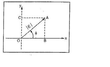
Now consider a phasor shown in below fig. In polar form it is represented as
E<±φ
|
The point A can be represented in the rectangular form with x co-ordinate and y co-ordinate
OB=OA Cos∅=E Cos∅=x co-ordinate
While, OC=OA Sin∅=E Sin∅=y co-ordinate
The y axis is an imaginary axis and hence in rectangular form the phasor OA is represented as, rectangular form = E cos φ + j.E sin φ
Thus if φ = 0 then the y co-ordinate of the corresponding quantity is also zero.
Thus in polar form if quantity is represented as E∠±φ then its rectangular form is E cosφ ± j E sin φ.
In general, r<±θ=(real part)+j(imaginary part)
=r cosθ±j r sinθ
If the rectangular form is known then the magnitude and phase in polar form can be obtained as,
|
If there are two alternating quantities as,
Then the addition or subtraction of the two is done in the rectangular form as,
While multiplication or division of the two is done in the polar form as,
The addition and subtraction of the phasors must be done in rectangular form while the multiplication and division of the phasors must be done in the polar form
|
Peat to peak value:
The value of an alternating quantity from its positive peak to negative peak

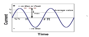
Average Value:
|
The arithmetic mean of all the value over complete one cycle is called as average value

 =
= 
For the derivation we are considering only hall cycle.
Thus  varies from 0 to ᴫ
i = Im Sin


Solving
We get


Similarly, Vavg=
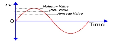
The average value of sinusoid ally varying alternating current is 0.636 times maximum value of alternating current.
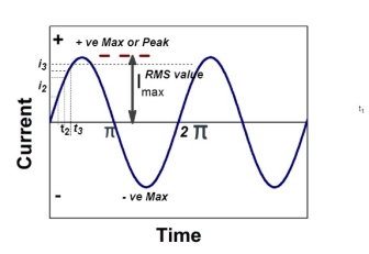
RMS value: Root mean square value
|
The RMS value of AC current is equal to the steady state DC current that required producing the same amount of heat produced by ac current provided that resistance and time for which these currents flows are identical.

I rms = 
Direction for RMS value:
Instantaneous current equation is given by
i = Im Sin 
but 
I rms = 
= 
=
=
Solving
=
=
Similar we can derive
V rms=  or 0.707 Vm
 the RMS value of sinusoidally alternating current is 0.707 times the maximum value of alternating current.
Peak factor (kp) (for numerical)
It is the ratio of maximum value to rms value of given alternating quantity
Kp = 
 Kp =
Kp = 
 Kp = 1.414
Form factor (Kf): For numerical “It is the ratio of RMS value to average value of given alternating quality”.


|
|
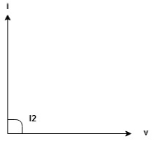
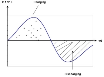
Power P= Ѵ. i
= [Vm Sin ωt] [Im sin (wt + X/2)]
= Vm Im Sin wt Sin (wt + X/2)]
 (cos wt)


 to charging power waveform [resultant].
|
Phasor representation of Sinusoidally varying voltage and current
|
The phases can be represented in different ways
- Polar Form
- Rectangular Form
- Trigonometric Form (P - R)
- Exponential Form (R - P)
|
The instantaneous voltage equation
V(t) = V m sin (w t + Ø)
- Polar Form
The instantaneous voltage equation is given by
Vt= vm sin (w t +Ø)
This can be represented by polar form
vt =  L Ø
L Ø
Where  = peak value
e.g. vt =30 sin (w t + 90 )
)
Polar form  < 90
< 90
Polar form is suitable for multiplication and division of phases.
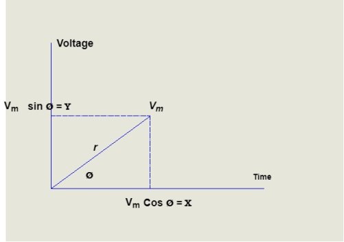
2. Rectangular Form:
The instantaneous voltage equation is given by
Vt = v m sin (w t +Ø)
This can be represented by Rectangular Form
vt = 
Where X =  or Vm cos Ø
Y = or Vm sin Ø
Vt = v m cos Ø + i vm sin Ø
e.g. 30 sin (w t + 90)
Rectangular form vt = 30 cos 90 + i 30 sin 90
 Rectangular Form is suitable for addition and subtraction of Phases.
3. Trigonometric Form (Polar to Rectangular)
If the phases are given in polar form from  L Ø then it can be represented in
rectangular form by expressing X and Y component in form of  and Ø.
Polar: Vt =  L Ø
L Ø
Rectangular: vt=  + i
+ i where
where
𝑥 =  cos Ø
cos Ø
𝑦 =  sin Ø
sin Ø

4. Exponential Form (R-P)
Given equation Rect :v(+) =𝑥 + i𝑦
Polar: v(+) = 
Where magnetite 
And 
2 Phase added and substrate using Rect. Form
Let V1 = 𝑥1 + i𝑦1
V2 = 𝑥2 + i𝑦2
 (V1 + V2) = (𝑥1 + i𝑦1) + (𝑥2 + i𝑦2)
= (𝑥1 + 𝑥2) + i(𝑦1 + 𝑦2)
(V1 – V2) = (𝑥1 – 𝑥2) + i(𝑦1 - 𝑦2)
For add or subst. If eqtn. Is given in polar form, we have to connect into Rect. Form and then add/ subtract.
Two phases divide/ multiply by polar
Let V1 = π1 L Ø1
Let V2 = π2 L Ø2
(V1 V2) = (π1 L Ø1) (π2 L Ø2)
 (V1 X V2) = (π1 x π2) L (Ø1 x Ø2)
For dividing
 =
= 
 =
=  L
L  1 -
1 -  2
2
Phases Representation of an Alternating Quantity
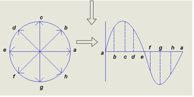
- The sinusoidal varying alternating quantity can be represented graphically by a straight line and arrow in the phase’s representation method.
- The length of the line represents magnitude and arrow indicates it direction.
- “The phases are assumed to be rotated in anticlockwise direction with constant Angular speed.”
- One complete cycle of sine wave is represented by one complete rotation of phases as shown below
|
Consider at various position
- At point A the y axis projection is zero
 θ=0
θ=0 
2. At point b the y axis projection 0b sin θ

3. At point c the y axis projection (0C) represent max value of phase


4. Point D, y axis projection is (0ɖ)

5. At point e, y axis projection is zero

Now at point “ȴ” on words the phases change its direction  cycle also shifts from the half cycle to –v e half cycle.
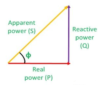
- Apparent power: (S):- it is defined as product of rms value of voltage (v) and current (I), or it is the total power/maximum power
S= V × I
Unit - Volte- Ampere (VA)
In kilo – KVA
2. Real power/ True power/Active power/Useful power: (P) it is defined as the product of rms value of voltage and current and the active component or it is the average or actual power consumed by the resistive path (R) in the given combinational circuit.
It is measured in watts
P = VI  Φ watts / KW, where Φ is the power factor angle.
3. Reactive power/Imaginary/useless power [Q]
It is defined as the product of voltage, current and sine B and I
Therefore,
Q= V.I  Φ
Φ
Unit –VA R
In kilo- KVAR
|
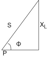
As we know power factor is cosine of angle between voltage and current
i.e. Φ.F= CosΦ
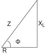
In other words, also we can derive it from impedance triangle
Now consider Impedance triangle in R.L.C circuit.
|
From triangle ,
Now  Φ – power factor=
Power factor =  Φ or
Φ or 
Resonance with Definition, condition and derivation
Resonance in series RLC circuit
Definition:
It is defined as the phenomenon which takes place in the series or parallel R-L-C circuit which leads to unity power factor
Voltage and current in R-L-C circuit are in phase with each other.
Resonance is used in many communication circuits such as radio receiver.
Resonance in series RLC -> series resonance in parallel->anti resonance/parallel resonance
Condition for resonance
XL=XC
Resonant frequency (fr): For given values R-L-C the inductive reactance XL becomes exactly equal to the capacitive reactance XC only at one particular frequency. This frequency is called as resonant frequency and denoted by ( fr)
Expression for resonant frequency (fr)
We know that
XL =  - inductive reactance
 capacitive reactance
At a particle or frequency f=fr,the inductive and capacitive reactance are exactly equal
Therefore, XL = XC ----at f=fr
i.e. 
Therefore, 

and rad/sec
Electrical Energy
Electrical energy is energy derived from electric potential energy or kinetic energy. When used loosely, electrical energy refers to energy that has been converted from electric potential energy. This energy is supplied by the combination of electric current and electric potential that is delivered by an electrical circuit (e.g., provided by an electric power utility).
At the point that this electric potential energy has been converted to another type of energy, it ceases to be electric potential energy. Thus, all electrical energy is potential energy before it is delivered to the end-use. Once converted from potential energy, electrical energy can always be called another type of energy (heat, light, motion, etc.).
Electrical energy is usually sold by the kilowatt hour (1 kW·h = 3.6 MJ) which is the product of the power in kilowatts multiplied by running time in hours. Electric utilities measure energy using an electricity meter, which keeps a running total of the electric energy delivered to a customer.
Power factor
The power factor is defined as the ratio of the active power (P) and volt-amperes. The active power is the real power which is assumed in an AC circuit, whereas volt-amperes are the apparent power which is produced in the circuit when the waves of voltage or current are not in phase.
|
Power factor =P/S=P/VI
For sinusoidal waveforms, the power factor is the cosine of the angle (phase angle) between voltage and current.
Power factor=cos∅
cos∅=P/VI
I=P/VCOS∅ .............Equation (1)
Equation (1) shows that the current is affected by the power factor. Hence, power P is load, the current I, taken from the load varie inversely as the load power factor cos∅. Thus a given load takes more current at a low power factor than it does at a high power factor.
Causes of low power factor:
The usual reason for the low power factor is because of the inductive load. The current in the inductive load lag behind the voltage. The power factor is therefore lagging. The important inductive loads responsible for the low power factor are the three-phase induction motors (which operate at a 0.8 lagging power factor), transformer, lamps and welding equipment operate at low lagging power factors. Power factor improvement methods are used for improving the value of power factor in a power system.
Disadvantage of low power factor:
The undesirable effect of operating a low load at a low power factor is due to the large current required for a low power factor. The important disadvantages of low power factor are:
- Higher current is required by the equipment, due to which the economic cost of the equipment is increased.
- At low power factor, the current is high which gives rise to high copper losses in the system and therefore the efficiency of the system is reduced.
- Higher current produced a large voltage drop in the apparatus. This results in the poor voltage regulation.
- Since both the capital and running cost are increased, the operation of the system at low power factor (whether it is lagging or leading) is uneconomical from the supplier’s point of view.
As we have already seen in the basics of power factor in electrical distribution system, most Industrial loads require both Real power and Reactive power to produce useful work.
Typically, inductive loads (motors, transformers etc) require two kinds of power to operate:
(1) Active Power (KW) – This actually performs the useful work
(2) Reactive Power (KVAR) – This helps to maintain the electromagnetic field.
The vector sum of the active power and the reactive power gives total power often required to the apparent power in a
KVA=KW+KVA
Low power factor in an electrical system often occur when inductive loads are operated below their full load capacity especially motors. Consistently operating electrical loads at low power factor will result in higher utility bills because of the poor utilization of electrical energy.
In fact, a higher power factor means less KVA and KVAR components and a more efficient utilization of electrical energy while a low power factor implies the presence of more KVA and reactive (KVAR) power components and less efficient electrical energy utilization.
Power Factor Formula:
We have already defined power factor in the basics of power factor in electrical distribution system. Here is the formula anyway:
P.F=KW/KVA
- Improving Power Factor with Capacitors:
The reactive component (KVAR) of any electrical distribution system can easily be reduced in order to improve power factor by using capacitors. Capacitors are basically reactive loads. They tend to generate reactive power. Hence, they find to use in power factor correction application.
The power factor of 0.7 and KVA requirement for the load is at 142KVA while the reactive power required is 100KVAR. On installing power factor improvement capacitors, power factor improved to 0.95.
The KVA requirement drops to 105KVA while the reactive power required is 33 KVAR, the balance of 67KVAR is now being supplied by the capacitor with significant impact on utility bills.
Benefits of Improving Power Factor with Capacitors:
When capacitors are used to improve power factor, the following benefits will accrue:
1. Reduced electrical power bills
2. Reduces I2R losses in electrical conductors
3. Reduces loading on transformers by releasing system capacity
4. Improves voltage on the electrical distribution system thereby allowing motors to run more efficiently and cooler. This helps to prolong the operation and life to the motor.
References:
1. V. Del Toro “ Principles of Electrical Engineering”, Prentice Hall
2. I.J. Nagrath “ Basic Electrical Engineering”, Tata McGraw Hill
3. D.F. Fitzgerald, A. Grabel Higginbotham “ Basic Electrical Engineering”, McGraw Hill
4. Mittal & Mittal “ Basic Electrical Engineering”, Tata McGraw Hill
5. B.L. Theraja and A.K. Theraja“A Text Book of Electrical Technology”, Volume - I & II
6. J. Millman & Halkias “ Electronic Devices & Circuits”, Tata McGraw Hill
7. Herbert Taub “ Digital Circuits & Microprocessors”, McGraw Hill
