1) Analysis of pin jointed simple and cantilever frames by method of joints and method of section
The analysis of pin joined is explained below
Truss: -
A Rigid structure formed by connecting various two force members to each other by using pin joint.
Plane truss:
When all members of the truss lie in one plane, then truss is known as plane truss
Rigid truss: -
A truss which do not collapse when external Load is applied on it.
Simple truss: -
The structure formed by basic triangle made by connecting various members are called simple truss
Classification of Truss: -
Perfect truss Imperfect (unstable)
(Stable) (n  2j R)
2j R)
(n=2j- R) over stable Deficient
Truss
(Redundant)
(n< 2 j – R) (n < 2 j-R)
- Perfect truss:
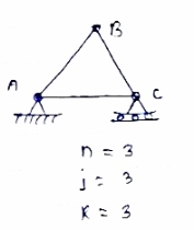
A truss which does not collapse under the action of Load is called perfect truss. Condition: n = 2 j-R
|
n= no. of member
j = no of joints
R = no. of reaction
In truss ABC, n = 3 & 2 j- R+3
So it is perfect truss
- Imperfect truss:
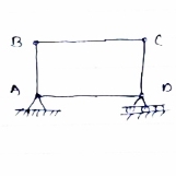
A truss which does not collapse under the load is called Imperfect or unstable truss.
Here n 2j -R
2j -R
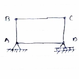
Over stable (Redundant Truss)
A truss in which n > 2j- R,
Then it is over stable truss.
Diagram
|
Deficient truss
It is a truss in which
N <2 j-R.
|
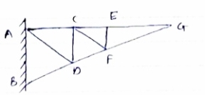
- Cantilever Truss:
A truss which is fixed on one side & free of other end is called as cantilever truss.
|
Assumption made in the analysis: -
1) Given truss a perfect truss
2) The truss member is connected by joints only.
3) External loads are acting at the joints only.
4) All members are two force members.
5) The self- weight of members is neglected.
|
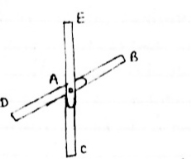
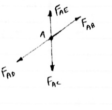
1) If when four members are connected At Engile joint in such a way That opposite members lie in a Single straight line
|
There is No external load acting at the joint Then Forces in the opposite members Are equal.
FAE = FAC & FAB = FAD.
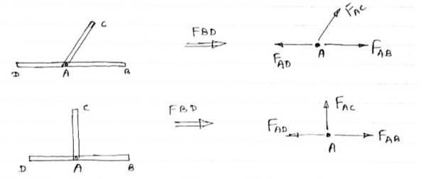
2) If there are only there members at a joint and Out of there, two are collinear and is inclined to first two or lar to first members, With no external load at joint,
|
Then,
a) Forces in the two opposite ( co- linear) members
Are equal. l.e FAD = FAB
b) The force in the inclined member is zero
l.e FAC =0
c) Force in the perpendicular member is zero
FAc = 0
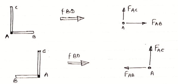
4) If there are two member at a joint with one Member Horizontal & one vertical, & there is no external load of joint.
|
Then, both members are zero force members,
Angle FAB=0
FAC =0
5) If there are only two members at joint With- one-member vertical & other inclined & there is no external load of joint,
|
Then both members are zero force members
i.e. FAB = 0 & FAC =0
One-member Horizontal & other inclined and there is No external load at joint.
|
Then both members are zero force members
FAB = 0 and FAC =0
6) if there are only two members at a joint with one member Horizontal & other inclined and there is no External load at joint
Diagram
|
Then both members are zero force member
FAB=0 and FAC = 0
Numerical; -
Analysis of Truss by method of joint method
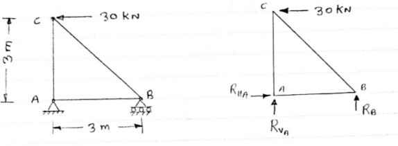
1) Determine the forces in all members of truss by joint method
|
Consider FAB of Truss, Applying conditions of equilibrium,
 = 0
= 0
RHA + 30 Kn
 = 0
= 0
RvA + RB =0
Taking moment at point A, = 0
= 0
-(RB* 3) - (30*3) = 0
RB = -30 KN
RB =30 KN RVA = 30 KN
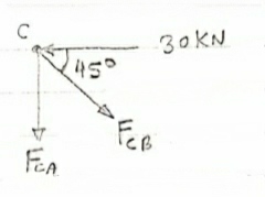
Consider Joint c, assuming forces in member AC & BC to be
Tensile, applying conditions of equilibrium,
|
 = 0
= 0
-30 + FCB cos 45 =0
FCB =30/cos 45 = 42.42 KN (T)
-  = 0
= 0
- FcA – FCB sin 45=o
-F CA -42.42 sin 45 =0
|
-FCA – 30= 0
-FCA = -30 KN
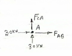
Consider Joint c, assuming forces in member AC & BC to be
Tensile, applying conditions of equilibrium,
 Fx = 0 30+FAB =0
FAB = -30KN
- Laws of coulomb frictions:
Coulomb (1736-1806) determined that the frictional force Friction between two bodies which are pressed together with a normal force FN exhibit the following simple properties in a rough approximation:
A. Static Friction. In order to set in motion a body lying on an even surface in a
State of rest, a critical force, the force of static friction Fs, must be overcome. This
Force is roughly proportional to the normal force FN 1:
Fs = μs N F.
The coefficient μs is called the coefficient of static friction. It is dependent on the
Pairing of the contacting materials, however, shows almost no dependence on contact area or roughness.
B. Kinetic Friction FR is the resisting force which acts on a body after the Force of static friction has been overcome. Coulomb experimentally determined the following properties of kinetic friction:
Kinetic friction is proportional to the normal force FN:
FR = μk N F
It shows no considerable dependence on the contact area or roughness of the
Surface.
The coefficient of kinetic friction is approximately equal to the coefficient of
Static friction:
μk s ≈ μ
This proportionality is known as Amontons’ law.
1) Frictional force always acts in opposite direction in which body tends to move
2) Frictional force is directly proportional to normal reaction
3) Frictional force is equal to net force acting in the direction in which object tends to move.
4) Frictional force does not depend on the surface area contacts.
5) Frictional force depends upon roughness of surface.
2. Problems involving dry friction:
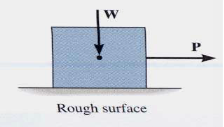
Friction is defined as a force of resistance acting on a body which prevents or retards slipping of the body relative to a second body. Experiments show that frictional forces act tangent (parallel) to the contacting surface in a direction opposing the relative motion or tendency for motion.
For the body shown in the figure to be in equilibrium, the following must be true:
F = P, N = W, and Wx = Ph
.
|
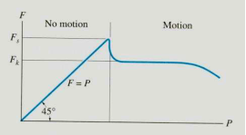
To study the characteristics of the friction force F, let us assume that tipping does not occur (i.e., “h” is small or “a” is large). Then we gradually increase the magnitude of the force P. Typically, experiments show that the friction force F varies with P, as shown in the right figure above.
The maximum friction force is attained just before the block begins to move (a situation that is called “impending motion”). The value of the force is found using Fs =s N, where s is called the coefficient of static friction. The value of s depends on the materials in contact. Once the block begins to move, the frictional force typically drops and is given by Fk = k N. The value of k (coefficient of kinetic friction) is less than s.
Steps for solving equilibrium problems involving dry friction:
1. Draw the necessary free body diagrams. Make sure that you show the friction force in the correct direction (it always opposes the motion or impending motion).
2. Determine the number of unknowns. Do not assume F =sN unless the impending motion condition is given.
3. Apply the equations of equilibrium and appropriate frictional equations to solve for the unknowns.
3. Simple application like wedges:
Wedges are a useful engineering tool, and the approach used for wedges also finds its way into other engineering applications.
A good rule to stick to is that when a wedge is in use, the forces on the faces will both be in the same direction. That is either towards, or away from the point of the wedge.
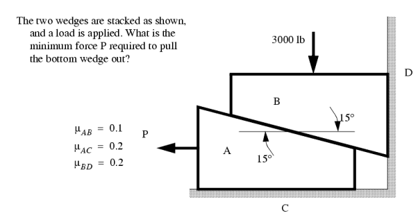
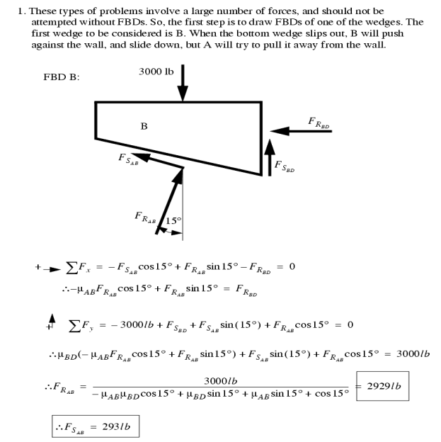
When solving friction problems we look for friction that is about to let go and start slipping. Keep in mind that not all surfaces will slip, this should be verified after the solution. For all surfaces that slip the friction force will be at the maximum value. The example below shows how to deal with a multiple wedge problem.
|
4. Belt friction and band brakes
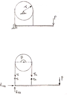
- Belt friction:
- Flat Belt:
|
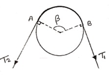
Let,
T1 Tension in Tight side of belt
T2 Tension in Slack side of belt
 = Lap angle or angle of contact in radians
 S = coefficient. Of static friction
 K = coefficient. Of kinetic friction
When belt is about to slip:
 =
=  ……… (T1 > T2)
 (in motion) :
 =
=  ……… (T1 > T2)
2. V-Belt
 =
= 
Where  = abgle of V groove or belt
3. Band – Brake :
|
Simple Band Brake:
Friction can be used as a power-transmitting agent (in belts-pulleys) as well as a power-absorbing agent (in band brakes). The idea is, the band resists the motion of rotating wheel through friction. The braking torque is obtained by the relations
And
|
In this case, the values of  and
and  depend on the applied force
  as well. Drawing the free body diagram of lever and pulley is necessary.
1. Differential wheel and axle
Differential axle and wheel is a further modification and improvement over the simple axle and wheel.
It consists of a load axle made up of bigger axle of diameter d1 and smaller axle of diameter d2 rigidly connected to each other and an effort wheel of diameter „D‟. Since, the load axle is made up of two axles of different diameters; it is called as a differential axle. Differential axle and effort wheel are mounted on the same shaft which is supported on ball bearings as shown in the figure.
A string is wound round the effort wheel so as to apply the effort „P‟. Another string is wound round the bigger axle further passing over the pulley carrying the load „W‟ attached to the snatch block. The same string is further wound round the smaller axle in the opposite direction to that of bigger axle. The winding of string on effort wheel and smaller axle is done in the same direction; the string unwinds from the effort wheel & smaller axle and winds over the bigger axle simultaneously, when the effort „P‟ is applied.
When effort wheel complete one revolution, the differential axle also completes one revolution.
Distance travelled by the effort = πD
Length of the string wound over the bigger axle = πd1
Length of the string unwound over the smaller axle = πd2
Total winding over the bigger axle = πd1 - πd2 = π(d1 – d2)
But, the load „W‟ is lifted through half of the total winding because snatch block with a movable pulley supports the load
Distance travel by the load = ½ (total winding) = ½ π(d1-d2) = π/2(d1-d2)
We know that
V.R. = Distance travelled by the effort / Distance travelled by the load
= Πd / (π/2) x (d1-d2)
Where, D = Diameter of effort wheel, d1 = diameter of bigger axle, d2 = diameter of smaller axle.
If radius of effort wheel, bigger axle and smaller axle are given then,
V.R = 2R / R1- R2
Where, R = Diameter of effort wheel, R1 = diameter of bigger axle, R2 = diameter of smaller axle.
2. Single and double purchase crab:
Single purchase crab:
This machine consists of mainly the larger gear wheel known as Spur or main gear and smaller gear known as pinion. Spur or main gear is mounted rigidly on the load drum or load axle and the spur is geared to the pinion which is further mounted rigidly on the shaft to which the effort wheel or handle is attached.
A rope or string is wound round the load drum so as to lift the load W‟ and another string is wound round the wheel so as to apply the Effort „P‟ as shown in the figure. Let, W = Load lifted, P = Effort applied, D = diameter of effort Wheel, T1 = number of teeth on spur or main gear, T2 =number of teeth on pinion d = diameter of load drum or load axle.
For one complete revolution of effort wheel, distance moved by the effort = πD and the pinion also completes one revolution, that time spur performs T2/T1 revolutions and as load drum and spur being rigidly connected, the load drum also performs T2/T1 revolutions.
- Distance moved by the load = T2/T1 x circumference of load drum
= T2/T1 x πd
We know that,
V.R. = Distance travelled by the effort / Distance travelled by the load
= Πd / (T2/T1) x πd
V.R = D/d x T2/T1
If handle of length „L‟ is used in place of effort wheel,
V.R = 2L/d x T2/T1
Where L =length of the handle.
Double Purchase Crab:
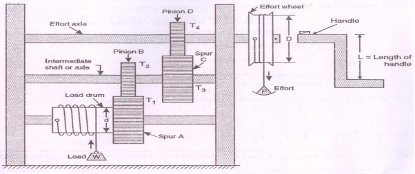
This machine consists of two larger gear wheels A and C called as spurs or main gears and smaller gear wheels B and D called as pinions as shown in the figure. A load drum or load axle is rigidly connected to the spur A, which is further geared with pinion B. Pinion B and spur C are rigidly mounted on same shaft called as intermediate shaft or axle and spur C is further geared with pinion D mounted on the shaft. So called as effort axle to which the effort wheel is attached.
Let, W = Load lifted, P = Effort applied, D = diameter of effort wheel, d = diameter of load drum or load axle.
T1 = number of teeth on spur A, T2 = number of teeth on pinion B mounted on intermediate shaft, T3 = number of teeth on spur C mounted on intermediate shaft,
T4 = number of teeth on pinion D mounted on effort axle
|
For one complete revolution of effort wheel,
Distance moved by effort = πD
The pinion D on the effort axle also makes one revolution and therefore spurs C and pinions B on the intermediate shaft performs revolution. T4/T3
That time, spur A and load drum performs same revolutions as T4/T3 X T2/ T1
Because both are rigidly connected to each other.
Distance moved by the load= T4/T3 X T2/ T1 revolutions x circumference of load drum
= T4/T3 X T2/ T1 x πd
We know that,
V.R. = Distance travelled by the effort / Distance travelled by the load
= ΠD / (T4/T3 X T2/T1) x πd
= D/d x T1/T2 x T3/T4
If handle of length „L‟ is used in place of effort wheel, where, L =length of the handle.
V.R = 2L /d x T1/T2 x T3/T4
3. Velocity ratio:
It is defined as the ration of distance travelled by the effort (P) to the distance travelled by the load (W)
V.R. = Distance travelled by the effort / Distance travelled by the load
Velocity ratio will be always more than one and for a given machine, it remains constant.
4. Mechanical Advantage:
It is defined as the ratio of load to be lifted to the effort applied.
M.A = Load(w) /Efforts(p)
5. Efficiency:
If a machine overcomes a load ‘L’ and the distance travelled by the load is ‘Ld’, the work done by the load is L × Ld. It is also called output work or useful work. Therefore,
Output work = L × Ld
Likewise, the effort applied to overcome the load is E and the distance covered by effort is Ed, the work done by effort is E × Ed. It is also called input work. Therefore,
Input work = E × Ed
The efficiency of a simple machine is defined as the ratio of useful work done by a machine (output work) to the total work put into the machine (input work).
For ideal or perfect machine, work output is equal to the work input. Ideal machines are those imaginary machines which are frictionless. In practice, the work output of a machine is always less than work input due to the effect of friction. If the frictional force in the machine increases the efficiency decreases because machines are frictionless in practice, the efficiency of a machine can never be 100%
References:
1. Engineering Mechanics: F. L. Singer
2. Engineering Mechanics: Timoshenko & Young
3. Engineering Mechanics: Bear & Johnston
4. Engineering Mechanics: I. H. Shames
5. Engineering Mechanics: A. Nelson
