Magnetic Circuit &Single Phase Transformer
A magnetic circuit is made up of one or more closed loop paths containing a magnetic flux. The flux is usually generated by permanent magnets or electromagnets and confined to the path by magnetic cores consisting of ferromagnetic materials like iron, although there may be air gaps or other materials in the path. Magnetic circuits are employed to efficiently channel magnetic fields in many devices such as electric motors, generators, transformers, relays, lifting electromagnets, SQUIDs, galvanometers, and magnetic recording heads
Some examples of magnetic circuits are:
- Horseshoe magnet with iron keeper (low-reluctance circuit)
- Horseshoe magnet with no keeper (high-reluctance circuit)
- Electric motor (variable-reluctance circuit)
- Some types of pickup cartridge (variable-reluctance circuits)
Magneto motive force (MMF)
Similar to the way that electromotive force (EMF) drives a current of electrical charge in electrical circuits, magneto motive force (MMF) 'drives' magnetic flux through magnetic circuits. The term 'magneto motive force', though, is a misnomer since it is not a force nor is anything moving. It is perhaps better to call it simply MMF. In analogy to the definition of EMF, the magneto motive force around a closed loop is defined as:
F=∫ H.dl
Magnetic flux
An applied MMF 'drives' magnetic flux through the magnetic components of to the number of magnetic field lines that pass through the cross sectional area of that component. This is the net number, i.e. the number passing through in one direction, minus the number passing through in the other direction. The direction of the magnetic field vector B is by definition from the south to the North Pole of a magnet inside the magnet; outside the field lines go from north to south. The system. The magnetic flux through a magnetic component is proportional
The flux through an element of area perpendicular to the direction of magnetic field is given by the product of the magnetic field and the area element. More generally, magnetic flux Φ is defined by a scalar product of the magnetic field and the area element vector. Quantitatively, the magnetic flux through a surface S is defined as the integral of the magnetic field over the area of the surface.
∅m=∫∫sB.dS
For a magnetic component the area S used to calculate the magnetic flux Φ is usually chosen to be the cross-sectional area of the component. The SI unit of magnetic flux is the weber (in derived units: volt-seconds), and the unit of magnetic flux density (or "magnetic induction", B) is the weber per square meter, or tesla.
Circuit model
The most common way of representing a magnetic circuit is the resistance–reluctance model, which draws an analogy between electrical and magnetic circuits. This model is good for systems that contain only magnetic components, but for modelling a system that contains both electrical and magnetic parts it has serious drawbacks. It does not properly model power and energy flow between the electrical and magnetic domains. This is because electrical resistance will dissipate energy whereas magnetic reluctance stores it and returns it later. An alternative model that correctly.
As the path of an electric current is known as an electric circuit, similarly the path of magnetic flux is known as magnetic circuit.
As an electric e.m.f. is necessary to cause the flow of current in an electric circuit, similarly magneto-motive force is required to create the magnetic flux in the magnetic circuit.
As the current flowing in an electric circuit depends upon the e.m.f. and resistance of the circuit, similarly the magnetic flux or number of lines of force produced in any magnetic circuit depends upon the magneto-motive force acting in the circuit and reactance of the circuit.
Let us consider a solenoid of length l metres, turns N, cross-sectional area, a metres2 and carrying a current of 'I' amperes.
Field strength inside the solenoid, H = NI metre.
If the solenoid is wound on magnetic substance of relative permeability μr then
Flux density B=𝛍OμrH=NIμoμr
Magnetic circuit with DC excitation
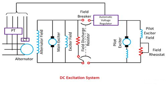
The DC excitation system has two exciters – the main exciter and a pilot exciter. The exciter output is adjusted by an automatic voltage regulator (AVR) for controlling the output terminal voltage of the alternator. The current transformer input to the AVR ensures limiting of the alternator current during a fault.
When the field breaker is open, the field discharge resistor is connected across the field winding so as to dissipate the stored energy in the field winding which is highly inductive.
|
The main and the pilot exciters can be driven either by the main shaft or separately driven by the motor. Direct driven exciters are usually preferred as these preserve the unit system of operation, and the excitation is not excited by external disturbances.
The voltage rating of the main exciter is about 400 V, and its capacity is about 0.5% of the capacity of the alternator. Troubles in the exciters of turbo alternator are quite frequent because of their high speed and as such separate motor driven exciters are provided as standby exciter.
Magnetic circuit AC excitation
The AC excitation system consists of an alternator and thyristor rectifier bridge directly connected to the main alternator shaft. The main exciter may either be self-excited or separately excited. The AC excitation system may be broadly classified into two categories which are explained below in details.
Rotating Thyristor Excitation System
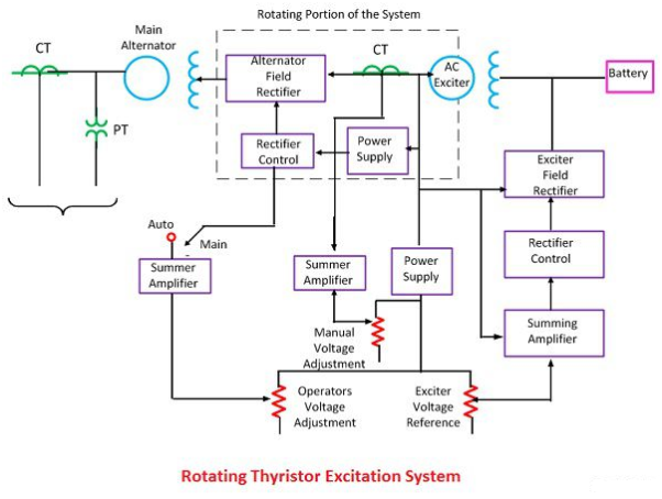
The rotor excitation system is shown in the figure below. The rotating portion is being enclosed by the dashed line. This system consists of AC exciter, stationary field and a rotating armature. The output of the exciter is rectified by a full wave thyristor bridge rectifier circuit and is supplied to the main alternator field winding.
|
The alternator field winding is also supplied through another rectifier circuit. The exciter voltage can be built up by using it residual flux. The power supply and rectifier control generate the controlled triggering signal. The alternator voltage signal is averaged and compare directly with the operator voltage adjustment in the auto mode of operation. In the manual mode of operation, the excitation current of the alternator is compared with a separate manual voltage adjustment.
Brushless Excitation System
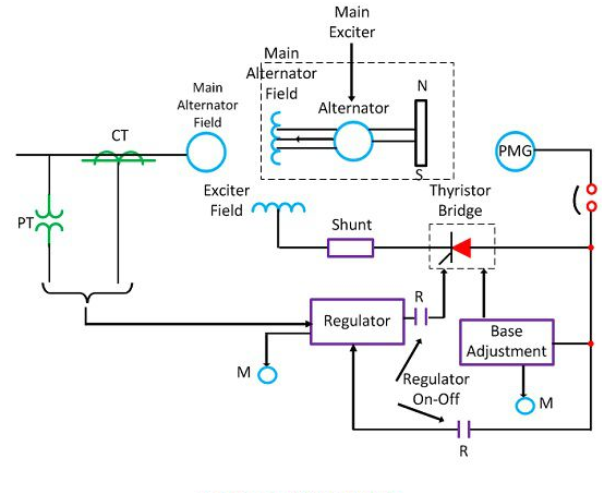
This system is shown in the figure below. The rotating portion is enclosed by a dashed line rectangle. The brushless excitation system consists of an alternator, rectifier, main exciter and a permanent magnet generator alternator. The main and the pilot exciter are driven by the main shaft. The main exciter has a stationary field and a rotating armature directly connected, through the silicon rectifiers to the field of the main alternators.
|
The pilot exciter is the shaft driven permanent magnet generator having rotating permanent magnets attached to the shaft and a three phase stationary armature, which feeds the main exciter field through silicon rectifiers, in the field of the main alternator. The pilot exciter is a shaft driven permanent magnetic generator having rotating permanent magnets attached to the shaft and a 3-phase stationary armature, which feeds the main’s exciter through 3-phase full wave phase controlled thyristor bridges.
The system eliminates the use of a commutator; collector and brushes have a short time constant and a response time of fewer than 0.1 seconds. The short time constant has the advantage in improved small signal dynamic performance and facilitates the application of supplementary power system stabilising signals.
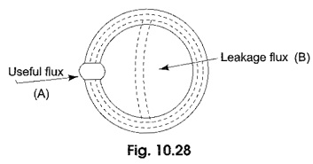
Magnetic Leakage and Fringing – Figure 10.28 shows a magnetized iron ring with a narrow air gap and the flux which crosses the gap can be regarded as useful flux. Some of the total flux produced by the ring does not cross the air gap, but instead takes a shorter route as shown in Fig. 10.28 and is known as leakage flux.
|
The flux while crossing the air gap bulges outwards due to variation in reluctance. This is known as fringing. This is because the lines of force repel each other when passing through the air as a result the flux density in the air gap decreases. For the purpose of calculation, it is assumed that the iron carries the whole of the total flux throughout its length.
The ratio of total flux to useful flux is called the leakage coefficient or leakage factor.
Leakage factor=Total flux/useful flux
|
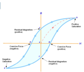
- When tested experimentally, a ferromagnetic material such as iron will produce a curve similar to that shown above.
- First there is an upper/lower limit to the magnetic flux density which may be achieved, which occurs at positive or negative saturation, respectively. This is related to the crystalline structure of the iron, where each crystal has its own – initially random – magnetic orientation.
- Increasing the magnetic field strength in either direction causes more and more magnetic 'domains' to align with the external magnetic field, but once almost all of the domains have aligned themselves, then little further increase in magnetic flux density is possible. The ferromagnetic material is said to be saturated.
- The curve demonstrates magnetic hysteresis or 'lag' as the sample is alternatively magnetized in the positive and negative directions. When initially magnetized, the curve follows point’s a–b on the graph, but on reducing H to zero, some residual magnetism remains (point c - also known as the remnant flux density).
- In order to fully demagnetize the specimen, it is necessary to apply a negative magnetic field strength (point d - called the coercive force). Making H increasingly negative leads to negative saturation (point e). If H is reduced back to zero, point f is reached (negative residual magnetism). As H becomes positive, the flux density reduces to zero (point g) and then becomes positive.
- Finally returning back to point b (positive saturation), after which the cycle b–g repeats. The area enclosed by the B-H curve (shaded light blue above) is proportional to the energy loss as the ferromagnetic material is magnetized with varying polarity by connection to an alternating (AC) power supply.
- This energy loss is undesirable and causes unwanted heating of the material. In general, harder ferromagnetic materials have higher hysteresis losses, since more energy is required to realign the magnetic domains. Steel, to which a small proportion of silicon has been added, is commonly used for applications such as transformer cores and motor rotors, due to its lower hysteresis loss.
- For smaller applications, such as inductor cores, passive filters, miniature transformers and antennas, then ferrite (a ceramic-like combination of metallic oxides including ferric oxide) is a popular choice.
In a ferromagnetic material, not of all the energy of the magnetic field is returned to the circuit, when the mmf is removed, hysteresis loss is seen. The energy expended in taking a specimen through a magnetic cycle is also known as hysteresis loss. Hysteresis loss per cubic metre per cycle of magnetization of a magnetic material depends upon
- the maximum value of flux density and
- The magnetic quality of the material.
Determination of Hysteresis loss:
|
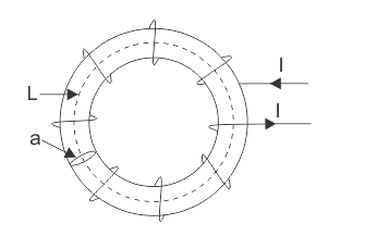
Consider a ring of specimen circumference l meters, cross sectional area a meter square and having N turns of an insulated wire. Let the current flowing through the coil be of I amperes.
Magnetizing force,
H=NI/L OR I=HL/N
B=flux density at this instant.
Φ=total flux through the ring=Ba webers.
The flux produces in the iron ring alters as the current flowing through the solenoid alters.Hence the emf is induced and given by,
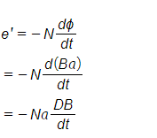
According to the Lenz’s law, this induced emf will oppose the flow of current .so therefore to maintain the current I in the coil the source of supply must have an equal and opposite emf.
Hence applied emf,

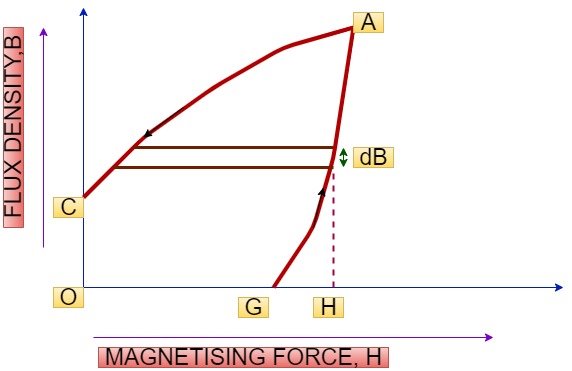
Energy consumed in short time dt, during which flux density has changed,
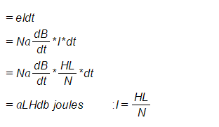
Thus the total work done or energy consumed during one complete cycle of magnetization,

Now, aL=volume of the ring.
HdB = area of elementary strip of B-H curve.
∫HdB=the total area enclosed by hysteresis loop
|
Minimization of Hysteresis loss
Hysteresis loss can be minimized by choosing a core material with low hysteresis coefficient such as low carbon steel, silicon alloys, and alloy steel.
Eddy current losses
voltage induced in the core material (conducting material) by the alternating flux causes circulating currents known as eddy currents. Eddy currents are associated with I^2R loss called eddy current loss. The eddy current loss depends upon:
- The maximum value of flux density.
- Number of complete magnetization cycles per second.
- Thickness of the lamination.
- Volume of the core material.
Eddy current loss is given by,
Pe=ke (Bmax)2 f 2t2v watts
Where,
Ke = eddy current coefficient and depends upon the type of magnetic material used.
f=number of complete magnetization cycles per second.
Bmax=maximum flux density in teslas (Wb/m^2)
t=thickness of lamination in metres.
v=volume of core material in m^3.
Minimization of eddy current losses
To increase the core resistance and to minimize eddy currents magnetic cores subjected to alternating fluxes are assembled from thin sheets with an insulating layer between successive lamination. Hence the eddy currents loss can be minimized by using thin lamination.
Application of Eddy current:
- Eddy current heating.
- Eddy current breaking.
- Develop damping torque in measuring instruments.
Parallel Magnetic Circuit:
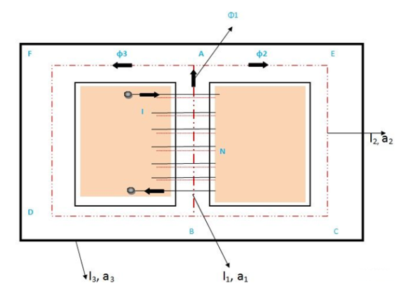
A magnetic circuit having two or more than two paths for the magnetic flux is called a parallel magnetic circuit. Its behaviour can be compared to the parallel electric circuit. The parallel magnetic circuit contains different dimensional areas and materials having various numbers of paths.
|
The above figure shows a parallel magnetic circuit. In this circuit, a current-carrying coil is wound on the central limb AB. This coil sets up the magnetic flux φ1 in the central limb of the circuit. The flux φ1 which is in the upward direction is further divided into two paths namely ADCB and AFEB. The path ADCB carries flux φ2, and the path AFEB carries flux φ3. It is clearly seen from the above circuit that
Φ1=φ2+φ3
The two magnetic paths ADCB and AFEB form the parallel magnetic circuit, thus, the ampere-turns (ATs) required for this parallel circuit are equal to the ampere-turns (ATs) required for any one of the paths.
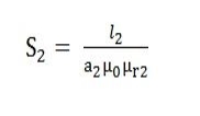
As we know, reluctance is If S1 = reluctance of path BA will be S2 =reluctance of path ADCB will be S3 = reluctance of the path AFEB will be |
Therefore, the total MMF or the total Ampere turns required in the parallel magnetic circuit will be the sum of all the individual parallel paths.
Total mmf required = mmf required for the path BA +mmf required for the path ADCB + mmf required for the path AFEB
φ1, φ2, φ3 stands for flux and S1, S2, S3 are the reluctances of the parallel path BA, ADCB and AFEB respectively. |
Series magnetic circuit
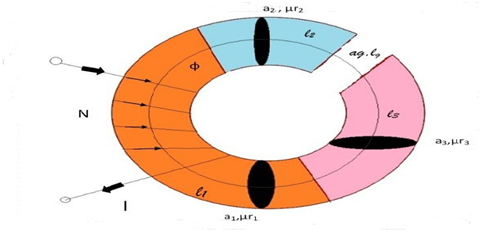
The Series Magnetic Circuit is defined as the magnetic circuit having a number of parts of different dimensions and materials carrying the same magnetic field. Consider a circular coil or solenoid having different dimensions as shown in the figure below:
|
Current ‘I’ is passed through the solenoid having N number of turns wound on the one section of the circular coil. Φ is the flux, set up in the core of the coil. a1, a2, a3 are the cross-sectional area of the solenoid. l1, l2, l3 are the length of the three different coils having different dimension joined together in series.
µr1, µr2, µr3 are the relative permeability of the material of the circular coil.
ag and are the area and the length of the air gap.
The total reluctance (S) of the magnetic circuit is
|
Total MMF = φ x S.......(1)
Substitue the S value in above Equation, we get
|
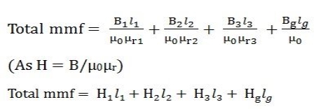
As (B = φ/a) putting the valve of B in the equation (2) we obtain the following equation for the total MMF
|
B-H Curve:
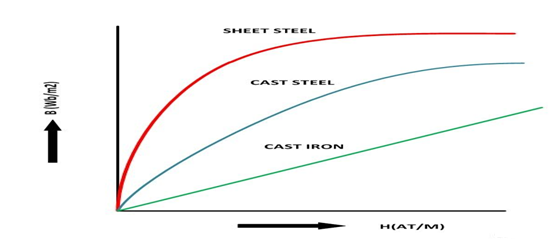
The graph plotted between the flux density (B) and the magnetising force (H) of any material is called B-H Curve or the magnetisation curve.
The shape of the B-H curve is mostly non-linear this means that the relative permeability (µr) of the material varies and is not constant. The value of relative permeability mainly depends on the value of flux density.
But for the non-magnetic materials like plastic, rubber, etc. and for the magnetic circuit having an air gap, its value is constant, denoted by (µ0). Its value is 4πx10-7 H/m and commonly known as absolute permeability or permeability of free space.
|
B-H curve for the various materials like cast iron, cast steel and sheet steel is shown in the above figure.
Coupling
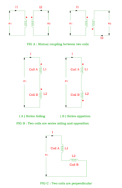
When two coils (or more than two coils) are connected by common magnetic flux, they are called as coupled with each other.
Mutual Coupling:
The circuit element used to represent magnetic coupling is known as Mutual coupling.
It is donated by symbol M and its unit is Henry.
The induced emf in the second coil due to current flows through one coil is related by
e2 = M di1 / dt
The dot sign indicates direction of current in the coil.
If the current flows through both coil A and coil B, the induced emf in the two coils A and coil B is
e1 = L1 (di1 / dt) + M (di2 / dt)
e2 = L2 (di2 / dt) + M (di1 / dt)
|
The operation of electric motors is governed by various laws of electricity and magnetism, including Faraday’s law of induction, Ampère’s circuital law, Lenz’ law and the Lorentz force. The first two – Faraday’s law and Ampère’s circuital law – are included in Maxwell’s equations. Together with Lenz’ law and the Lorentz force, these principles form the basis of electromagnetism.
Faraday’s law of induction:
Faraday’s law generally states that in a closed coil (loop) of wire, a change in the magnetic environment of the coil causes a voltage, or emf (electromotive force), to be induced in the coil.
The change in magnetic environment can be caused by changing the magnetic field strength, moving the magnet toward or away from the coil, moving the coil into or out of the magnetic field, or rotating the coil in the field.
The induced emf equals the negative rate of change of the magnetic flux, times the number of turns in the coil:

Where:
E = emf (V)
N = number of turns in the coil
Φ = magnetic flux (weber, Wb)
t = time (s)
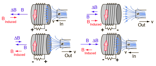
Lenz’ law:
A common way to state Lenz’ law is, “When emf is generated by a change in magnetic flux, the polarity of the induced emf is such that it generates a current whose magnetic field is in a direction that opposes the change that produced it (the original magnetic field).” That is, the induced magnetic field always works to keep the magnetic flux constant.
|
Lorentz force:
The Lorentz force is the force that a particle experiences due to electric and magnetic fields. Electric fields exert a force on a particle whether it is moving or not, while magnetic fields exert a force only when the particle is in motion. The combination of forces from electric and magnetic fields is given as:
F=q (E+vB)
Which Simplifies to
F=qE+qvB
Where:
F = force (N)
q = particle of charge
E = electric field (N/C)
v = velocity perpendicular to magnetic field (m/s)
B = magnetic field, (T)
Ampère’s circuital law:
A magnetic field exerts a force on a straight wire that is carrying current. With Ampère’s circuital law, the strength of the magnetic field can be determined by:

Where:
B = magnetic field (T)
μ0 = magnetic permeability of air, T-m/A
I = current (A)
r = distance from the wire (m)
When the wire is a loop, the magnetic field causes a force in one direction on one side of the loop, and in the opposite direction on the other side of the loop. This creates a torque, which causes the coil to spin. Note that if direct current is applied, the coil will oscillate back and forth, but will not make complete revolutions – this is the reason DC motors. Motors that are operated with alternating current (AC motors) don’t exhibit this problem.
|
- Types of transformers
Acc to input supply : I phase and  phase
phase
Acc to construction: core and shell type
Acc to 0/P: step up and step down
Construction of transformers (study only for MCQs)
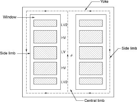
|
- Laminated steel core
Material used for core is (silicon steel) it is used for its (high permeability) and (low magnetic reluctance)
 magnetic field produced is very strong
The core is formed of (stacks of laminated thin steel sheets) which are electrically isolated from each other. They are typically (0.35 to 0.5 mm thick)
We can used 2 ‘L’ shaped sheets or 2  shaped sheets for laminations
Construction and types
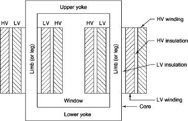
- There a 2 types of winding
- Concentric or cylindrical
- Sandwiched type
- Cylindrical
L.V. = low voltage H.V. = high voltage are mounted on same limb to minimum leakage.
|
L.V. Winding placed inside and H.V. winding placed outside with (proper insulation between the winding as it is easy to insulated L.V. winding) than H.V. winding.
2. Sandwiched
|
The H.V. and L.V. winding are divided into no. of small coils and their small windings are interleaved.
(The top and bottom winding are L.V. coils because they are close to core)
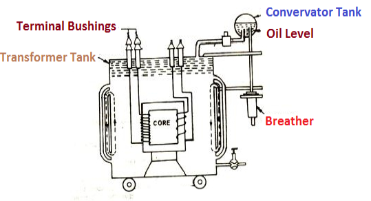
- Transformer tank: wholes assembly of winding and core placed inside the Transformer tank (sheet metal tank) which is filled with Transformer oil or insulating oil which acts as an (insulator or coolant) MCQ
- Transformer oil: (The function of oil is to remove efficiently the heat generated in core and in winding)
- Moisture should not be allowed which creeps the insulation which achieved by closed Transformer tank.
(To increase cooling surface are tubes or fins are provided)
- Conservator tank: Above tank T/F tank there is one small tank in which same empty space is always provided above the oil level. (this space is required for oil to expand or contract due to temperature change) MCQ
However, during contraction outside air can have moisture which will deteriorate the insulating properly of oil?
- Breather: the air goes in or out through the breather (To reduce the moisture content of their air. same drying agents such as (silica gel or) calcium chloride) is used in the breather (The dust particles present in air are also removed by breather)
- Buccholz Relay: (for incipient (slowly increasing) faults
There is pipe connecting rain tank and conservator. On the pipe a protective device called Buccholz Relay is mounted.
When the Transformer is about to be faulty and draw range current the oil becomes very hot and decompose.
During this process different types of gases are liberated. (The Bucchoz Relay gets operated by these gases) and gives an alarm to the operator. ɡȴ the fault continues to persist then there lay will trip off main circuit breaker to protect the Transformer.
- Explosion Vent:
An explosion Vent or relief value is the bent up pipe filled on the main tank.
(The explosion vent consist of aluminium of oil) when the T/F becomes faulty the cooling oil get decomposed and various types of gases are liberated
(ɡȴ the gas pressure exodus certain level then the aluminium of oil (diagram) in explosion vent will burst) to release pressure. This will save main tank from getting damaged.
- Single phase transformer - for MCQs
(Symbol and principal of operation)
It is a static device which can transfer electrical energy from one ac circuit to another ac circuit without change in frequency
It can increase or decrease the voltage but with corresponding decrease or increase in current
It works on Principle 
“Mutual Induction”
A major application of transformer is to increase voltage before transmitting electrical energy over a long distance through conductors and to again reduce voltage at place where it is to be used.
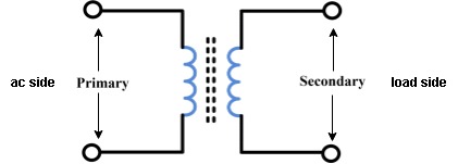
Symbol
|
- Primary winding: (ac supply side) For MCQs
The winding which is connected to supply is called primary side
2. Secondary winding: (load side) for MCQs
The winding which is connected to load is called as secondary winding
- Working: For MCQs
It works on principle of mutual Induction i.e. “when 2 coils are inductively coupled and if current in one coil is changed uniformly then an emf get induced in another coil”
- When alternating voltage V1 is applied to primary winding am alternating current I1 flows in it producing alternating flux in the core.
- As per Faradays Law of Electromagnetic Induction 1 an emf E1 is induced in the primary winding E = N1

- The emf induced in the primary winding is nearly equal and opposite to applied voltage V1
- Assuming leakage flux to be negligible almost whole flux produced in primary winding links with secondary winding thence emf induced in the secondary winding E2 = N2

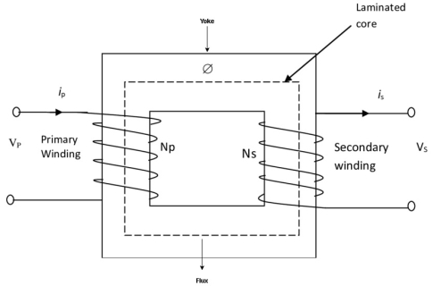
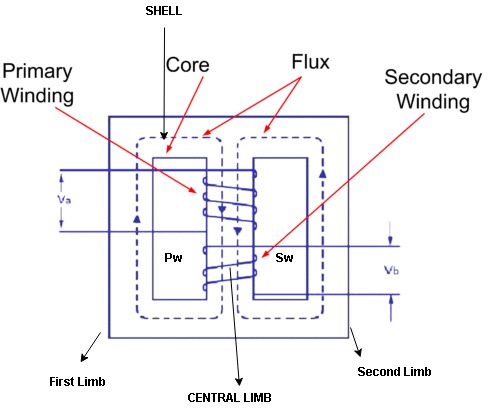
- Core and shall type transformers
Core Diagram
|
Shell Diagram:
|
Transformer on No Load Condition:
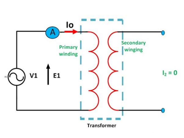
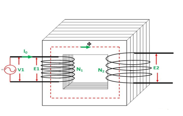
When the transformer is operating at no load, the secondary winding is open-circuited, which means there is no load on the secondary side of the transformer and, therefore, current in the secondary will be zero. While primary winding carries a small current I0 called no-load current which is 2 to 10% of the rated current.
This current is responsible for supplying the iron losses (hysteresis and eddy current losses) in the core and a very small amount of copper losses in the primary winding. The angle of lag depends upon the losses in the transformer. The power factor is very low and varies from 0.1 to 0.15.
|
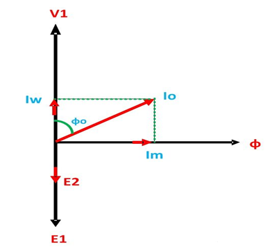
The no-load current consists of two components:
- Reactive or magnetizing component I: m
It is in quadrature with the applied voltage V1. It produces flux in the core and does not consume any power.
- Active or power component Iw, also known as a working component.
It is in phase with the applied voltage V1. It supplies the iron losses and a small amount of primary copper loss.
The following steps are given below to draw the phasor diagram:
- The function of the magnetizing component is to produce the magnetizing flux, and thus, it will be in phase with the flux.
- Induced emf in the primary and the secondary winding lags the flux ϕ by 90 degrees.
- The primary copper loss is neglected, and secondary current losses are zero as
I2 = 0.
Therefore, the current I0 lags behind the voltage vector V1 by an angle ϕ0 called the no-load power factor angle and are shown in the phasor diagram above. - The applied voltage V1 is drawn equal and opposite of the induced emf E1 because the difference between the two, at no load, is negligible.
- Active component Iw is drawn in phase with the applied voltage V1.
- The phasor sum of magnetizing current Im and the working current Iw gives the no-load current I0.
|
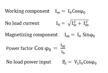
From the phasor diagram drawn above, the following conclusions are made
|
This is all about transformer in no-load condition.
Transformer on Load Condition:
When the transformer is on the loaded condition, the secondary of the transformer is connected to load. The load can be resistive, inductive or capacitive. The current I2 flows through the secondary winding of the transformer. The magnitude of the secondary current depends on the terminal voltage V2 and the load impedance. The phase angle between the secondary current and voltage depends on the nature of the load.
Operation of the Transformer on Load Condition:
The Operation of the Transformer on Load Condition is explained below:
When the secondary of the transformer is kept open, it draws the no-load current from the main supply. The no-load current induces the magneto motive force N0I0 and this force set up the flux Φ in the core of the transformer. The circuit of the transformer at no load condition is shown in the figure below
When the load is connected to the secondary of the transformer, I2 current flows through their secondary winding. The secondary current induces the magneto motive force N2I2 on the secondary winding of the transformer. This force set up the flux φ2 in the transformer core. The flux φ2 opposes the flux φ, according to Lenz’s law.
|
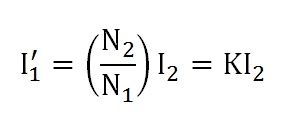
- As the flux φ2 opposes the flux φ, the resultant flux of the transformer decreases and this flux reduces the induced EMF E1. Thus, the strength of the V1 is more than E1 and an additional primary current I’1 drawn from the main supply.
The additional current is used for restoring the original value of the flux in the core of the transformer so that V1 = E1. The primary current “I’1” is in phase opposition with the secondary current I2. Thus, it is called the primary counter-balancing current. - The additional current I’1 induces the magneto motive force N1I’1. And this force set up the flux φ’1. The direction of the flux is the same as that of the φ and it cancels the flux φ2 which induces because of the MMF N2I2
|
Therefore,
- The phase difference between V1 and I1 gives the power factor angle ϕ1 of the primary side of the transformer.
- The power factor of the secondary side depends upon the type of load connected to the transformer.
- If the load is inductive as shown in the above phasor diagram, the power factor will be lagging, and if the load is capacitive, the power factor will be leading. The total primary current I1 is the vector sum of the currents I0 and I1’. i.e.
|
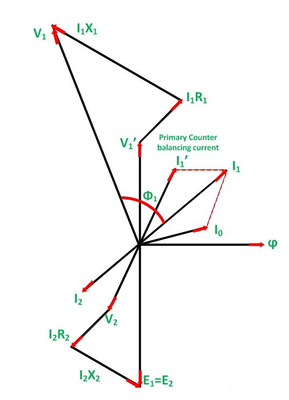
Phasor Diagram of Transformer on Inductive Load:
The phasor diagram of the actual transformer when it is loaded inductively is shown below:
|
Steps to draw the phasor diagram
- Take flux ϕ, a reference
- Induces emf E1 and E2 lags the flux by 90 degrees.
- The component of the applied voltage to the primary equal and opposite to induced emf in the primary winding. E1 is represented by V1’.
- Current I0 lags the voltage V1’ by 90 degrees.
- The power factor of the load is lagging. Therefore, current I2 is drawn lagging E2 by an angle ϕ2.
- The resistance and the leakage reactance of the windings result in a voltage drop, and hence secondary terminal voltage V2 is the phase difference of E2 and voltage drop.
V2 = E2 – voltage drops
I2 R2 is in phase with I2 and I2X2 is in quadrature with I2.
- The total current flowing in the primary winding is the phasor sum of I1’ and I0.
- Primary applied voltage V1 is the phasor sum of V1’ and the voltage drop in the primary winding.
- Current I1’ is drawn equal and opposite to the current I2
V1 = V1’ + voltage drop
I1R1 is in phase with I1 and I1XI is in quadrature with I1.
- The phasor difference between V1 and I1 gives the power factor angle ϕ1 of the primary side of the transformer.
- The power factor of the secondary side depends upon the type of load connected to the transformer.
- If the load is inductive as shown in the above phasor diagram, the power factor will be lagging, and if the load is capacitive, the power factor will be leading. Where I1R1 is the resistive drop in the primary windings
I2X2 is the reactive drop in the secondary winding
Similarly
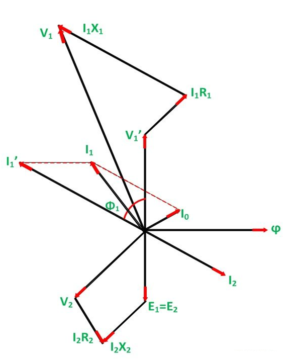
Phasor Diagram of Transformer on Capacitive Load:
The Transformer on the capacitive load (leading power factor load) is shown below in the phasor diagram.
|
Steps to draw the phasor diagram at capacitive load:
- Take flux ϕ a reference
- Induces emf E1 and E2 lags the flux by 90 degrees.
- The component of the applied voltage to the primary equal and opposite to induced emf in the primary winding. E1 is represented by V1’.
- Current I0 lags the voltage V1’ by 90 degrees.
- The power factor of the load is leading. Therefore, current I2 is drawn leading E2
- The resistance and the leakage reactance of the windings result in a voltage drop, and hence secondary terminal voltage V2 is the phasor difference of E2 and voltage drop.
V2 = E2 – voltage drops
I2 R2 is in phase with I2 and I2X2 is in quadrature with I2.
- Current I1’ is drawn equal and opposite to the current I2
- The total current I1 flowing in the primary winding is the phasor sum of I1’ and I0.
- Primary applied voltage V1 is the phasor sum of V1’ and the voltage drop in the primary winding.
V1 = V1’ + voltage drop
I1R1 is in phase with I1 and I1XI is in quadrature with I1.
- The phasor difference between V1 and I1 gives the power factor angle ϕ1 of the primary side of the transformer.
- The power factor of the secondary side depends upon the type of load connected to the transformer.
This is all about the phasor diagram on various loads.
- Losses in a Transformer
There are 2 types of losses occurring in a transformer
A) 1. Core loss or Iron loss
B) 2. Copper loss
- Core losses:
- This loss is due to the reversal of flux
- The flux set up in the core is dependent on the i/p supply
 as the i/p supply is constant in magnitude
  the flux set up will be constant and
  core losses are also constant.
 - Core losses are voltage dependent loss they can be subdivided in 2
1 Hysteresis loss
2 reedy current losses
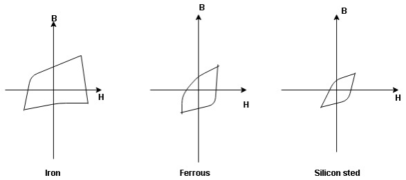
- Hysteresis loss: The iron loss occurring in the core of T/F due to the Hysteresis curve of the magnetic material used for core is called as Hysteresis loss.
Hysteresis curve is the curve as loop which shows the properly of magnetic material to lag the flux density B behind the field Intensely H
|
Above are the 3 different loops (Hysteresis of 3 diff. Materials)
 The selection of magnetic material for the construction of core depends upon Hysteresis loop of that material having tall and narrow Hysteresis loop is selected for the T/F core
 Silicon Steel
Hysteresis loss depends on fold factor
PH = KH. Bm1.67 F  V – watts
Where KH = constant (Hysteresis)
Bm = max Flux density
F = Frequency
 = Volume of core.
2. Reedy current loss:
This loss is due to the flow of reedy (circular) current in the core caused by induced emf in core
PE = Ke Bm2 f2 t2 v – watts
Where
Ke = reedy current const.
t = thickness of core
It can be reduced by using stacks of laminations instead of solid core
B] Copper loss: PCU
The Copper loss is due to resistance of the primary and secondary winding
It is load dependent / current dependent loss
As load on a transformer is variable (changing)  current changes
  copper loss is a variable loss
Primary secondary
Total C is loss = I12R12 +I22 R22
Copper loss depends upon load on T/F and is proportional to square of load current or KVA rating of transformer
 PCU
PCU  2
2 (KVA)2
F.L = full load
 PCU (at half load) =
  2 PCU F.L
= (0.5)2 PCU F.L.
Or PCu ( load) = (
 )2 PCUF.L
Find no load vtg E2
Remove the load and measure the reading of V2 meter we will get n load vtg E2
 E2 = V2 when load is absent
Now connect load and measure V2 this is now the load voltage

For each reading E2 will be same but V2 will change acc. To load
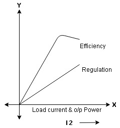
- Form Results Plot graph for efficiency and regulation against I2 and O/P power W2
|
Efficiency: it is the ratio output power to input power of transformer
Output power = input power – total loss
O/P power = KVA Or = V2 Losses = Pi + PCU (F.L) = iron + copper loss
|
Maximum efficiency – for numerical:
To achieve maximum efficiency for T/F, copper loss should equal iron loss
I.E. Pi = PCU
 =
= 
 PCU = Pi at max n
Where KVA at max n given = Full load KVA 
An Auto Transformer is a transformer with only one winding wound on a laminated core. An auto transformer is similar to a two winding transformer but differ in the way the primary and secondary winding are interrelated. A part of the winding is common to both primary and secondary sides.
On load condition, a part of the load current is obtained directly from the supply and the remaining part is obtained by transformer action. An Auto transformer works as a voltage regulator.
Explanation of Auto Transformer with Circuit Diagram
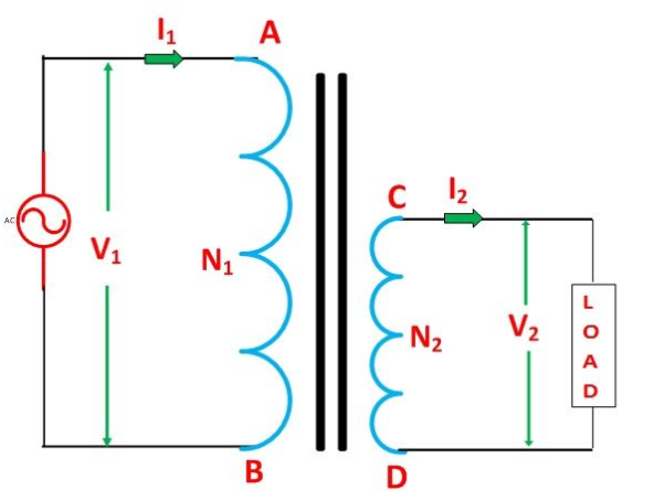
In an ordinary transformer, the primary and the secondary windings are electrically insulated from each other but connected magnetically as shown in the figure below. While in auto transformer the primary and the secondary windings are connected magnetically as well as electrically. In fact, a part of the single continuous winding is common to both primary and secondary.
|
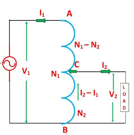
There are two types of auto transformer based on the construction. In one type of transformer, there is continuous winding with the taps brought out at convenient points determined by the desired secondary voltage. However, in another type of auto transformer, there are two or more distinct coils which are electrically connected to form a continuous winding. The construction of Auto transformer is shown in the figure below.
|
The primary winding AB from which a tapping at C is taken, such that CB acts as a secondary winding. The supply voltage is applied across AB, and the load is connected across CB. The tapping may be fixed or variable. When an AC voltage V1 is applied across AB, an alternating flux is set up in the core, as a result, an emf E1 is induced in the winding AB. A part of this induced emf is taken in the secondary circuit.
Let,
- V1 – primary applied voltage
- V2 – secondary voltage across the load
- I1 – primary current
- I2 – load current
- N1 – number of turns between A and B
- N2 – number of turns between C and B
Neglecting no-load current, leakage reactance and losses,
V1 = E1 and V2 = E2
Therefore, the transformation ratio:
As the secondary ampere-turns are opposite to primary ampere-turns, so the current I2 is in phase opposition to I1. The secondary voltage is less than the primary. Therefore current I2 is more than the current I1. Therefore, the resulting current flowing through section BC is (I2 – I1).
|
Equation (1) and (2) shows that the ampere-turns due to section BC and AC balance each other which is characteristic of the transformer action.
References:
1. V. Del Toro “ Principles of Electrical Engineering”, Prentice Hall
2. I.J. Nagrath “ Basic Electrical Engineering”, Tata McGraw Hill
3. D.F. Fitzgerald, A. Grabel Higginbotham “ Basic Electrical Engineering”, McGraw Hill
4. Mittal & Mittal “ Basic Electrical Engineering”, Tata McGraw Hill
5. B.L. Theraja and A.K. Theraja“A Text Book of Electrical Technology”, Volume - I & II
6. J. Millman & Halkias “ Electronic Devices & Circuits”, Tata McGraw Hill
7. Herbert Taub “ Digital Circuits & Microprocessors”, McGraw Hill
