Unit-4
Measuring Instruments, Electrical safety & Introduction to Power System
The instruments can be classified as
- Absolute Instruments: These instruments are those which give the values of the quantity to be measured in terms of constant of the instrument and their deflection only. No previous calibration is required. For example, tangent galvanometer, Rayleigh’s balance method for current and Lorentz method for resistance.
- Secondary Instruments: In this the electrical quantity to be measured can be determined from the deflection of the instruments only where they have been pre-calibrated by absolute instruments. Ordinary voltmeter, ammeter and wattmeter belong to this category. They are further classified as:
- Indicating Instruments- They indicate the instantaneous value of the electrical quantity being measured at the time at which it is being measured. Example Ammeter, record of the variation of such a quantity over a selected period of time.
- Integrating Instruments- They measure and register by a set of dials and pointers either the total quantity of electricity or the total amount of electrical energy supplied to a circuit in a given time. Example ammeter hour, watt hour meter.
A Permanent Magnet Moving Coil (PMMC) meter – also known as a D’Arsonval meter or galvanometer – is an instrument that allows you to measure the current through a coil by observing the coil’s angular deflection in a uniform magnetic field
A PMMC meter places a coil of wire (i.e. a conductor) in between two permanent magnets in order to create stationary magnetic field. According to Faraday’s Law of EMI, a current carrying conductor placed in a magnetic field will experience a force in the direction determined by Fleming’s Left hand rule.
PMMC instruments (i.e. D’Arsonval meters) are only used for measuring the Direct Current (DC) current.
Construction
A PMMC meter (or D’Arsonval meters) is constructed of 5 main components:
- Stationary Part or Magnet System
- Moving Coil
- Control System
- Damping System
- Meter
Stationary Part or Magnet System
In the present time we use magnets of high field intensities, high coercive force instead of using U shaped permanent magnet having soft iron pole pieces. The magnets which we are using nowadays are made up of materials like alcomax and alnico which provide high field strength.
The moving coil can freely move between the two permanent magnets as shown in the figure given below. The coil is wound with many turns of copper wire and is placed on rectangular aluminium which is pivoted on jewelled bearings.
The spring generally acts as control system for PMMC instruments. The spring also serves another important function by providing the path to lead current in and out of the coil.
The damping force hence torque is provided by movement of aluminium former in the magnetic field created by the permanent magnets.
Meter of these instruments consists of light weight pointer to have free movement and scale which is linear or uniform and varies with angle.
Let us derive a general expression for torque in permanent magnet moving coil instruments or PMMC instruments. We know that in moving coil instruments the deflecting torque is given by the expression:
- Td = NBldI where N is number of turns,
- B is magnetic flux density in air gap,
- l is the length of moving coil,
- d is the width of the moving coil,
- I is the electric current.
Now for a moving coil instrument the deflecting torque should be proportional to current, mathematically we can write Td = GI. Thus, on comparing we say G = NBIdl. At steady state we have both the controlling and deflecting torques are equal. Tc is controlling torque, on equating controlling torque with deflection torque we have
GI = K.x where x is deflection thus current is given by

Since the deflection is directly proportional to the current therefore, we need a uniform scale on the meter for measurement of current.
The electrical resistance of these shunts should not differ at higher temperature, it they should possess very low value of temperature coefficient. Also, the resistance should be time independent. Last and the most important property they should possess is that they should be able to carry high value of current without much rise in temperature. Usually, manganin is used for making DC resistance. Thus, we can say that the value of Is much greater than the value of Im as resistance of shunt is low. From the we have,

Where, Rs is resistance of shunt and Rm is the electrical resistance of the coil.

From the above two equations we can write,

Where, m is the magnifying power of the shunt.
Construction
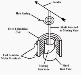
The moving element is a plate or soft iron. The plate is placed such that is moves freely in the magnetic field of stationary coil. These stationary coils are electromagnets. These magnets are temporary magnets whose field strength varies according to the amount of current passing through it. They can be used for both AC as well as DC.
Operation
These instruments use moving iron to measure the flow of current or voltages. When the iron is placed near magnetic field it is attracted towards the field. The force of attraction depends upon the strength of field.
|
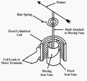
Fig 1 Moving iron type voltmeter
The stationary coil of copper or aluminium wire acts as electromagnet when current passes through it. The plate when passes through this coil increases the inductance of stationary coil. The electromagnets attract the plate. The plate passes through coil from the least reluctance path. This plate experiences a repulsion due to electromagnets. The repulsion force increases the strength of the coil inductance. This happens because the inductance and reluctances are inversely proportional to each other.
One iron vane is held fixed to the coil frame and other is free to rotate, carrying with it the pointer shaft. Two irons lie in the magnetic field produced by the coil that consists of only few turns if the instrument is an ammeter or of many turns if the instrument is a voltmeter. Current in the coil induces both vanes to become magnetized and repulsion between the similarly magnetized vanes produces a proportional rotation
The moving iron instrument can be classified as
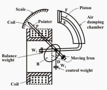
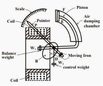
- Repulsive moving iron instrument: It has two vanes one is fixed and the other is moving. When current passes through stationary coil the vane gets magnetized and a repulsive force is generated between them. Due to this repulsion the moving coil moves away from the fixed vane.
|
Fig 2 Repulsive moving iron instrument
The spring coil provides controlling torque. The damping torque induced opposes the movement of the coil. These instruments are not affected by the direction of current flow.
- Attractive moving iron instrument: In this the iron plate is attracted from the weaker field towards the stronger one. The stationary coil is flat and has narrow opening. The flat disc of iron core is moving element. The current through stationary coil produces the magnetic field and attracts the iron coil.
|
Fig 3 Attractive moving iron instrument
The iron plate then gets attracted from low magnetic field to high magnetic field. The strength through which the iron plate is deflected is directly proportional to the current flowing through it.
Advantages:
They are low cost instruments. They are easy to assemble. They have less friction error. They are used in both AC and DC.
Construction, operating and uses of moving iron type ammeter
The torque for moving iron instrument is T= 
This can be used for both AC and DC.
The moving element is a plate or soft iron. The plate is placed such that is moves freely in the magnetic field of stationary coil. These stationary coils are electromagnets. These magnets are temporary magnets whose field strength varies according to the amount of current passing through it.
They are classified as
- Repulsive moving iron instrument: It has two vanes one is fixed and the other is moving. When current passes through stationary coil the vane gets magnetized and a repulsive force is generated between them. Due to this repulsion the moving coil moves away from the fixed vane. The spring coil provides controlling torque. The damping torque induced opposes the movement of the coil. These instruments are not affected by the direction of current flow.
- Attractive moving iron instrument: In this the iron plate is attracted from the weaker field towards the stronger one. The stationary coil is flat and has narrow opening. The flat disc of iron core is moving element. The current through stationary coil produces the magnetic field and attracts the iron coil.
Moving coil type ammeter:
The basic principle of operation is same as discussed for voltmeter in above section. The deflection torque is given as
Td= BiNlb Nm
B: flux density
i: current through coil
l: length of coil
b: breadth of coil
N: number of turns in coil
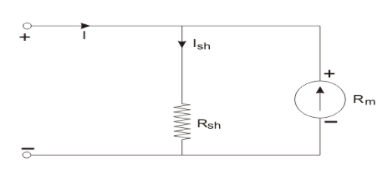
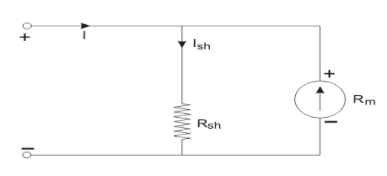
The range of instrument can be increased by adding a resistance in parallel as shown below.
|
Fig 4 Range increases by adding resistance in parallel
Rsh=
Rm: Ammeter resistance
Ish: current through shunt resistance
I: total current
Induction type Ammeter
The working principle is same as discussed in above section. They are of two types:
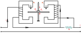
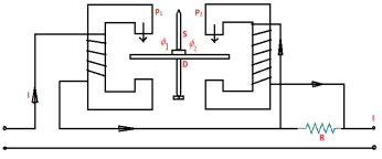
- Split phase type: It has two magnets M1 and M2 in series. The shunt resistance R is connected to M2. The current in M2 lags line current. The deflection torque is Td = φ1m φ2m sinα
|
Fig 5 Split phase type ammeter
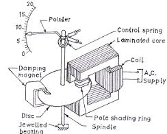
- Shaded Pole Type: In this case the exciting coil is placed on poles. The current proportion to current or voltage is measured.
|
Fig 6 Shaded pole type Ammeter
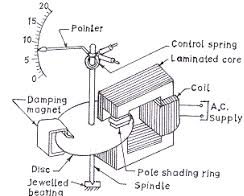
In the air gap of electromagnet aluminium disc mounted on a spindle is inserted. The spring is attached to the pointer and both are mounted on spindle. The spring provides the controlling torque.
The deflection torque is Td = φ1φ2 sinα
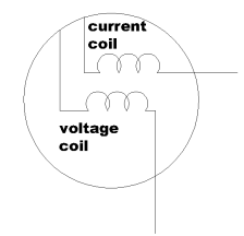
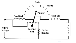
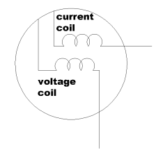
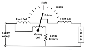
This instrument is used to measure the electric power of electric circuits. It has current and voltage coils. The wattmeter measures the power of the electric circuit.
P= VI cosφ
|
Fig 7 Single phase wattmeter
There are two types of wattmeter
- Electro-dynamometer type wattmeter
They are moving coil of instruments. The fixed coil produces the operating field. When AC flows through fixed coil magnetic field is produced. The moving coil starts moving and the pointer fluctuates. They are highly accurate.
- Induction Type wattmeter
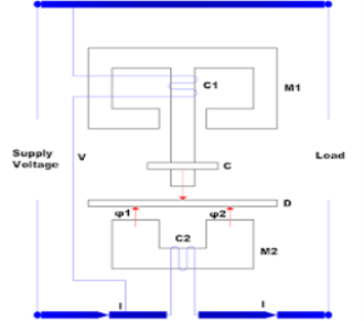
They are used for both AC and DC. It consists of two electromagnets and one is excited by the current with exciting winding. This winding is connected in series. The exciting coil is in parallel to the circuit. The winding of first magnet carries line current and other coil carries voltage. The coil connected to supply and flux lags 90o to voltage. The torque is proportional to the power in the load circuit. Due to this torque the spring fluctuates and pointer notes the reading.
Uses: They are used in laboratories, industries, transmission line and power distribution.
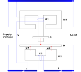
These are AC meters. These are the domestic energy meters which are widely used. They measure power in k-watthours.
|
Fig 8 Induction Type Energy Meter
It has two magnets M1 and M2. The first magnet is known as series magnet and the second magnet is known as shunt magnet. The first magnet is excited by line current. The electromagnet produces alternating flux φ1. This flux φ1 is proportional φ1 to the phase with line current. The second magnet produces the lagging flux φ2 which is proportion to supply voltage.
The two fluxes and the eddy current react and produces driving torque on the disc. The two magnets produce barking torque.
Shunt is a device which allows electric current to pass around another point in the circuit by creating a low resistance path. A shunt (aka a current shunt resistor or an ammeter shunt) is a high precision resistor which can be used to measure the current flowing through a circuit. An ammeter shunt is a very low-resistance connection between two points in an electric circuit that forms an alternative path for a portion of the current. Shunt voltage drop is used in conjunction with an ammeter to measure amperage of a circuit. Shunt is used in the electronic filter circuits as a component connecting the line and common. Diodes are also used as shunts. Where devices are especially sensitive to reverse polarity of signal or power supply, a diode may be used to protect the circuit.
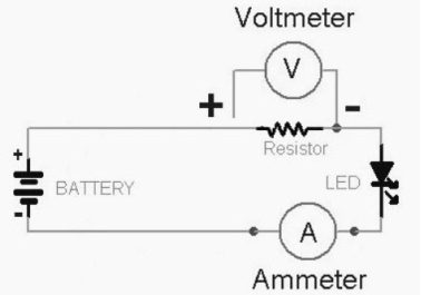
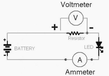
A voltage multiplier is an electrical circuit that converts AC electrical power from a lower voltage to a higher DC voltage, typically using a network of capacitors and diodes. The main function of the multiplier is to limit the current through the basic meter so that the meter current does not exceed the full-scale deflection value. The voltmeter measures the voltage across the two points of a circuit or a voltage across a circuit component.
Short circuits
The circuit that allows the electric current to pass through the random path which has low resistance is known as the short circuit. The short circuit causes the heavy current which damages the insulation of the electrical equipment. It mainly occurs when the two wire touches each other or when the insulation between the conductor breaks down. The magnitude of the short circuit current becomes thousands time larger than the normal current. During the short circuit, the voltage at the fault point diminishes to zero and high magnitude current flow through the network. The short circuit has various harmful effects on the power system.
Overloads
The overload means more than the desires load imposed on the power system network. The voltage at the overloads become diminished to a very low value, but it cannot be zero. The current in the overloaded condition is high but considerably lower than the short circuit current. The overloaded increase the temperature regarding joules, which causes burns and hence damage the electrical equipment. The overloaded condition damage the equipment of the power system. For example, Consider the inverter has a rating of 400 watts, and if the load of 800 watts is connected across it, then this will cause an overload.
Earth leakage
Electrical power systems must include devices to detect ground leakage currents of even small magnitude, and to disconnect power from the load circuit involved when such leakage currents are detected. A ground fault detector protects an electrical power system against ground leakage currents. Ground leakage is the flow of current from a live conductor to the earth through the insulation.
Key takeaway
One of the major differences between the short circuit and the overload is that the short circuit occurs because of the fault between the lines or line-to-earth whereas the overload means the equipment draw the excess of current from the supply.
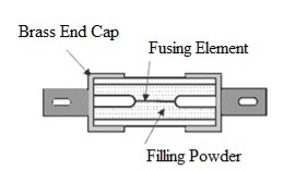
HRC fuse or high rupturing capacity fuse– In that type of fuse, the fuse wire or element can carry short circuit heavy current for a known time period. During this time if the fault gets removed, then it does not blow off. Otherwise, it blows off or melts. The enclosure of HRC fuse is either of glass or some other chemical compound.
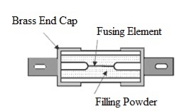
This enclosure is sufficiently airtight to avoid the effect of the atmosphere on the fuse materials. The ceramic enclosure having a metal end cap at both heads, to which fusible silver wire gets welded. There is a space within the enclosure, surrounding the fuse wire or fuse element, completely packed with a filling powder.
Construction of HRC fuse
The construction of HRC fuse includes a material that has high heat resistant body like ceramic. This ceramic body includes metal-end caps that are welded through an element that carries silver-current.
|
Fig 9 HRC Fuse
The internal space of the fuse body is filled by a filling powder material. Here the material used in this is quartz, plaster of Paris, dust, marble, chalk, etc. So, this is the reason the flow of current cannot overheat. The generated heat vaporizes the melted element. The chemical reaction will occur between filling power and silver vapor to result in high resistance material to help in reducing the arc within the fuse.
Generally, copper or silver is used as the fuse element because of its low specific resistance. This element has normally two or more sections. The fuse element normally has two or more sections that are connected through tin joints. The melting point of tin is 2400 C that is lesser than silver’s melting point of 980o C. Thus, the melting point of tin joints stops the fuse from getting high temperatures in the short circuit and overload conditions.
Operation of HRC Fuse
When the overrated current flows through the fuse element of the high rupturing capacity fuse the element is melted and vaporized.
The filling powder is of such a quantity that the chemical reaction between the silver vapor and the filling powder forms a high electrical resistance substance which very much helps in quenching the arc. HRC fuses are used to protect the circuit from short circuits in HV switchgear. Used for backup safety Used to protect electrical devices like motors, transformers, automobiles, etc. These types of fuses are used in stators of motor
Key takeaway
HRC fuses are used to protect the circuit from short circuits in HV switchgear. Used for backup safety Used to protect electrical devices like motors, transformers, automobiles, etc. These types of fuses are used in stators of motor
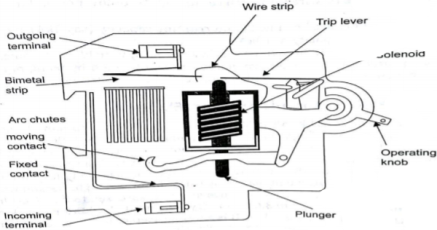
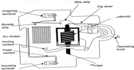
MCB is a switch which automatically turns off when the current flowing through it passes the maximum allowable limit. Generally, MCB is designed to protect against over current and over temperature faults. In MCB there are two contacts one movable and other non-movable. When the current exceeds the predefined limit, a solenoid forces the moveable contact to open and the MCB turns off, thereby stopping the current from flowing in the circuits.
It mainly consists of one bi- metallic strip, one trip coil and one hand operated on-off lever. The current in MCB flows from left side of circuit to bimetallic strip further going into the current coil, moving contact and at last through right side of circuit. When circuit is overloaded the bimetallic strip is overheated.
|
Fig 10 MCB
This deformation of bimetallic strip causes displacement in the latch. This displacement releases the spring through which the MCB is connected to the moving contact. This spring makes moving contact to open MCB.
The current coil or trip coil placed in such a manner that during SC faults, the MMF of that coil causes its plunger to hit the same latch point and force the latch to be displaced. Hence, the MCB will open in the same manner.
They are frequently used in domestic and industrial purposes. The MCB detects faults like switching, overload, short circuit protection and overload protection.
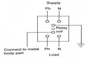
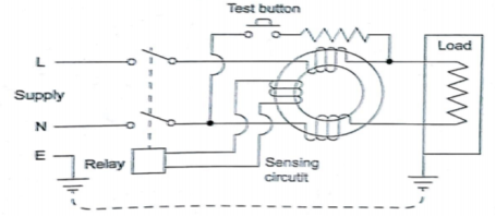
An Earth Leakage Circuits Breakers (ELCB) is a device used to directly detect currents leaking to earth from an installation and cut the power. There are two types of ELCBs:
- Voltage Earth Leakage Circuits Breaker (voltage -ELCB)
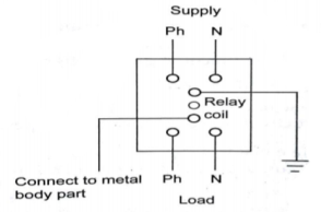
It consists of a relay coil; one end of that coil is connected to the metal body and other to the ground. When voltage on the equipment body rises to 50V (danger level) the current in the relay loop moves the relay contact by disconnecting the supply current and saves from electric shock.
|
Fig 11 Voltage-ELCB
- Current Earth Leakage Circuits Breaker (Current -ELCB)
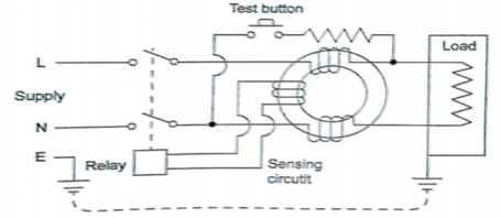
It is mostly commonly used ELCB. It consists of transformer having two primary (neutral and line wire) windings and one secondary winding. In balanced condition there is no current in secondary because the neutral wire balances the current through the phase wire.
|
Fig 12 Current-ELCB
During fault a small current flow to ground causing imbalance between line and neutral currents. As a result of which current is induced in secondary winding. The sensing circuit connected to the secondary sends signal to the tripping system and the contact is tripped.
Neutral
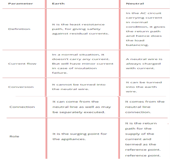
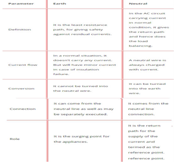
Neutral acts as a return conductor for current flow in a single-phase, two-wire (L-N) AC circuit. It completes an AC circuit. It is centre tap point of a Wye connected transformer. Hence it carries the return current back to the transformer (source). Normally this point is earthed for various reasons. In an ideal AC system, neutral and earth should be at the same potential, which means the voltage measured between the neutral and the earth should be zero.
Earth or Ground
An Earth or ground is a safety connection to protect personnel from electric shock. When a bare conductor inside a piece of equipment touches its metal body or in case of insulation failures, there is a risk of electric shock to the person who operates or touches the equipment. Earth conductors provide a low resistance path for the leakage currents to discharge, hence protecting the equipment and the personnel.
Normally conductor used for grounding a piece of equipment is sized just to carry fault current discharged on the equipment body. Well-grounded equipment avoids the risk of electric shock the person using it.
Normally the neutral point is earthed at the distribution transformer (Delta – Wye connected transformers). This helps in keeping the earth and neutral in the same potential and protects against dangerous transient voltages in neutral.
Key takeaway
|
Soil Resistivity
It is the resistance of soil to the passage of electric current. The earth resistance value (ohmic value) of an earth pit depends on soil resistivity. It is the resistance of the soil to the passage of electric current.
It varies from soil to soil. It depends on the physical composition of the soil, moisture, dissolved salts, grain size and distribution, seasonal variation, current magnitude etc. In depends on the composition of soil, Moisture content, Dissolved salts, grain size and its distribution, seasonal variation, current magnitude.
Soil Condition
Different soil conditions give different soil resistivity. Most of the soils are very poor conductors of electricity when they are completely dry. Soil resistivity is measured in ohm-meters or ohm-cm.
Moisture
Moisture has a great influence on resistivity value of soil. The resistivity of a soil can be determined by the quantity of water held by the soil and resistivity of the water itself. Conduction of electricity in soil is through water.
Dissolved salts
Pure water is poor conductor of electricity. Resistivity of soil depends on resistivity of water which in turn depends on the amount and nature of salts dissolved in it.
Climate Condition
Increase or decrease of moisture content determines the increase or decrease of soil resistivity. Thus, in dry whether resistivity will be very high and in monsoon months the resistivity will be low.
Physical Composition
Different soil composition gives different average resistivity. Based on the type of soil, the resistivity of clay soil may be in the range of 4 – 150 ohm-meter, whereas for rocky or gravel soils, the same may be well above 1000 ohm-meter.
Location of Earth Pit
The location also contributes to resistivity to a great extent. In a sloping landscape, or in a land with made up of soil, or areas which are hilly, rocky or sandy, water runs off and in dry weather conditions water table goes down very fast. In such situation back fill compound will not be able to attract moisture, as the soil around the pit would be dry.
The earth pits located in such areas must be watered at frequent intervals, particularly during dry weather conditions. Though back fill compound retains moisture under normal conditions, it gives off moisture during dry weather to the dry soil around the electrode, and in the process loses moisture over a period of time. Therefore, choose a site that is naturally not well drained.
Effect of grain size and its distribution
Grain size, its distribution and closeness of packing are also contributory factors, since they control the manner in which the moisture is held in the soil. Effect of seasonal variation on soil resistivity: Increase or decrease of moisture content in soil determines decrease or increase of soil resistivity. Thus, in dry weather resistivity will be very high and during rainy season the resistivity will be low.
Effect of current magnitude
Soil resistivity in the vicinity of ground electrode may be affected by current flowing from the electrode into the surrounding soil. The thermal characteristics and the moisture content of the soil will determine if a current of a given magnitude and duration will cause significant drying and thus increase the effect of soil resistivity.
Current Magnitude
A current of significant magnitude and duration will cause significant drying condition in soil and thus increase the soil resistivity.
Key takeaway
The thermal characteristics and the moisture content of the soil will determine if a current of a given magnitude and duration will cause significant drying and thus increase the effect of soil resistivity. Different soil conditions give different soil resistivity. Most of the soils are very poor conductors of electricity when they are completely dry.
Earthing
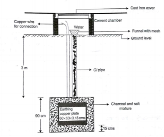
It means connecting electrical equipment to earth with very low resistance wire. This ensures safe discharge of electrical energy due to failure of the insulation line coming in contact with the casing, etc. Earthing brings the potential of the body of the equipment to zero.
The main purpose of Earthing is to protect the operating personnel from shock. Under unbalanced load maintain the line voltage. To avoid risk of fire due to leakage currents. For protecting the equipment.
Methods of Earthing:
|
Fig 13 Plate Earthing
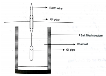
- Pipe earthing:
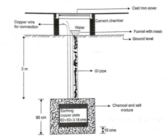
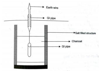
The earth’s electrode made of galvanized iron pipe with holes on surface is placed upright in wet ground. In order to maintain the earth’s resistance, the pipe is filled with mixture of salt and coal.
|
Fig 14 Pipe Earthing
This system can carry larger leakage currents compared to plate earthing method.
Power to weight ratio of 3-phase induction motor is high as compare to 1-phase IM. Means for the same amount of Mechanical Power, the size of three phase induction motor is small as compared to single phase induction motor. Hence, the overall cost of IM is reduced. Moreover, due to reduction in weight, transportation, and installation of induction motor become convenient and less space is required to accommodate the induction motor.
3-phase induction motor is self-started as the magnetic flux produced by 3-phase supply is rotating in nature with a constant magnitude. Whereas 1-ø induction motor is not self-started as the magnetic flux produced by 1-ø supply is pulsating in nature. Hence, we have to make some arrangement to make the 1-ø induction motor self-started which further increases the cost of 1-ø induction motor.
3-phase motor is having better power factor
Power to weight ratio of 3-phase transformer is high as compare to 1-ø transformer. Means for the same amount of Electric Power, the size of 3-phase transformer is small as compared to 1-ø transformer. Hence, the overall cost of a transformer gets reduced. Moreover, due to reduction in weight, transportation and installation of transformer become convenient and less space is required to accommodate the transformer.
If a fault occurs in any winding of a 3-phase transformer, the rest of two winding can be used in the open delta to serve the 3-phase load. The same is not possible in 1-ø transformer. This ability of 3-phase transformer further increases the reliability of 3-phase transformer.
A 3-phase system can be used to feed a 1-ø load, whereas vice-versa is not possible.
DC rectified from 3-phase supply is having the ripple factor 4% and DC rectified from 1-ø supply is having the ripple factor 48.2%. Mean DC rectified from 3-ø supply contains fewer ripples as compare to DC rectified from a 1-ø supply. Hence the requirement of the filter is reduced for DC rectified from a 3-phase supply. Which reduce the overall cost of converter.
Key takeaway
3-phase motor is having better power factor. 3-ø supply contains fewer ripples as compare to DC rectified from a 1-ø supply. Power to weight ratio of 3-phase transformer is high as compare to 1-ø transformer.
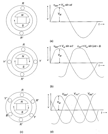
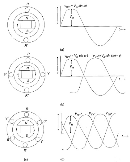
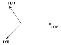
In three phase the windings are separated by 1200 each. The voltage produced in those windings are 1200 apart from each other. Below shown is one coil RR’ and two more coils YY’ and BB’ each having phase shift of 1200.
|
Fig 15 3-Phase Connection
The instantaneous value of voltages is given as
VRR’ = Vmsinωt
VYY’ = Vmsin(ωt-120)
VBB’ = Vmsin(ωt-240)
The three phase voltages are of same magnitude and frequency.
Phase sequence
The change in voltage is in order VRR’- VYY’- VBB’. So, the three-phase are changed in that order and are called as phase change.
VRR’ = Vmsinωt
VYY’ = Vmsin(ωt-120)
VBB’ = Vmsin(ωt-240)
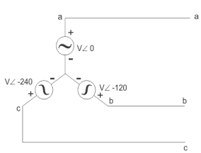
Star Connection:
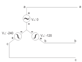
In this type similar ends are connected to common point called as neutral and having a star shape. These connections are used in case of unbalanced current flowing in the three-phase. To avoid any kind of damage we use this connection.
|
Line voltage VL =  Vphase
Line current IL = Iphase
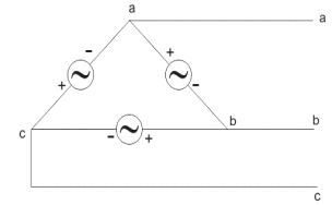
Delta Connection:
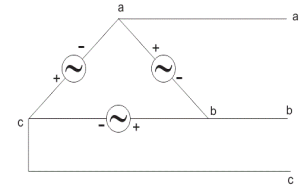
There are three wires with no neutral. They are used for short distance due to unbalanced current in circuit.
|
Line voltage VL = Vphase
Line current IL =  Iphase
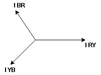
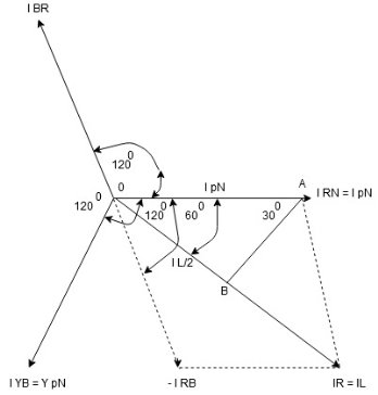
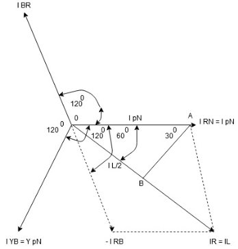
- Phasor Diagram
Consider equation ①
Note : we are getting resultant line current IR by subtracting 2 phase currents IRY and IBR  take phase currents at reference as shown
Cos 300 =
|
Fig 16 Current Phasor
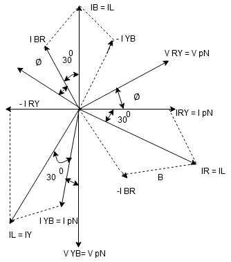
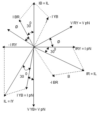
Complete phases diagram for delta connected balanced Inductive load.
|
Fig 17 Delta connected balanced Inductive load
Phase current IYB lags behind VYB which is phase voltage as the load is inductive
- Power relation for delta load star power consumed per phase
PPh = VPh IPh Cos Ø For 3 Ø total power is PT= 3 VPh IPh Cos Ø …….① For star VL
For delta VL = VPh and IL = PT
total average power P = K (watts) Total reactive power Q = K (VAR) Total Apparent power S = K (VA)
|
Example 1
Three similar resistors are connected in star across 400V 3-phase lines. Line current is 4A. Calculate the value of each resistor.
A 1)
For star connection:
IL=Iph=4A
Vph=VL/ = 400/
 = 231V
Rph= 231/4= 57.75ohm
For Delta Connection:
IL=4A
Iph= IL/
=4/ ==2.30A
Zph=400/2.30=173.9ohm
Rph= 173.9/3 = 57.97ohm
Example 2
Three identical impedances are connected in delta 3-phase supply of 400V. The line current is 30A and total power taken from the supply is 10kW. Calculate the resistance and reactance value of each impedance?
A 2) VL=Vph=400V
IL=30A
Iph=IL/ = 30/
= 30/ =17.32A
Zph=Vph/Iph= 400/17.32=23.09ohm
P= VLIL Cos Ø
Cos Ø = 10000/ 400x30 = 0.48
Sin Ø =0.88
Rph=Zph Cos Ø= 23.09x0.48=11.08ohm
Xph=Zph Sin Ø = 23.09x0.88=20.32ohm
Example 3
A star connected alternator supplies a delta connected load. The impedance of the load branch is 6+j5 ohm/phase. The line voltage is 230V. Determine the current in the load branch and power consumed by the load.
A 3)
Zph= = 7.8ohm
VL=Vph=230V
Iph=Vph/Zph=230/7.8=29.49A
Iph=IL/
IL=  Iph=
Iph= x29.49=51.07A
P= VLIL Cos Ø =
  x 230x51.07x0.768=15.62kW
Example 4
The load connected to a 3-phase supply comprise three similar coils connected in star. The line currents are 25A and the kVA and kW inputs are 18 and 10 respectively. Find the line and phase voltage, the kVAR input resistance and reactance of each coil?
A 4)
IL= 25A
P= 10000W
Cos Ø = 10/18 = 0.56
P= VLIL Cos Ø
10000= x VLx25x0.56
VL =412.39V
Vph= VL/ = 412.39/
 =238.09V
kVAR= = 14.96
Zph=238.09/25=9.52ohm
Rph=Zph Cos Ø= 9.52x0.56=5.33ohm
Xph=Zph Sin Ø = 9.52x0.83=7.88ohm
Example 4
Example 5
A balanced delta connected load consisting of three coils draws 8 A at 0.5 p.f from 100V 3-phase ac supply. If the coils are reconnected in star across the same supply. Find the line current and total power consumed?
A 5)
For Delta connection:
IL=8 A
A
Iph= IL/ = 8A
= 8A
Vph=100V
Zph=100/8=12.5ohm
Rph=Zph Cos Ø=12.5x0.5 = 6.25ohm
Xph=Zph Sin Ø = 12.5x0.866=10.825ohm
P= VLIL Cos Ø
=  x 100x 8
 x0.5=1200W
For Star Connection:
Vph= VL/ = 100/
 V=57.73V
Zph=100/8=12.5ohm
Iph=57.73/12.5=4.62A
P= VLIL Cos Ø
= x 100x 4.62x0.5
P= 400W
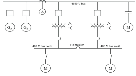
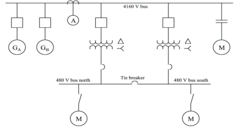
Single line diagram is the representation of a power system using the simple symbol for each component. The single line diagram of a power system is the network which shows the main connections and arrangement of the system components along with their data. In fact, the power systems are so complex that a complete conventional diagram showing all the connections is impractical. Yet, it is desirable, that there is some concise way of communicating the basic arrangement of power system components. This is done by using a Single Line Diagram (SLD). SLDs are also called One Line Diagrams.
|
Fig 18 Single Line Diagram
A generator is represented by an emf in series with an impedance. Transformers and motors are represented by their equivalent circuits. A short line is represented by its series impedance. Medium and long lines are represented by nominal PI circuits, whereas very long lines are represented by equivalent PI circuits. The shunt admittance is usually omitted in the equivalent circuit of the transformer because the magnetizing current of a transformer is usually insignificant compared with the full load current. Since the resistance of a system is very small as compared to its inductive reactance, the resistance is often omitted when making fault calculations.
The concept of bus in single line diagrams is essentially the same as the concept of a node in an electrical circuit. Just keep in mind that there is one bus for each phase. Buses are shown in SLDs as short straight lines perpendicular to transmission lines and to lines connecting equipment to the buses. In actual substations, the buses are made of aluminum or copper bars or pipes and can be several meters long. The impedance of buses is very low, practically zero, so electrically the whole bus is at the same potential.
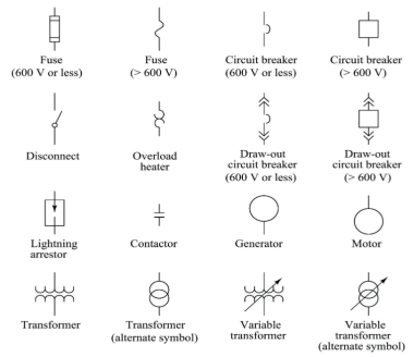
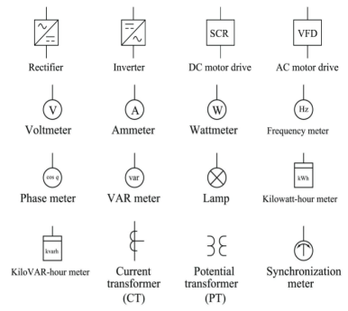
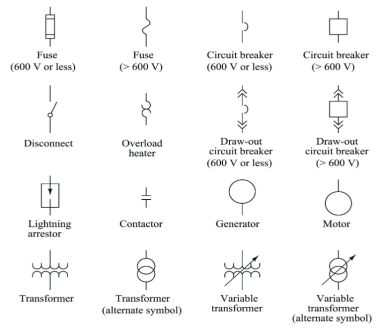
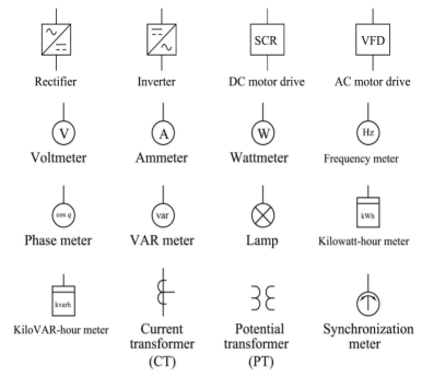
A set of commonly used single line diagram symbols are shown below.
|
Key takeaway
Single line diagram is the representation of a power system using the simple symbol for each component. The single line diagram of a power system is the network which shows the main connections and arrangement of the system components along with their data.
References:
1. V. Del Toro “ Principles of Electrical Engineering”, Prentice Hall
2. I.J. Nagrath “ Basic Electrical Engineering”, Tata McGraw Hill
3. D.F. Fitzgerald, A. Grabel Higginbotham “ Basic Electrical Engineering”, McGraw Hill
4. Mittal & Mittal “ Basic Electrical Engineering”, Tata McGraw Hill
5. B.L. Theraja and A.K. Theraja“A Text Book of Electrical Technology”, Volume - I & II
6. J. Millman & Halkias “ Electronic Devices & Circuits”, Tata McGraw Hill
7. Herbert Taub “ Digital Circuits & Microprocessors”, McGraw Hill
Unit-4
Measuring Instruments, Electrical safety & Introduction to Power System
The instruments can be classified as
- Absolute Instruments: These instruments are those which give the values of the quantity to be measured in terms of constant of the instrument and their deflection only. No previous calibration is required. For example, tangent galvanometer, Rayleigh’s balance method for current and Lorentz method for resistance.
- Secondary Instruments: In this the electrical quantity to be measured can be determined from the deflection of the instruments only where they have been pre-calibrated by absolute instruments. Ordinary voltmeter, ammeter and wattmeter belong to this category. They are further classified as:
- Indicating Instruments- They indicate the instantaneous value of the electrical quantity being measured at the time at which it is being measured. Example Ammeter, record of the variation of such a quantity over a selected period of time.
- Integrating Instruments- They measure and register by a set of dials and pointers either the total quantity of electricity or the total amount of electrical energy supplied to a circuit in a given time. Example ammeter hour, watt hour meter.
A Permanent Magnet Moving Coil (PMMC) meter – also known as a D’Arsonval meter or galvanometer – is an instrument that allows you to measure the current through a coil by observing the coil’s angular deflection in a uniform magnetic field
A PMMC meter places a coil of wire (i.e. a conductor) in between two permanent magnets in order to create stationary magnetic field. According to Faraday’s Law of EMI, a current carrying conductor placed in a magnetic field will experience a force in the direction determined by Fleming’s Left hand rule.
PMMC instruments (i.e. D’Arsonval meters) are only used for measuring the Direct Current (DC) current.
Construction
A PMMC meter (or D’Arsonval meters) is constructed of 5 main components:
- Stationary Part or Magnet System
- Moving Coil
- Control System
- Damping System
- Meter
Stationary Part or Magnet System
In the present time we use magnets of high field intensities, high coercive force instead of using U shaped permanent magnet having soft iron pole pieces. The magnets which we are using nowadays are made up of materials like alcomax and alnico which provide high field strength.
The moving coil can freely move between the two permanent magnets as shown in the figure given below. The coil is wound with many turns of copper wire and is placed on rectangular aluminium which is pivoted on jewelled bearings.
The spring generally acts as control system for PMMC instruments. The spring also serves another important function by providing the path to lead current in and out of the coil.
The damping force hence torque is provided by movement of aluminium former in the magnetic field created by the permanent magnets.
Meter of these instruments consists of light weight pointer to have free movement and scale which is linear or uniform and varies with angle.
Let us derive a general expression for torque in permanent magnet moving coil instruments or PMMC instruments. We know that in moving coil instruments the deflecting torque is given by the expression:
- Td = NBldI where N is number of turns,
- B is magnetic flux density in air gap,
- l is the length of moving coil,
- d is the width of the moving coil,
- I is the electric current.
Now for a moving coil instrument the deflecting torque should be proportional to current, mathematically we can write Td = GI. Thus, on comparing we say G = NBIdl. At steady state we have both the controlling and deflecting torques are equal. Tc is controlling torque, on equating controlling torque with deflection torque we have
GI = K.x where x is deflection thus current is given by

Since the deflection is directly proportional to the current therefore, we need a uniform scale on the meter for measurement of current.
The electrical resistance of these shunts should not differ at higher temperature, it they should possess very low value of temperature coefficient. Also, the resistance should be time independent. Last and the most important property they should possess is that they should be able to carry high value of current without much rise in temperature. Usually, manganin is used for making DC resistance. Thus, we can say that the value of Is much greater than the value of Im as resistance of shunt is low. From the we have,

Where, Rs is resistance of shunt and Rm is the electrical resistance of the coil.

From the above two equations we can write,

Where, m is the magnifying power of the shunt.
Construction
The moving element is a plate or soft iron. The plate is placed such that is moves freely in the magnetic field of stationary coil. These stationary coils are electromagnets. These magnets are temporary magnets whose field strength varies according to the amount of current passing through it. They can be used for both AC as well as DC.
Operation
These instruments use moving iron to measure the flow of current or voltages. When the iron is placed near magnetic field it is attracted towards the field. The force of attraction depends upon the strength of field.
|
Fig 1 Moving iron type voltmeter
The stationary coil of copper or aluminium wire acts as electromagnet when current passes through it. The plate when passes through this coil increases the inductance of stationary coil. The electromagnets attract the plate. The plate passes through coil from the least reluctance path. This plate experiences a repulsion due to electromagnets. The repulsion force increases the strength of the coil inductance. This happens because the inductance and reluctances are inversely proportional to each other.
One iron vane is held fixed to the coil frame and other is free to rotate, carrying with it the pointer shaft. Two irons lie in the magnetic field produced by the coil that consists of only few turns if the instrument is an ammeter or of many turns if the instrument is a voltmeter. Current in the coil induces both vanes to become magnetized and repulsion between the similarly magnetized vanes produces a proportional rotation
The moving iron instrument can be classified as
- Repulsive moving iron instrument: It has two vanes one is fixed and the other is moving. When current passes through stationary coil the vane gets magnetized and a repulsive force is generated between them. Due to this repulsion the moving coil moves away from the fixed vane.
|
Fig 2 Repulsive moving iron instrument
The spring coil provides controlling torque. The damping torque induced opposes the movement of the coil. These instruments are not affected by the direction of current flow.
- Attractive moving iron instrument: In this the iron plate is attracted from the weaker field towards the stronger one. The stationary coil is flat and has narrow opening. The flat disc of iron core is moving element. The current through stationary coil produces the magnetic field and attracts the iron coil.
|
Fig 3 Attractive moving iron instrument
The iron plate then gets attracted from low magnetic field to high magnetic field. The strength through which the iron plate is deflected is directly proportional to the current flowing through it.
Advantages:
They are low cost instruments. They are easy to assemble. They have less friction error. They are used in both AC and DC.
Construction, operating and uses of moving iron type ammeter
The torque for moving iron instrument is T= 
This can be used for both AC and DC.
The moving element is a plate or soft iron. The plate is placed such that is moves freely in the magnetic field of stationary coil. These stationary coils are electromagnets. These magnets are temporary magnets whose field strength varies according to the amount of current passing through it.
They are classified as
- Repulsive moving iron instrument: It has two vanes one is fixed and the other is moving. When current passes through stationary coil the vane gets magnetized and a repulsive force is generated between them. Due to this repulsion the moving coil moves away from the fixed vane. The spring coil provides controlling torque. The damping torque induced opposes the movement of the coil. These instruments are not affected by the direction of current flow.
- Attractive moving iron instrument: In this the iron plate is attracted from the weaker field towards the stronger one. The stationary coil is flat and has narrow opening. The flat disc of iron core is moving element. The current through stationary coil produces the magnetic field and attracts the iron coil.
Moving coil type ammeter:
The basic principle of operation is same as discussed for voltmeter in above section. The deflection torque is given as
Td= BiNlb Nm
B: flux density
i: current through coil
l: length of coil
b: breadth of coil
N: number of turns in coil
The range of instrument can be increased by adding a resistance in parallel as shown below.
|
Fig 4 Range increases by adding resistance in parallel
Rsh=
Rm: Ammeter resistance
Ish: current through shunt resistance
I: total current
Induction type Ammeter
The working principle is same as discussed in above section. They are of two types:
- Split phase type: It has two magnets M1 and M2 in series. The shunt resistance R is connected to M2. The current in M2 lags line current. The deflection torque is Td = φ1m φ2m sinα
|
Fig 5 Split phase type ammeter
- Shaded Pole Type: In this case the exciting coil is placed on poles. The current proportion to current or voltage is measured.
|
Fig 6 Shaded pole type Ammeter
In the air gap of electromagnet aluminium disc mounted on a spindle is inserted. The spring is attached to the pointer and both are mounted on spindle. The spring provides the controlling torque.
The deflection torque is Td = φ1φ2 sinα
This instrument is used to measure the electric power of electric circuits. It has current and voltage coils. The wattmeter measures the power of the electric circuit.
P= VI cosφ
|
Fig 7 Single phase wattmeter
There are two types of wattmeter
- Electro-dynamometer type wattmeter
They are moving coil of instruments. The fixed coil produces the operating field. When AC flows through fixed coil magnetic field is produced. The moving coil starts moving and the pointer fluctuates. They are highly accurate.
- Induction Type wattmeter
They are used for both AC and DC. It consists of two electromagnets and one is excited by the current with exciting winding. This winding is connected in series. The exciting coil is in parallel to the circuit. The winding of first magnet carries line current and other coil carries voltage. The coil connected to supply and flux lags 90o to voltage. The torque is proportional to the power in the load circuit. Due to this torque the spring fluctuates and pointer notes the reading.
Uses: They are used in laboratories, industries, transmission line and power distribution.
These are AC meters. These are the domestic energy meters which are widely used. They measure power in k-watthours.
|
Fig 8 Induction Type Energy Meter
It has two magnets M1 and M2. The first magnet is known as series magnet and the second magnet is known as shunt magnet. The first magnet is excited by line current. The electromagnet produces alternating flux φ1. This flux φ1 is proportional φ1 to the phase with line current. The second magnet produces the lagging flux φ2 which is proportion to supply voltage.
The two fluxes and the eddy current react and produces driving torque on the disc. The two magnets produce barking torque.
Shunt is a device which allows electric current to pass around another point in the circuit by creating a low resistance path. A shunt (aka a current shunt resistor or an ammeter shunt) is a high precision resistor which can be used to measure the current flowing through a circuit. An ammeter shunt is a very low-resistance connection between two points in an electric circuit that forms an alternative path for a portion of the current. Shunt voltage drop is used in conjunction with an ammeter to measure amperage of a circuit. Shunt is used in the electronic filter circuits as a component connecting the line and common. Diodes are also used as shunts. Where devices are especially sensitive to reverse polarity of signal or power supply, a diode may be used to protect the circuit.
A voltage multiplier is an electrical circuit that converts AC electrical power from a lower voltage to a higher DC voltage, typically using a network of capacitors and diodes. The main function of the multiplier is to limit the current through the basic meter so that the meter current does not exceed the full-scale deflection value. The voltmeter measures the voltage across the two points of a circuit or a voltage across a circuit component.
Short circuits
The circuit that allows the electric current to pass through the random path which has low resistance is known as the short circuit. The short circuit causes the heavy current which damages the insulation of the electrical equipment. It mainly occurs when the two wire touches each other or when the insulation between the conductor breaks down. The magnitude of the short circuit current becomes thousands time larger than the normal current. During the short circuit, the voltage at the fault point diminishes to zero and high magnitude current flow through the network. The short circuit has various harmful effects on the power system.
Overloads
The overload means more than the desires load imposed on the power system network. The voltage at the overloads become diminished to a very low value, but it cannot be zero. The current in the overloaded condition is high but considerably lower than the short circuit current. The overloaded increase the temperature regarding joules, which causes burns and hence damage the electrical equipment. The overloaded condition damage the equipment of the power system. For example, Consider the inverter has a rating of 400 watts, and if the load of 800 watts is connected across it, then this will cause an overload.
Earth leakage
Electrical power systems must include devices to detect ground leakage currents of even small magnitude, and to disconnect power from the load circuit involved when such leakage currents are detected. A ground fault detector protects an electrical power system against ground leakage currents. Ground leakage is the flow of current from a live conductor to the earth through the insulation.
Key takeaway
One of the major differences between the short circuit and the overload is that the short circuit occurs because of the fault between the lines or line-to-earth whereas the overload means the equipment draw the excess of current from the supply.
HRC fuse or high rupturing capacity fuse– In that type of fuse, the fuse wire or element can carry short circuit heavy current for a known time period. During this time if the fault gets removed, then it does not blow off. Otherwise, it blows off or melts. The enclosure of HRC fuse is either of glass or some other chemical compound.
This enclosure is sufficiently airtight to avoid the effect of the atmosphere on the fuse materials. The ceramic enclosure having a metal end cap at both heads, to which fusible silver wire gets welded. There is a space within the enclosure, surrounding the fuse wire or fuse element, completely packed with a filling powder.
Construction of HRC fuse
The construction of HRC fuse includes a material that has high heat resistant body like ceramic. This ceramic body includes metal-end caps that are welded through an element that carries silver-current.
|
Fig 9 HRC Fuse
The internal space of the fuse body is filled by a filling powder material. Here the material used in this is quartz, plaster of Paris, dust, marble, chalk, etc. So, this is the reason the flow of current cannot overheat. The generated heat vaporizes the melted element. The chemical reaction will occur between filling power and silver vapor to result in high resistance material to help in reducing the arc within the fuse.
Generally, copper or silver is used as the fuse element because of its low specific resistance. This element has normally two or more sections. The fuse element normally has two or more sections that are connected through tin joints. The melting point of tin is 2400 C that is lesser than silver’s melting point of 980o C. Thus, the melting point of tin joints stops the fuse from getting high temperatures in the short circuit and overload conditions.
Operation of HRC Fuse
When the overrated current flows through the fuse element of the high rupturing capacity fuse the element is melted and vaporized.
The filling powder is of such a quantity that the chemical reaction between the silver vapor and the filling powder forms a high electrical resistance substance which very much helps in quenching the arc. HRC fuses are used to protect the circuit from short circuits in HV switchgear. Used for backup safety Used to protect electrical devices like motors, transformers, automobiles, etc. These types of fuses are used in stators of motor
Key takeaway
HRC fuses are used to protect the circuit from short circuits in HV switchgear. Used for backup safety Used to protect electrical devices like motors, transformers, automobiles, etc. These types of fuses are used in stators of motor
MCB is a switch which automatically turns off when the current flowing through it passes the maximum allowable limit. Generally, MCB is designed to protect against over current and over temperature faults. In MCB there are two contacts one movable and other non-movable. When the current exceeds the predefined limit, a solenoid forces the moveable contact to open and the MCB turns off, thereby stopping the current from flowing in the circuits.
It mainly consists of one bi- metallic strip, one trip coil and one hand operated on-off lever. The current in MCB flows from left side of circuit to bimetallic strip further going into the current coil, moving contact and at last through right side of circuit. When circuit is overloaded the bimetallic strip is overheated.
|
Fig 10 MCB
This deformation of bimetallic strip causes displacement in the latch. This displacement releases the spring through which the MCB is connected to the moving contact. This spring makes moving contact to open MCB.
The current coil or trip coil placed in such a manner that during SC faults, the MMF of that coil causes its plunger to hit the same latch point and force the latch to be displaced. Hence, the MCB will open in the same manner.
They are frequently used in domestic and industrial purposes. The MCB detects faults like switching, overload, short circuit protection and overload protection.
An Earth Leakage Circuits Breakers (ELCB) is a device used to directly detect currents leaking to earth from an installation and cut the power. There are two types of ELCBs:
- Voltage Earth Leakage Circuits Breaker (voltage -ELCB)
It consists of a relay coil; one end of that coil is connected to the metal body and other to the ground. When voltage on the equipment body rises to 50V (danger level) the current in the relay loop moves the relay contact by disconnecting the supply current and saves from electric shock.
|
Fig 11 Voltage-ELCB
- Current Earth Leakage Circuits Breaker (Current -ELCB)
It is mostly commonly used ELCB. It consists of transformer having two primary (neutral and line wire) windings and one secondary winding. In balanced condition there is no current in secondary because the neutral wire balances the current through the phase wire.
|
Fig 12 Current-ELCB
During fault a small current flow to ground causing imbalance between line and neutral currents. As a result of which current is induced in secondary winding. The sensing circuit connected to the secondary sends signal to the tripping system and the contact is tripped.
Neutral
Neutral acts as a return conductor for current flow in a single-phase, two-wire (L-N) AC circuit. It completes an AC circuit. It is centre tap point of a Wye connected transformer. Hence it carries the return current back to the transformer (source). Normally this point is earthed for various reasons. In an ideal AC system, neutral and earth should be at the same potential, which means the voltage measured between the neutral and the earth should be zero.
Earth or Ground
An Earth or ground is a safety connection to protect personnel from electric shock. When a bare conductor inside a piece of equipment touches its metal body or in case of insulation failures, there is a risk of electric shock to the person who operates or touches the equipment. Earth conductors provide a low resistance path for the leakage currents to discharge, hence protecting the equipment and the personnel.
Normally conductor used for grounding a piece of equipment is sized just to carry fault current discharged on the equipment body. Well-grounded equipment avoids the risk of electric shock the person using it.
Normally the neutral point is earthed at the distribution transformer (Delta – Wye connected transformers). This helps in keeping the earth and neutral in the same potential and protects against dangerous transient voltages in neutral.
Key takeaway
|
Soil Resistivity
It is the resistance of soil to the passage of electric current. The earth resistance value (ohmic value) of an earth pit depends on soil resistivity. It is the resistance of the soil to the passage of electric current.
It varies from soil to soil. It depends on the physical composition of the soil, moisture, dissolved salts, grain size and distribution, seasonal variation, current magnitude etc. In depends on the composition of soil, Moisture content, Dissolved salts, grain size and its distribution, seasonal variation, current magnitude.
Soil Condition
Different soil conditions give different soil resistivity. Most of the soils are very poor conductors of electricity when they are completely dry. Soil resistivity is measured in ohm-meters or ohm-cm.
Moisture
Moisture has a great influence on resistivity value of soil. The resistivity of a soil can be determined by the quantity of water held by the soil and resistivity of the water itself. Conduction of electricity in soil is through water.
Dissolved salts
Pure water is poor conductor of electricity. Resistivity of soil depends on resistivity of water which in turn depends on the amount and nature of salts dissolved in it.
Climate Condition
Increase or decrease of moisture content determines the increase or decrease of soil resistivity. Thus, in dry whether resistivity will be very high and in monsoon months the resistivity will be low.
Physical Composition
Different soil composition gives different average resistivity. Based on the type of soil, the resistivity of clay soil may be in the range of 4 – 150 ohm-meter, whereas for rocky or gravel soils, the same may be well above 1000 ohm-meter.
Location of Earth Pit
The location also contributes to resistivity to a great extent. In a sloping landscape, or in a land with made up of soil, or areas which are hilly, rocky or sandy, water runs off and in dry weather conditions water table goes down very fast. In such situation back fill compound will not be able to attract moisture, as the soil around the pit would be dry.
The earth pits located in such areas must be watered at frequent intervals, particularly during dry weather conditions. Though back fill compound retains moisture under normal conditions, it gives off moisture during dry weather to the dry soil around the electrode, and in the process loses moisture over a period of time. Therefore, choose a site that is naturally not well drained.
Effect of grain size and its distribution
Grain size, its distribution and closeness of packing are also contributory factors, since they control the manner in which the moisture is held in the soil. Effect of seasonal variation on soil resistivity: Increase or decrease of moisture content in soil determines decrease or increase of soil resistivity. Thus, in dry weather resistivity will be very high and during rainy season the resistivity will be low.
Effect of current magnitude
Soil resistivity in the vicinity of ground electrode may be affected by current flowing from the electrode into the surrounding soil. The thermal characteristics and the moisture content of the soil will determine if a current of a given magnitude and duration will cause significant drying and thus increase the effect of soil resistivity.
Current Magnitude
A current of significant magnitude and duration will cause significant drying condition in soil and thus increase the soil resistivity.
Key takeaway
The thermal characteristics and the moisture content of the soil will determine if a current of a given magnitude and duration will cause significant drying and thus increase the effect of soil resistivity. Different soil conditions give different soil resistivity. Most of the soils are very poor conductors of electricity when they are completely dry.
Earthing
It means connecting electrical equipment to earth with very low resistance wire. This ensures safe discharge of electrical energy due to failure of the insulation line coming in contact with the casing, etc. Earthing brings the potential of the body of the equipment to zero.
The main purpose of Earthing is to protect the operating personnel from shock. Under unbalanced load maintain the line voltage. To avoid risk of fire due to leakage currents. For protecting the equipment.
Methods of Earthing:
|
Fig 13 Plate Earthing
- Pipe earthing:
The earth’s electrode made of galvanized iron pipe with holes on surface is placed upright in wet ground. In order to maintain the earth’s resistance, the pipe is filled with mixture of salt and coal.
|
Fig 14 Pipe Earthing
This system can carry larger leakage currents compared to plate earthing method.
Power to weight ratio of 3-phase induction motor is high as compare to 1-phase IM. Means for the same amount of Mechanical Power, the size of three phase induction motor is small as compared to single phase induction motor. Hence, the overall cost of IM is reduced. Moreover, due to reduction in weight, transportation, and installation of induction motor become convenient and less space is required to accommodate the induction motor.
3-phase induction motor is self-started as the magnetic flux produced by 3-phase supply is rotating in nature with a constant magnitude. Whereas 1-ø induction motor is not self-started as the magnetic flux produced by 1-ø supply is pulsating in nature. Hence, we have to make some arrangement to make the 1-ø induction motor self-started which further increases the cost of 1-ø induction motor.
3-phase motor is having better power factor
Power to weight ratio of 3-phase transformer is high as compare to 1-ø transformer. Means for the same amount of Electric Power, the size of 3-phase transformer is small as compared to 1-ø transformer. Hence, the overall cost of a transformer gets reduced. Moreover, due to reduction in weight, transportation and installation of transformer become convenient and less space is required to accommodate the transformer.
If a fault occurs in any winding of a 3-phase transformer, the rest of two winding can be used in the open delta to serve the 3-phase load. The same is not possible in 1-ø transformer. This ability of 3-phase transformer further increases the reliability of 3-phase transformer.
A 3-phase system can be used to feed a 1-ø load, whereas vice-versa is not possible.
DC rectified from 3-phase supply is having the ripple factor 4% and DC rectified from 1-ø supply is having the ripple factor 48.2%. Mean DC rectified from 3-ø supply contains fewer ripples as compare to DC rectified from a 1-ø supply. Hence the requirement of the filter is reduced for DC rectified from a 3-phase supply. Which reduce the overall cost of converter.
Key takeaway
3-phase motor is having better power factor. 3-ø supply contains fewer ripples as compare to DC rectified from a 1-ø supply. Power to weight ratio of 3-phase transformer is high as compare to 1-ø transformer.
In three phase the windings are separated by 1200 each. The voltage produced in those windings are 1200 apart from each other. Below shown is one coil RR’ and two more coils YY’ and BB’ each having phase shift of 1200.
|
Fig 15 3-Phase Connection
The instantaneous value of voltages is given as
VRR’ = Vmsinωt
VYY’ = Vmsin(ωt-120)
VBB’ = Vmsin(ωt-240)
The three phase voltages are of same magnitude and frequency.
Phase sequence
The change in voltage is in order VRR’- VYY’- VBB’. So, the three-phase are changed in that order and are called as phase change.
VRR’ = Vmsinωt
VYY’ = Vmsin(ωt-120)
VBB’ = Vmsin(ωt-240)
Star Connection:
In this type similar ends are connected to common point called as neutral and having a star shape. These connections are used in case of unbalanced current flowing in the three-phase. To avoid any kind of damage we use this connection.
|
Line voltage VL =  Vphase
Line current IL = Iphase
Delta Connection:
There are three wires with no neutral. They are used for short distance due to unbalanced current in circuit.
|
Line voltage VL = Vphase
Line current IL =  Iphase
- Phasor Diagram
Consider equation ①
Note : we are getting resultant line current IR by subtracting 2 phase currents IRY and IBR  take phase currents at reference as shown
Cos 300 =
|
Fig 16 Current Phasor
Complete phases diagram for delta connected balanced Inductive load.
|
Fig 17 Delta connected balanced Inductive load
Phase current IYB lags behind VYB which is phase voltage as the load is inductive
- Power relation for delta load star power consumed per phase
PPh = VPh IPh Cos Ø For 3 Ø total power is PT= 3 VPh IPh Cos Ø …….① For star VL
For delta VL = VPh and IL = PT
total average power P = K (watts) Total reactive power Q = K (VAR) Total Apparent power S = K (VA)
|
Example 1
Three similar resistors are connected in star across 400V 3-phase lines. Line current is 4A. Calculate the value of each resistor.
A 1)
For star connection:
IL=Iph=4A
Vph=VL/ = 400/
 = 231V
Rph= 231/4= 57.75ohm
For Delta Connection:
IL=4A
Iph= IL/
=4/ ==2.30A
Zph=400/2.30=173.9ohm
Rph= 173.9/3 = 57.97ohm
Example 2
Three identical impedances are connected in delta 3-phase supply of 400V. The line current is 30A and total power taken from the supply is 10kW. Calculate the resistance and reactance value of each impedance?
A 2) VL=Vph=400V
IL=30A
Iph=IL/ = 30/
= 30/ =17.32A
Zph=Vph/Iph= 400/17.32=23.09ohm
P= VLIL Cos Ø
Cos Ø = 10000/ 400x30 = 0.48
Sin Ø =0.88
Rph=Zph Cos Ø= 23.09x0.48=11.08ohm
Xph=Zph Sin Ø = 23.09x0.88=20.32ohm
Example 3
A star connected alternator supplies a delta connected load. The impedance of the load branch is 6+j5 ohm/phase. The line voltage is 230V. Determine the current in the load branch and power consumed by the load.
A 3)
Zph= = 7.8ohm
VL=Vph=230V
Iph=Vph/Zph=230/7.8=29.49A
Iph=IL/
IL=  Iph=
Iph= x29.49=51.07A
P= VLIL Cos Ø =
  x 230x51.07x0.768=15.62kW
Example 4
The load connected to a 3-phase supply comprise three similar coils connected in star. The line currents are 25A and the kVA and kW inputs are 18 and 10 respectively. Find the line and phase voltage, the kVAR input resistance and reactance of each coil?
A 4)
IL= 25A
P= 10000W
Cos Ø = 10/18 = 0.56
P= VLIL Cos Ø
10000= x VLx25x0.56
VL =412.39V
Vph= VL/ = 412.39/
 =238.09V
kVAR= = 14.96
Zph=238.09/25=9.52ohm
Rph=Zph Cos Ø= 9.52x0.56=5.33ohm
Xph=Zph Sin Ø = 9.52x0.83=7.88ohm
Example 4
Example 5
A balanced delta connected load consisting of three coils draws 8 A at 0.5 p.f from 100V 3-phase ac supply. If the coils are reconnected in star across the same supply. Find the line current and total power consumed?
A 5)
For Delta connection:
IL=8 A
A
Iph= IL/ = 8A
= 8A
Vph=100V
Zph=100/8=12.5ohm
Rph=Zph Cos Ø=12.5x0.5 = 6.25ohm
Xph=Zph Sin Ø = 12.5x0.866=10.825ohm
P= VLIL Cos Ø
=  x 100x 8
 x0.5=1200W
For Star Connection:
Vph= VL/ = 100/
 V=57.73V
Zph=100/8=12.5ohm
Iph=57.73/12.5=4.62A
P= VLIL Cos Ø
= x 100x 4.62x0.5
P= 400W
Single line diagram is the representation of a power system using the simple symbol for each component. The single line diagram of a power system is the network which shows the main connections and arrangement of the system components along with their data. In fact, the power systems are so complex that a complete conventional diagram showing all the connections is impractical. Yet, it is desirable, that there is some concise way of communicating the basic arrangement of power system components. This is done by using a Single Line Diagram (SLD). SLDs are also called One Line Diagrams.
|
Fig 18 Single Line Diagram
A generator is represented by an emf in series with an impedance. Transformers and motors are represented by their equivalent circuits. A short line is represented by its series impedance. Medium and long lines are represented by nominal PI circuits, whereas very long lines are represented by equivalent PI circuits. The shunt admittance is usually omitted in the equivalent circuit of the transformer because the magnetizing current of a transformer is usually insignificant compared with the full load current. Since the resistance of a system is very small as compared to its inductive reactance, the resistance is often omitted when making fault calculations.
The concept of bus in single line diagrams is essentially the same as the concept of a node in an electrical circuit. Just keep in mind that there is one bus for each phase. Buses are shown in SLDs as short straight lines perpendicular to transmission lines and to lines connecting equipment to the buses. In actual substations, the buses are made of aluminum or copper bars or pipes and can be several meters long. The impedance of buses is very low, practically zero, so electrically the whole bus is at the same potential.
A set of commonly used single line diagram symbols are shown below.
|
Key takeaway
Single line diagram is the representation of a power system using the simple symbol for each component. The single line diagram of a power system is the network which shows the main connections and arrangement of the system components along with their data.
References:
1. V. Del Toro “ Principles of Electrical Engineering”, Prentice Hall
2. I.J. Nagrath “ Basic Electrical Engineering”, Tata McGraw Hill
3. D.F. Fitzgerald, A. Grabel Higginbotham “ Basic Electrical Engineering”, McGraw Hill
4. Mittal & Mittal “ Basic Electrical Engineering”, Tata McGraw Hill
5. B.L. Theraja and A.K. Theraja“A Text Book of Electrical Technology”, Volume - I & II
6. J. Millman & Halkias “ Electronic Devices & Circuits”, Tata McGraw Hill
7. Herbert Taub “ Digital Circuits & Microprocessors”, McGraw Hill
