UNIT-1
Basic Concepts
When a single agency is acting on body then it is known as force. But when numbers of forces are acting on the body simultaneously, then it is known “System of force”.
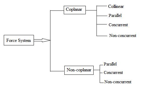
Types of Force System
1. Co-planer Forces
2. Non Co-planer Forces
3. Co-linear Forces
4. Non Co-linear Forces
5. Concurrent Forces
6. Non Concurrent Forces
7. Parallel Forces (Like & unlike)
8. Coplanar Concurrent Forces
9. Coplanar Non Concurrent Forces
10. Non Coplanar Concurrent Forces
11. Non Coplanar Non Concurrent Forces
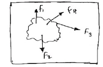
1. Co – planer Force System / Forces:- The forces whose line of action lies on the same plane are called as Co-planer Forces.
The forces which are acting in the same plane are known as co-planer forces.
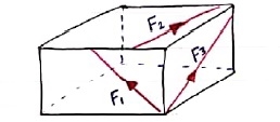
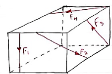
2. Non Co-planer Force System / Forces:- - A forces whose line of action does not lie in the same plane ( i.e. lie in different planes ) - Forces which are acting in the different planes known as non-co-planer forces (system).
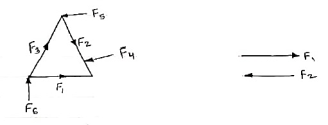
3. Co-linear force system / Forces:- - The forces whose line of action lies on the same line are called as co-linear forces. - The forces which are acting along the same straight line are called as co-linear forces.
4. Non – Collinear Forces / force system:- - The forces which are not acting along the same straight line are known as non-co-linear forces. - The forces whose line of action doesn’t lie on the same line.
F2
5. Concurrent forces / Force system:- - The forces whose line of action meets at one common point are called concurrent forces. - The forces which are passing through a common point are concurrent forces. - The forces which meets at one point are concurrent forces. 6. Non Concurrent force system / forces:- - The forces which are not passing through common point OR - The forces whose line of action does not meet at common point OR - The force which does not meet at one point is called as non-concurrent forces.
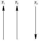
7. Parallel Forces / Force system: The forces whose lines of actions are parallel to each other are called as parallel forces. a) Like parallel Forces:- The forces whose lines of actions are parallel to each other and having same direction are called like parallel forces. Forces which are parallel to each other & acting in same direction are called as Like parallel forces.
F1 F2 F3
b. Unlike parallel Forces: The forces which are parallel to each other but having different directions or The forces which are parallel to each other & acting in opposite direction are called as unlike parallel forces.
F1 F2 F3 F4 F5
8. Coplanar concurrent forces:- The forces which meets at one point & their lines of action also lie on the same plane are called as coplanar concurrent force system.
9. Coplanar non-concurrent forces:- The forces which do not meet at one point but their line of action lies on the same plane are known as coplanar non-concurrent system of force.
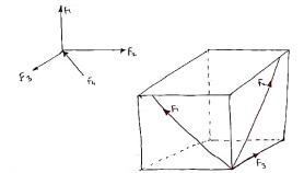
10. Non Coplanar concurrent forces:- The forces which meets at one point but their line of action do not lie on the same plane are known as non-coplanar concurrent forces.
11. Non coplanar non-concurrent forces:- Their forces which do not meet at one point & their lines of actions do not lie on the same plane are called as non - coplanar non-concurrent forces.
|
Moment:- The turning effect produced by a force on the body on which it acts is called as Moment. Moment of force about any point is the product of magnitude of force and perpendicular distance of force from the point about which moment is to be taken.
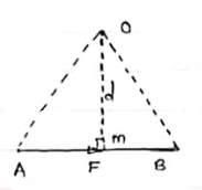
Let force F is applied at point A as shown & O is any point about which we want to take moment. Thus from point O, draw OM line perpendicular to the line of action of force. OM = d = Perpendicular distance between Force & point O. Moment = M = F x d Graphical representation of Moment:- - Select suitable scale to locate the force graphically. - Draw a line parallel to line of action of force. Length of this line can be calculated from selected scale.
- Now let O is the moment centre & OM = d = perpendicular distance By definition, Mo = F x d
Now join OA & OB, then In Δ OAB Area (ΔOAB) = ½ x AB x OM 2 (Area of ΔOAB) = F xd = Mo Thus the moment of any force about any point is numerically equal to twice area of triangle in which base represents force & height represents the perpendicular distance.
|
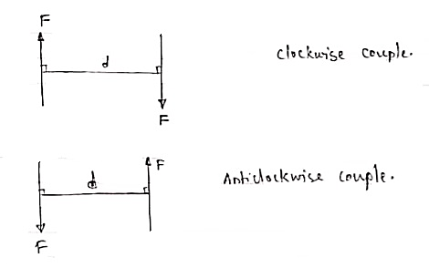
A pair of two equal and opposite (unlike) parallel forces (of same magnitude) is known as couple. Properties of Couple:- 1. Two unlike parallel, non-collinear forces of same magnitude will form couple. 2. Resultant of couple is always zero. 3. Moment of couple is product of one of the force & lever arm of couple. M = F x d Lever arm of couple = ḻlar distance between couple forces. 4. Couple cannot be balanced by single force. 5. Couple can be balanced only by another couple of opposite nature.
For example
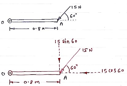
Solution:- Resolving force at point B & then taking the moment about point O, M0 = (15 Cos 60 x 0) + (15 Sin 60 x 0.8)
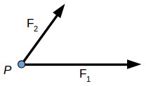
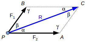
M0 = 10.39 N.m Resultant Force:- If number of forces are acting simultaneously on a body, then it is possible to find out single force which could replace them, i.e. which would produce the same effect as produced by all given forces. This single force is called as Resultant force. OR It is a single force which produces the same effect that is produced by number of forces when acting together. Resultant is denoted by (R) In mechanics we deal with two types of quantities (variables): scalar and vector variables. Scalar variables have only magnitude, for example: length, mass, temperature, time. Vector variables have magnitude and direction, for example: speed, force, torque. The direction of the vector is defined by the angles of the force witch each axis. The vector variables are usually represented using bold symbols with arrows on top. Several forces can act on a body or point, each force having different direction and magnitude. In engineering the focus is on the resultant force acting on the body. The resultant of concurrent forces (acting in the same plane) can be found using the parallelogram law, the triangle rule or the polygon rule. Two or more forces are concurrent is their direction crosses through a common point. For example, two concurrent forces F1 and F2 are acting on the same point P. In order to find their resultant R, we can apply either the parallelogram law or triangle rule. The resultant force is the vector sum between the components: R→=F1−→+F2−→
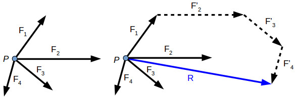
If there are several forces acting on the same point, we can apply the polygon rule to find their resultant. R→=F1−→+F2−→+F3−→+F4−→
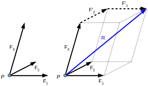
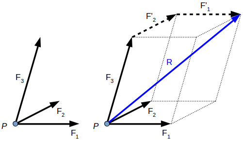
The resultant force can be determined also for three-dimensional force systems, by using the polygon rule. R→=F1−→+F2−→+F3−→
The parallelogram law, triangle rule and polygon rule are geometric methods to find the force resultant. We can draw the force resultant but we don’t know precisely its magnitude and direction. In order to calculate the magnitude and direction of a resultant force or to calculate the value of one force component or another, we can use the law of sine’s and the law of cosines.
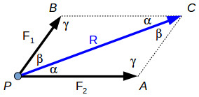
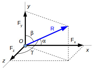
The diagonal of the parallelogram PBCA is the resultant force R, which forms two scalene triangles with the forces F1 and F2. Since the sum of all the angles within a triangle is 180°, we can write γ function of α and β. γ=180∘–α–β ………….(1) The law of sine’s gives the relationship between the forces and the angles: F1/ sin (α) = F2 / sin (β) = R / sin(180∘–α–β)………(2) The law of cosines will give us the following relationship: R= √ (F21+F22–2⋅F1⋅F2⋅cos (180∘–α–β)…….. (3) The resultant force can also be calculated analytical, using force projections. Using the force projection method, we can calculate the magnitude and direction angles of the resultant force. In the image above we have a resultant force R and its projections on each axis:
Fx – the projection of R on the x-axis
The magnitude of the resultant force is: R= √ (F2x+F2y+F2z)………….(4) Each axis resultant can be expressed function of the resultant R: Fx = R⋅cos(α) Fy = =R⋅cos(β) Fz= R⋅cos (γ) Replacing (4) in the equations above gives the angles with each axis (as trigonometric functions): Cos (α) = Fx / F2x+F2y+F2z Cos (β) =√ (Fy / F2x+F2y+F2z) Cos (γ) = √ (Fz / F2x+F2y+F2z) The force projection method can also be used for co-planar (x, y-axis) force resultant calculations. |
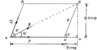
Law of parallelogram of forces for two dimensional forces:- If two forces acting simultaneously on a particle, be represented in magnitude & direction by two adjacent sides of parallelogram, then the diagonal passing through the point of intersection of two forces will represent the resultant in magnitude & direction
Consider two forces P & Q acting at a point represented by two sides OA & OC of parallelogram OABC. Let, θ is the angle between two forces P & Q. α be the angle between Force P & Resultant R. Let’s draw a line BM perpendicular to OC which intersects OC at M. In Δ CMB Sin θ = BM / BC = BM / Q BM = Q Sin θ Also, Cos θ = CM / BC = CM / Q CM = Q Cos θ Now in Δ OMB, We have, (OB) 2 = (OM) 2 + (BM)2 R2 = (OC + CM) 2 + (BM)2 R2 = (P + Q Cos θ) 2 + (Q Sin θ)2 = P2 + 2PQ Cos θ + Q2 Cos2 θ+ Q2 Sin2 θ = P2 + 2PQ Cos θ + Q2(Cos2 θ+ Q2 Sin2 θ) = P2 + 2PQ Cos θ + Q2
R = √P2 + Q2 + 2PQ Cos θ . . . . Magnitude
Tanα = Q Sin θ / P + Q Cos θ . . . . Direction
The resultant force can be determined also for three-dimensional force systems, by using the polygon rule. R→=F1−→+F2−→+F3−→ The parallelogram law, triangle rule and polygon rule are geometric methods to find the force resultant. We can draw the force resultant but we don’t know precisely its magnitude and direction. In order to calculate the magnitude and direction of a resultant force or to calculate the value of one force component or another, we can use the law of sine’s and the law of cosines. The diagonal of the parallelogram PBCA is the resultant force R, which forms two scalene triangles with the forces F1 and F2. Since the sum of all the angles within a triangle is 180°, we can write γ function of α and β. γ=180∘–α–β (1) The law of sine’s gives the relationship between the forces and the angles: F1sin (α) = F2sin (β)=Rsin(180∘–α–β)(2) The law of cosines will give us the following relationship: R=√ (F21+F22–2⋅F1⋅F2⋅cos (180∘–α–β)) −−−−−−−−−−−−−−−−−−−−−−−−−−−− (3)
|
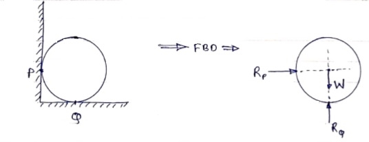
To draw the free body diagram, we have to remove all the restrictions like wall, floor, hinge, any other support and replace them by reactions which these support extents on the body. Ex – 1) Draw FBD of a bar supported and loaded as shown below.
2) Draw FBD of sphere supported as shown below.
A free-body diagram is a sketch of an object of interest with all the surrounding objects stripped away and all of the forces acting on the body shown. The drawing of a free-body diagram is an important step in the solving of mechanics problems since it helps to visualize all the forces acting on a single object. The net external force acting on the object must be obtained in order to apply Newton's Second Law to the motion of the object. A free-body diagram or isolated-body diagram is useful in problems involving equilibrium of forces. Free-body diagrams are useful for setting up standard mechanics problems.
|
2. Hinge support
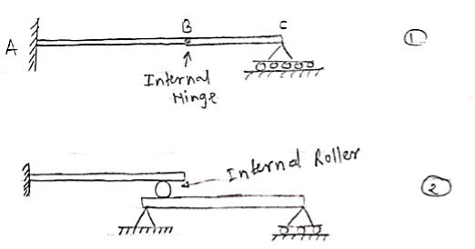
3. Internal Hinge: -
Internal Hinge
Reactions at internal Hinge 4. Fixed support: - Fixed support offers three reactions as shown in figure below. - Reaction in horizontal direction. - Reaction in vertical direction. - Moment (fixing moment)
Fixed Support
|
Condition for Equilibrium: R = 0 { ∑M = 0
|
When a mechanics problem or system has more than one force acting, it is known as a ‘force system’ or ‘system of force’.
Fig.2.2 Force System 2.3.1 Collinear Force System When the lines of action of all the forces of a system act along the same line, this force system is called collinear force system.
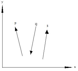
Fig.2.3 Force System 2.3.2 Parallel Forces
Fig.2.4 Force System
2.3.3 Coplanar Force System When the lines of action of a set of forces lie in a single plane is called coplanar force system. 2.3.4 Non-Coplanar Force System When the line of action of all the forces do not lie in one plane, is called Non-coplanar force system
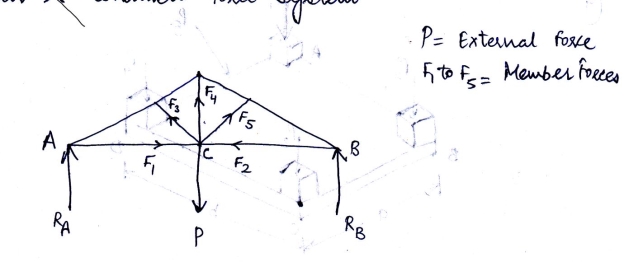
Fig.2.5 Force System 2.3.5 Concurrent Force System The forces when extended pass through a single point and the point is called point of concurrency. The lines of actions of all forces meet at the point of concurrency. Concurrent forces may or may not be coplanar. 2.3.6 Non-concurrent Force System When the forces of a system do not meet at a common point of concurrency, this type of force system is called non-concurrent force system. Parallel forces are the example of this type of force system. Non-concurrent forces may be coplanar or non-coplanar. 2.3.7 Coplanar and concurrent force system A force system in which all the forces lie in a single plane and meet at one point, For example, forces acting at a joint of a roof truss (see fig.2.6) P = External force F1 to F5 = Member forces (internal) RA and RB = Reactions C = Point of concurrency
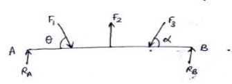
Fig.2.6 Coplanar concurrent force system 2.3.8 Coplanar and non-concurrent force system These forces do not meet at a common point; however, they lie in a single plane, for example, forces acting on a beam as shown in Fig.2.7:
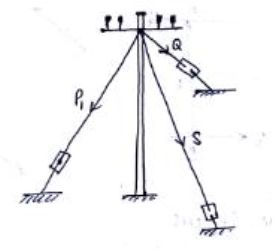
Fig.2.7 Coplanar non-concurrent force system 2.3.9 Non-coplanar and concurrent force system In this system, the forces lie in different planes but pass through a single point. Example is forces acting at the top end of an electrical pole (see Fig.2.8)
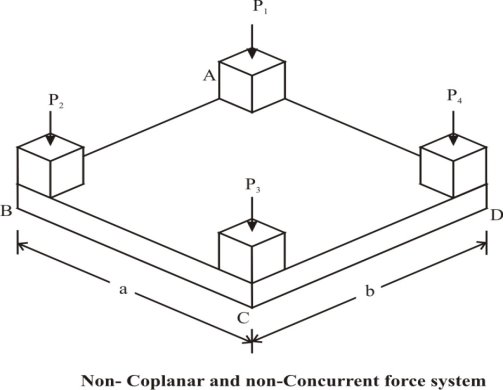
Fig.2.8 Force System Non-coplanar and non-concurrent force system The forces which do not lie in a single plane and do not pass through a single point are known as non-coplanar and non-concurrent forces. Example is the loads transferred through columns to the rectangular mat foundation as shown in Fig.2.10.
Fig. Non-coplanar non-concurrent force system |
Beam – It is horizontal structural member on which different types of loads can be supported. It takes load from floor or roof & transfers to column. The beam may be sometimes constructed in the inclined position for architectural point of view. Types of Beam: -
A beam which is just resting on the supports at the end without any connection is known as simply supported beam. It is generally used for vertical landing system.
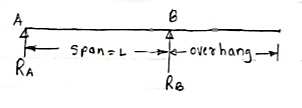
2. Overhanging Beam – A beam which is supported at the intermediate point other than ends is called as overhanging beam. Here portion of beam is extended beyond the support
(single overhanging beam)
b)
(doubly overhanging beam)
3. Cantilever Beam – A beam which is fixed at one end is called as cantilever beam
Here, there are three reactions components:
We can assume any direction for above components. 4. Continuous Beam:
A beam having more than two supports is called as continuous beam.
5. Compound Beam:
When two or more beams are joined together by using internal hinge; or when one beam rests over another beam by using internal roller, then such beam is called as compound beam.
Type of supports and reaction:
Types of loads on the Beam
Load acting at a single point on the beam is known as point load. Its unit is N or kN
2. Uniformly Distributed load (UDL) or Rectangular Load:
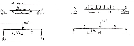
A load which is spread over the beam or part of the beam uniformly is known as UDL
Conversion of UDL or Rectangular load into point load = Intensity of UDL × distance = w. l. ------------- N
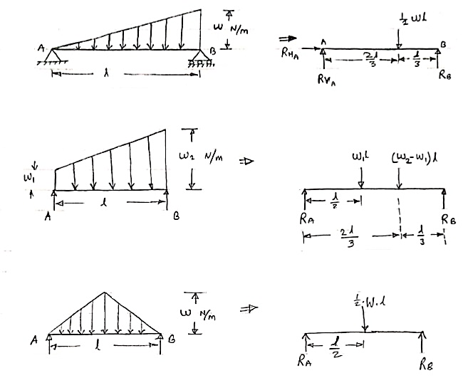
3. Uniformly varying load or Triangular load:
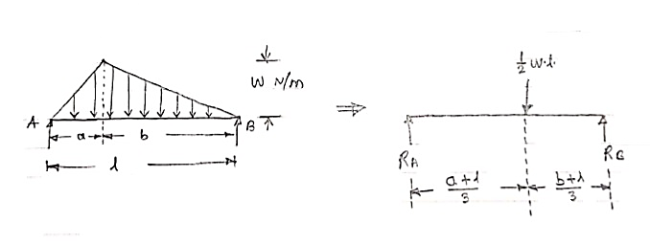
A load whose intensity is linearly varying between the two points on the beam is known as UVL. If an intensity of the load at one end is zero and at other ends is maximum then it is called as uniformly varying load or triangular load. Following figures shows different types of UVL
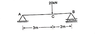
Example- Find the support reactions of given beam for loading as shown below.
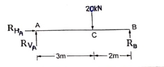
∑fx = 0 RHA = 0 ∑fxy = 0 RVA – 20 + RB = 0 RVA + RB = 20 ----- (1) Taking moments at A ∑MA = 0 (20 × 3) – (RB × 5) = 0 60 – 5RB
RB = 12 kN
RVA = 8 kN
|
References:
1. Engineering Mechanics: F. L. Singer
2. Engineering Mechanics: Timoshenko & Young
3. Engineering Mechanics: Bear & Johnston
4. Engineering Mechanics: I. H. Shames
5. Engineering Mechanics: A. Nelson


