UNIT - 4
Kinematics & Kinetics of Particles
Motion is one of the most common phenomena we come across in our daily lives. For example, a moving car, a kid running on the road or a fly moving in the air are all said to be in motion. So, in general terms, a body is said to be in motion if it changes its position with respect to a reference point and time. Depending upon the path taken by the particle the motion can be of different types like projectile motion, rectilinear motion, rotational motion, etc. For now, we will only focus on the rectilinear motion which is also known as linear motion.
When we require only one co-ordinate axis along with time to describe the motion of a particle it is said to be in linear motion or rectilinear motion. Some examples of linear motion are a parade of soldiers, a train moving along a straight line, and many more.
So now that we have learned about linear motion we will discuss two terms related to change in position. These are called – ‘Distance’ and ‘Displacement’.
Distance is defined as, The total path length covered during a journey While displacement is defined as, The path length from final position of the particle to the origin O. Consider the following figure:
|
Fig 1
We have an origin O, measurements to the right of O are taken as a positive while to the left are taken as negative. Suppose a person, who starts from origin O reaches point A,
Distance = OA
Displacement = OA
Now he turns and reaches point B,
Distance = OA + AB
Displacement = -OB
As we can see, displacement is negative since it is measured to the left of the origin. From the above example, we can infer that distance is always positive while displacement can either be positive or negative.
These terms are used to describe the rate of change of position. Speed is the rate of change of distance while velocity is the rate of change of displacement. Comparing from above as distance can never be negative so the speed is never negative while velocity can be both positive and negative. In mathematical terms, these are defined as follows:
Speed = Distance Travelled Time Taken
Velocity = (Final position–Initial position) Time Taken
Examples for Rectilinear Motion
Following are the rectilinear motion examples:
- The use of elevators in public places is an example of rectilinear motion.
- Gravitational forces acting on objects resulting in free fall is an example of rectilinear motion.
- Kids sliding down from a slide are a rectilinear motion.
- The motion of planes in the sky is a rectilinear motion.
Key Takeaways
1) Speed = Distance Travelled Time Taken
2) Velocity = (Final position–Initial position) Time Taken
3) First Equation of Motion : v=u + at
4) Second Equation of Motion : s = ut+1/2at2
5) Third Equation of Motion : v2=u2+2as
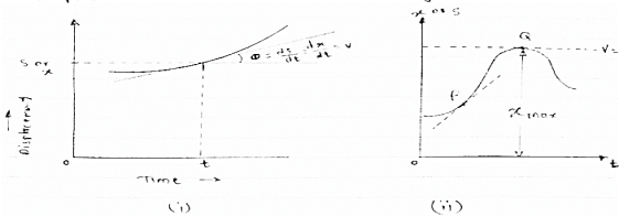
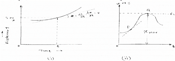
it is a graphical representation of displacement velocity acceleration with time. (1) Displacement - time curve : (x –t diagram) Fig 2
This diagram represents position of particle w.r.t to time here time is taken on x axis & displacement (s or x) is taken on y axis Slope x t diagram at any point represents the velocity at the instant ∴at any instant t (time) Velocity is given by v =ds/dt = dx/dt (2) Velocity time curve: [v - t diagram]
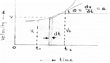
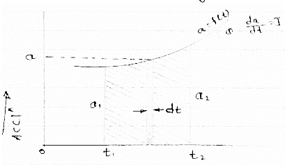
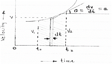
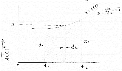
Fig 3 This diagram represents velocity of particle w.r.t. time here velocity is taken on y axis & time on x axis (a) The slop of v – t diagram represents acceleration at that instant ∴a= dv/dt (b)area under the curve (v –t curve)represent change in displacement (x or s)between two instant of time ∴let us select elementary trip between t1 & t2. ∴The area of strip da = v x dt Area bounded between t1 &t2 can be find out by integrating area of elementary strip. ∴da= v.dt ∴∫da =∫v.dt ∴ A = But v=dx/dt b ∴v.dt = dx ∴ A = ∴A = area between (t1 & t2 ) = x2 - x1 (2) Acceleration - time diagram (a –t curves): Fig 4 This representation acceleration of particle w.r.t time‘t’ acceleration is plotted on y axis & time is plotted on x axis. The slope of the curve representation jerks J = da/dt The area under a- t diagram between two instant of time (t1 & t2) represent change in velocity Let us consider an elementary strip ∴ Area of strip da= na.dt ∴ Total area a = But a= dv/dt∴ a. dt = dv ∴ a = ∴ Area a= v2 - v1 The position coordinate (x) is directly found out from the following moment equation (from a – t diagram) X1 =x0 + v0 t + mt Where, Xt= position of particle at time‘t’ X0 =initial position of particle V0 = initial velocity of particle Mt=moment of area under a - t diagram about the instant t. Velocity - displacement diagram(v -x)
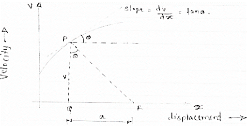
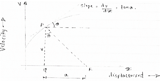
Fig 5 Here plot or graph of velocity (on y axis ) & displacement on (x axis) is drawn. If a normal is drawn to the tangent on curve the subnormal on x axis represents the acceleration Let pr is the normal drawn at p The subnormal =pq.tanθ =v.tanθ = v.dv/dx = a ∴ a = V ∴ Acceleration = velocity x slope of v- x diagram
|
Key takeaways
1) Motion curve is graphical representation of displacement velocity acceleration with time.
2) Acceleration = velocity x slope of v- x diagram
When a particle is freely thrown in the air along any direction other than vertical it follows it follows the parabolic path. The motion of a particle along this parabolic path is called as projectile motion.
i.e. when we project the particle in the space, its motion is a combination of horizontal & vertical motion. This motion is called as projectile Motion.
Wind Resistance, curvature & rotation of the earth affects the actual path.
But these parameters are neglected.
- The path Traced by projectile is called as Trajectory.”
- The motion of projectile in Horizontal direction is uniform motion.
- Ax = Horizontal component of acceleration = 0
- The acceleration in vertical direction is affected by gravity. Thus motion in y direction is considered as “Motion under gravity.”
:.  y = -
y = -
Basic Terms involved in the projectile Motion
1) Time of flight :- (t)
- The time by the projectile to move from point of projection to the point of target is called as “Time of flight.”
- It is the total time during which projectile remains in space.
2) “Horizontal Range” :- (R)
It is Horizontal distance from point of projection the point of target. OR It is Horizontal distance bet/n point of projection & point of landing.
3) Maximum Height :- (H) or (Hmax)
It is the vertical distance bet/n the point of projection and the point © where the vertical component of velocity is zero.
4) Angle of projection :(  )
)
- It is the angle made by velocity with the Horizontal.
- If velocity is directed up the horizontal, then it is called as angle of elevation.
-If the velocity is directed down the Horizontal, then it is called as angle of depression.
5) Trajectory:-
It is the path traced by a projectile during its motion. It is parabolic in nature.
Projectile on Horizontal plane
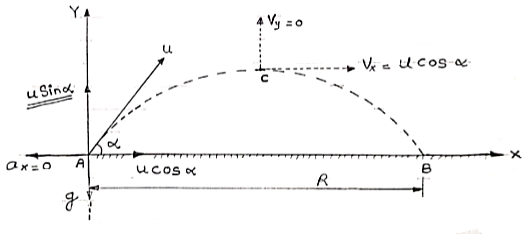
Consider a projectile projected from point A with
u= initial velocity of projection &
 = Angle of projection.
Let t = total time of flight.
Thus projectile will land at point b after time ‘t’ Both point A& B are Qn H.P
Diagram
|
Fig 6
As the air resistance is neglected, the motion in X-direction is uniform motion & y dirn motion is Motion under Gravity”. a) Time of flight (t) t 2 u sin b) Horizontal Range (R) R = u2. Sin2 c) Maximum Range (R max) For maximum Range angle of projection must be 45 R max = u2/ d) Maximum Height H = u2. Sin2
|
Derivation of path Equation
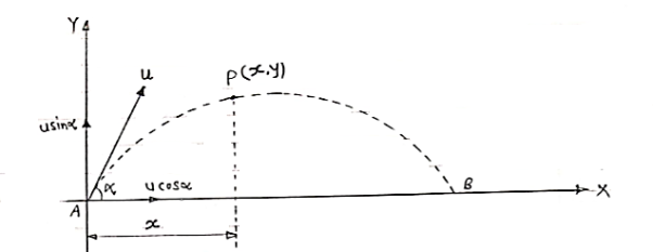
[Equation of Trajectory] Vx= u cos Vy = u sin
Fig 7 Consider a particle projected from A with initial velocity ‘u’ & angle of projection ‘ Let after time‘t’ the particle has reached at point p (x, y). Consider the motion of projectile in X dirn (VM):- [ A S= velocity * time X = u cos :. t1 = X/ u cos :. t1 = X/ u cos Consider the motion of projectile in y dir/n (m. U.G) [ A :. Sy= uyt1- ½ Y = u sin From equation (1), put the value of time t1 :. y = usin :. y = X. tan :. y X. tan
|
Eqn of Trajectory
Projectile on Inclined plane
Fig 8 Let projectile is projected from point A. let
Now let us select X axis along the inclined plane and y –axis perpendicular to the inclined plane. :. X component of velocity = u cos :. Y - ----- -------------------- u sin Similarly for gravitation According ‘g’ X component = g sin y component = g cos
a) Time of flight (t) b) Range along the plane (R) t= 2u. sin
c) Maximum Range (Rmax) d)Max. Height (lar to plane) Rmax = u2/g (1+sin
*Special cases of projectile* *projectile projected with Horizontal velocity:-*
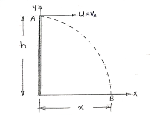
Consider motion A (V.M) X = u*t Consider Motion (y- motion) From A S = ut + ½ gt2 h= 0 + ½gt2 :. t= :. Horizontal distance, = X = u Y = x tanx - gx2/u2 cos 2 But :. –h = -y = 0 - gx2/2u2 :. h = gx2 / 2u2
*for given values of u, two angle gives us the same Range.
Key takeaway 1) Time of flight (t) t = 2 u sin 2) Horizontal Range (R) R = u2. Sin2 3) Maximum Range (R max) For maximum Range angle of projection must be 45 R max = u2/ 4) Maximum Height H = u2. Sin2 |
When a particle moves along a curved path, it is sometimes convenient to describe its motion using coordinates other than Cartesian. When the path of motion is known, normal (n) and tangential (t) coordinates are often used.
|
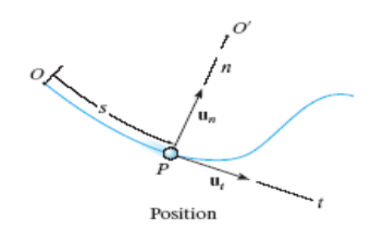
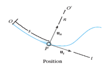
Fig 10 position of n-t component
In the n-t coordinate system, the origin is located on the particle (the origin moves with the particle). The t-axis is tangent to the path (curve) at the instant considered, positive in the direction of the particle’s motion. The n-axis is perpendicular to the t-axis with the positive direction toward the center of curvature of the curve.
The positive n and t directions are defined by the unit vectors un and ut, respectively. The center of curvature, O’, always lies on the concave side of the curve
|
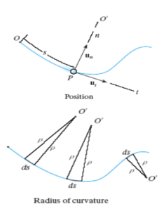
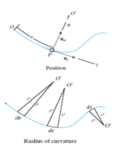
Fig 11 Radius of curvature
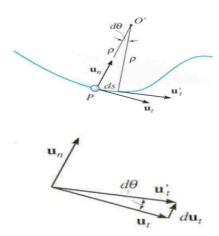
The radius of curvature, r, is defined as the perpendicular distance from the curve to the center of curvature at that point. The position of the particle at any instant is defined by the distance, s, along the curve from a fixed reference point.
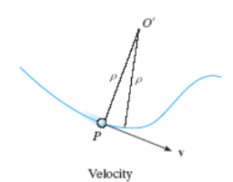
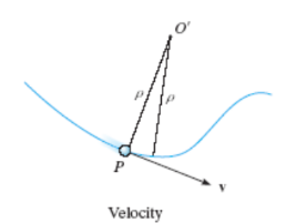
The velocity vector is always tangent to the path of motion (t-direction). The magnitude is determined by taking the time derivative of the path function, s(t)
|
Fig 12 velocity
v = vut Where
v = s = ds/dt
Here v defines the magnitude of the velocity (speed) and ut defines the direction of the velocity vector.
Acceleration is the time rate of change of velocity:
a = dv/dt
= d (vut)/dt
= vut + vut
|
Fig 13
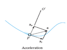
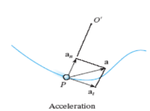
After mathematical manipulation, the acceleration vector can be expressed as: a = vut + (v2 /ρ)un = atut + anun There are two components to the acceleration vector: a = atut + anun
Fig 14 Acceleration • The tangential component is tangent to the curve and in the direction of increasing or decreasing velocity. at = v or at ds = v dv • The normal or centripetal component is always directed toward the center of curvature of the curve an = v 2 /ρ • The magnitude of the acceleration vector is a = [(at) 2 + (an) 2] 0.5
|
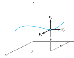
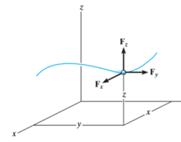
Kinetics of particle in rectangular coordinate When a particle is in motion and the inertial frame of reference is an x, y, z coordinate system, the forces acting on the particle and its acceleration is given in terms of their i, j, k components
And
Fig 15 Applying equation of motion
In scalar form,
Kinetics of particle in cylindrical coordinate
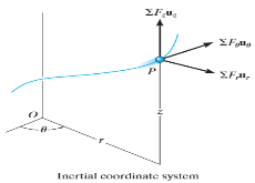
Fig 16 Inertial coordinate system When all the forces acting and accelerations of a particle are resolved into cylindrical components, the unit vectors in the r, The forces acting on the particle and its acceleration is given by
And
Applying equation of motion
In Scalar form,
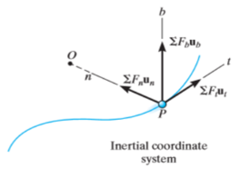
Kinetics of particle in terms of path variables When a particle is in motion along a curved path which is known, then equation of motion for the particle is written in the tangential (t), normal (n), and bi normal (b) directions. The direction of t, n and b coordinates is given by the unit vectors
Fig 17 Here, there will be no motion in bi normal direction as the particle moves along the fixed known path, but force may act in bi normal direction. The force and acceleration can be given as,
And,
Hence, applying equation of motion,
In scalar form,
As we know, And This is the reason why, |
Reference:
1. Engineering Mechanics by S. P. Timoshenko and D. H. Young, McGraw- Hill publication
2. Engineering Mechanics by J. L. Meriam and Craige John Willey
3. Engineering Mechanics by A. P. Boresi and R. J. Schmidt, Brooks/Cole Publication
UNIT - 4
Kinematics & Kinetics of Particles
Motion is one of the most common phenomena we come across in our daily lives. For example, a moving car, a kid running on the road or a fly moving in the air are all said to be in motion. So, in general terms, a body is said to be in motion if it changes its position with respect to a reference point and time. Depending upon the path taken by the particle the motion can be of different types like projectile motion, rectilinear motion, rotational motion, etc. For now, we will only focus on the rectilinear motion which is also known as linear motion.
When we require only one co-ordinate axis along with time to describe the motion of a particle it is said to be in linear motion or rectilinear motion. Some examples of linear motion are a parade of soldiers, a train moving along a straight line, and many more.
So now that we have learned about linear motion we will discuss two terms related to change in position. These are called – ‘Distance’ and ‘Displacement’.
Distance is defined as, The total path length covered during a journey While displacement is defined as, The path length from final position of the particle to the origin O. Consider the following figure:
|
Fig 1
We have an origin O, measurements to the right of O are taken as a positive while to the left are taken as negative. Suppose a person, who starts from origin O reaches point A,
Distance = OA
Displacement = OA
Now he turns and reaches point B,
Distance = OA + AB
Displacement = -OB
As we can see, displacement is negative since it is measured to the left of the origin. From the above example, we can infer that distance is always positive while displacement can either be positive or negative.
These terms are used to describe the rate of change of position. Speed is the rate of change of distance while velocity is the rate of change of displacement. Comparing from above as distance can never be negative so the speed is never negative while velocity can be both positive and negative. In mathematical terms, these are defined as follows:
Speed = Distance Travelled Time Taken
Velocity = (Final position–Initial position) Time Taken
Examples for Rectilinear Motion
Following are the rectilinear motion examples:
- The use of elevators in public places is an example of rectilinear motion.
- Gravitational forces acting on objects resulting in free fall is an example of rectilinear motion.
- Kids sliding down from a slide are a rectilinear motion.
- The motion of planes in the sky is a rectilinear motion.
Key Takeaways
1) Speed = Distance Travelled Time Taken
2) Velocity = (Final position–Initial position) Time Taken
3) First Equation of Motion : v=u + at
4) Second Equation of Motion : s = ut+1/2at2
5) Third Equation of Motion : v2=u2+2as
it is a graphical representation of displacement velocity acceleration with time. (1) Displacement - time curve : (x –t diagram) Fig 2
This diagram represents position of particle w.r.t to time here time is taken on x axis & displacement (s or x) is taken on y axis Slope x t diagram at any point represents the velocity at the instant ∴at any instant t (time) Velocity is given by v =ds/dt = dx/dt (2) Velocity time curve: [v - t diagram]
Fig 3 This diagram represents velocity of particle w.r.t. time here velocity is taken on y axis & time on x axis (a) The slop of v – t diagram represents acceleration at that instant ∴a= dv/dt (b)area under the curve (v –t curve)represent change in displacement (x or s)between two instant of time ∴let us select elementary trip between t1 & t2. ∴The area of strip da = v x dt Area bounded between t1 &t2 can be find out by integrating area of elementary strip. ∴da= v.dt ∴∫da =∫v.dt ∴ A = But v=dx/dt b ∴v.dt = dx ∴ A = ∴A = area between (t1 & t2 ) = x2 - x1 (2) Acceleration - time diagram (a –t curves): Fig 4 This representation acceleration of particle w.r.t time‘t’ acceleration is plotted on y axis & time is plotted on x axis. The slope of the curve representation jerks J = da/dt The area under a- t diagram between two instant of time (t1 & t2) represent change in velocity Let us consider an elementary strip ∴ Area of strip da= na.dt ∴ Total area a = But a= dv/dt∴ a. dt = dv ∴ a = ∴ Area a= v2 - v1 The position coordinate (x) is directly found out from the following moment equation (from a – t diagram) X1 =x0 + v0 t + mt Where, Xt= position of particle at time‘t’ X0 =initial position of particle V0 = initial velocity of particle Mt=moment of area under a - t diagram about the instant t. Velocity - displacement diagram(v -x)
Fig 5 Here plot or graph of velocity (on y axis ) & displacement on (x axis) is drawn. If a normal is drawn to the tangent on curve the subnormal on x axis represents the acceleration Let pr is the normal drawn at p The subnormal =pq.tanθ =v.tanθ = v.dv/dx = a ∴ a = V ∴ Acceleration = velocity x slope of v- x diagram
|
Key takeaways
1) Motion curve is graphical representation of displacement velocity acceleration with time.
2) Acceleration = velocity x slope of v- x diagram
When a particle is freely thrown in the air along any direction other than vertical it follows it follows the parabolic path. The motion of a particle along this parabolic path is called as projectile motion.
i.e. when we project the particle in the space, its motion is a combination of horizontal & vertical motion. This motion is called as projectile Motion.
Wind Resistance, curvature & rotation of the earth affects the actual path.
But these parameters are neglected.
- The path Traced by projectile is called as Trajectory.”
- The motion of projectile in Horizontal direction is uniform motion.
- Ax = Horizontal component of acceleration = 0
- The acceleration in vertical direction is affected by gravity. Thus motion in y direction is considered as “Motion under gravity.”
:.  y = -
y = -
Basic Terms involved in the projectile Motion
1) Time of flight :- (t)
- The time by the projectile to move from point of projection to the point of target is called as “Time of flight.”
- It is the total time during which projectile remains in space.
2) “Horizontal Range” :- (R)
It is Horizontal distance from point of projection the point of target. OR It is Horizontal distance bet/n point of projection & point of landing.
3) Maximum Height :- (H) or (Hmax)
It is the vertical distance bet/n the point of projection and the point © where the vertical component of velocity is zero.
4) Angle of projection :(  )
)
- It is the angle made by velocity with the Horizontal.
- If velocity is directed up the horizontal, then it is called as angle of elevation.
-If the velocity is directed down the Horizontal, then it is called as angle of depression.
5) Trajectory:-
It is the path traced by a projectile during its motion. It is parabolic in nature.
Projectile on Horizontal plane
Consider a projectile projected from point A with
u= initial velocity of projection &
 = Angle of projection.
Let t = total time of flight.
Thus projectile will land at point b after time ‘t’ Both point A& B are Qn H.P
Diagram
|
Fig 6
As the air resistance is neglected, the motion in X-direction is uniform motion & y dirn motion is Motion under Gravity”. a) Time of flight (t) t 2 u sin b) Horizontal Range (R) R = u2. Sin2 c) Maximum Range (R max) For maximum Range angle of projection must be 45 R max = u2/ d) Maximum Height H = u2. Sin2
|
Derivation of path Equation
[Equation of Trajectory] Vx= u cos Vy = u sin
Fig 7 Consider a particle projected from A with initial velocity ‘u’ & angle of projection ‘ Let after time‘t’ the particle has reached at point p (x, y). Consider the motion of projectile in X dirn (VM):- [ A S= velocity * time X = u cos :. t1 = X/ u cos :. t1 = X/ u cos Consider the motion of projectile in y dir/n (m. U.G) [ A :. Sy= uyt1- ½ Y = u sin From equation (1), put the value of time t1 :. y = usin :. y = X. tan :. y X. tan
|
Eqn of Trajectory
Projectile on Inclined plane
Fig 8 Let projectile is projected from point A. let
Now let us select X axis along the inclined plane and y –axis perpendicular to the inclined plane. :. X component of velocity = u cos :. Y - ----- -------------------- u sin Similarly for gravitation According ‘g’ X component = g sin y component = g cos
a) Time of flight (t) b) Range along the plane (R) t= 2u. sin
c) Maximum Range (Rmax) d)Max. Height (lar to plane) Rmax = u2/g (1+sin
*Special cases of projectile* *projectile projected with Horizontal velocity:-*
Consider motion A (V.M) X = u*t Consider Motion (y- motion) From A S = ut + ½ gt2 h= 0 + ½gt2 :. t= :. Horizontal distance, = X = u Y = x tanx - gx2/u2 cos 2 But :. –h = -y = 0 - gx2/2u2 :. h = gx2 / 2u2
*for given values of u, two angle gives us the same Range.
Key takeaway 1) Time of flight (t) t = 2 u sin 2) Horizontal Range (R) R = u2. Sin2 3) Maximum Range (R max) For maximum Range angle of projection must be 45 R max = u2/ 4) Maximum Height H = u2. Sin2 |
When a particle moves along a curved path, it is sometimes convenient to describe its motion using coordinates other than Cartesian. When the path of motion is known, normal (n) and tangential (t) coordinates are often used.
|
Fig 10 position of n-t component
In the n-t coordinate system, the origin is located on the particle (the origin moves with the particle). The t-axis is tangent to the path (curve) at the instant considered, positive in the direction of the particle’s motion. The n-axis is perpendicular to the t-axis with the positive direction toward the center of curvature of the curve.
The positive n and t directions are defined by the unit vectors un and ut, respectively. The center of curvature, O’, always lies on the concave side of the curve
|
Fig 11 Radius of curvature
The radius of curvature, r, is defined as the perpendicular distance from the curve to the center of curvature at that point. The position of the particle at any instant is defined by the distance, s, along the curve from a fixed reference point.
The velocity vector is always tangent to the path of motion (t-direction). The magnitude is determined by taking the time derivative of the path function, s(t)
|
Fig 12 velocity
v = vut Where
v = s = ds/dt
Here v defines the magnitude of the velocity (speed) and ut defines the direction of the velocity vector.
Acceleration is the time rate of change of velocity:
a = dv/dt
= d (vut)/dt
= vut + vut
|
Fig 13
After mathematical manipulation, the acceleration vector can be expressed as: a = vut + (v2 /ρ)un = atut + anun There are two components to the acceleration vector: a = atut + anun
Fig 14 Acceleration • The tangential component is tangent to the curve and in the direction of increasing or decreasing velocity. at = v or at ds = v dv • The normal or centripetal component is always directed toward the center of curvature of the curve an = v 2 /ρ • The magnitude of the acceleration vector is a = [(at) 2 + (an) 2] 0.5
|
Kinetics of particle in rectangular coordinate When a particle is in motion and the inertial frame of reference is an x, y, z coordinate system, the forces acting on the particle and its acceleration is given in terms of their i, j, k components
And
Fig 15 Applying equation of motion
In scalar form,
Kinetics of particle in cylindrical coordinate
Fig 16 Inertial coordinate system When all the forces acting and accelerations of a particle are resolved into cylindrical components, the unit vectors in the r, The forces acting on the particle and its acceleration is given by
And
Applying equation of motion
In Scalar form,
Kinetics of particle in terms of path variables When a particle is in motion along a curved path which is known, then equation of motion for the particle is written in the tangential (t), normal (n), and bi normal (b) directions. The direction of t, n and b coordinates is given by the unit vectors
Fig 17 Here, there will be no motion in bi normal direction as the particle moves along the fixed known path, but force may act in bi normal direction. The force and acceleration can be given as,
And,
Hence, applying equation of motion,
In scalar form,
As we know, And This is the reason why, |
Reference:
1. Engineering Mechanics by S. P. Timoshenko and D. H. Young, McGraw- Hill publication
2. Engineering Mechanics by J. L. Meriam and Craige John Willey
3. Engineering Mechanics by A. P. Boresi and R. J. Schmidt, Brooks/Cole Publication

