Unit 10
Refrigeration & Air Conditioning
Content:
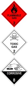
A refrigerant is a substance used in a heat cycle to transfer heat from one area, and remove it to another. Usually a gas at room temperature. Found in pretty much everything that cools, and sometimes in things that heat, most commonly air conditioners, fridges, freezers, and vehicle air conditioners. Traditionally, fluorocarbons, especially chlorofluorocarbons (CFC’s), were used as refrigerants, but they are being phased out because of their ozone depleting effects. Other common refrigerants used in various applications are ammonia, sulphur dioxide, and non-halogenated hydrocarbons such as propane. Most refrigerants found in end of life devices are ozone depleting and global warming inducing compounds.
Common refrigerants include:
R12
- 10,900 times more powerful a greenhouse gas than carbon dioxide
- An ozone depleting CFC
- Mainly found in fridges and freezers
- Found in approximately 65% of fridges/freezers at transfer stations and scrap yards
- Not found in fridges or freezers manufactured or imported after 1995 as it was banned under the Montreal protocol. Illegal to buy or sell.
- Replaced by R134a in 1995.
- Venting from the average fridge or freezer is the equivalent of 6 months of carbon emissions from the average home
R134a
- 1,430 times more powerful a greenhouse gas than carbon dioxide
- No harmful effects on the ozone layer
- Mainly found in fridges and freezers
- Found in approximately 30% of fridges/freezers at transfer stations and scrap yards
- Venting from the average fridge or freezer is the equivalent of 1 month of emissions from the average home.
R22
- 1,810 times more powerful a greenhouse gas than carbon dioxide
- An ozone depleting HCFC (a less potent type of CFC)
- Mainly found in ‘window rattler’ air conditioners
- Venting from the average air conditioner is the equivalent of 2 months of carbon emissions from the average home
R410a
- 2,088 times more powerful a greenhouse gas than carbon dioxide
- No harmful effects on the ozone layer
- Mainly found in split system air conditioners
- Venting from the average air conditioner is the equivalent of 2 months of carbon emissions from the average home
R290, R600, R600a, R601, R601a
- A group of hydrocarbon refrigerants including butane, isobutene, pentane, and isopentane
- Extremely flammable
- 2-4 times more powerful a greenhouse gas than carbon dioxide. Legal to dump in atmosphere.
- No harmful effects on the ozone layer
- Mainly found in newer fridges and freezers, less than 5% of total units.
R717
- Anhydrous ammonia
- Extremely flammable
- No global warming potential. Legal to dump in atmosphere
- Presents the biggest OHS issues of all units when decommissioning. It is corrosive and toxic – exposure can cause death when inhaled at concentrations as low as 25 parts per million.
- No harmful effects on the ozone layer
- Mainly found in three way fridges and freezers i.e. absorption units, less than 5% of total units.
There are hundreds of refrigerants out there those listed above are the ones you are most likely to come across at a transfer station or recycling centre.
The average fridge or freezer usually contains 100-500 grams refrigerant, with an air conditioner usually carrying 1-2kg of refrigerant.
Vapour compression system: Vapour-compression refrigeration, in which the refrigerant undergoes phase changes, is one of the many refrigeration cycles and is the most widely used method for air-conditioning of buildings and automobiles. It is also used in domestic and commercial refrigerators, large-scale warehouses for chilled or frozen storage of foods and meats, refrigerated trucks and railroad cars, and a host of other commercial and industrial services. Oil refineries, petrochemical and chemical processing plants, and natural gas processing plants are among the many types of industrial plants that often utilize large vapour-compression refrigeration systems.
Working of Vapour Compression Refrigeration System:
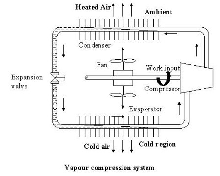
As shown in the figure the basic system consists of an evaporator, compressor, condenser and an expansion valve.
The refrigeration effect is obtained in the cold region as heat is extracted by the vaporization of refrigerant in the evaporator. The refrigerant vapour from the evaporator is compressed in the compressor to a high pressure at which its saturation temperature is greater than the ambient or any other heat sink. Hence when the high pressure, high-temperature refrigerant flows through the condenser, condensation of the vapour into liquid takes place by heat rejection to the heat sink. To complete the cycle, the high-pressure liquid is made to flow through an expansion valve. In the expansion valve the pressure and temperature of the refrigerant decrease. This low pressure and low-temperature refrigerant vapour evaporates in the evaporator taking heat from the cold region. It should be observed that the system operates on a closed cycle. The system requires input in the form of mechanical work. It extracts heat from a cold space and rejects heat to a high-temperature heat sink.
Vapour Compression Cycle -Working Diagram
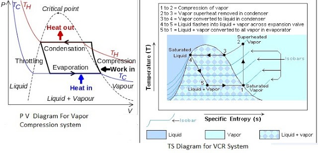 PV And TS Diagram for Vapour Compression System
Most of the modern refrigerators work on this cycle, in its simplest form, there are four fundamental operations required to complete one cycle.
(a) Compression
(b) Condensation
(c) Expansion
(d) Vaporization
a) Compression
The low-pressure Vapour in the dry state is drawn from the evaporator during the suction stroke of the compressor. During compression Stroke, the pressure and temperature increase until vapour temperature is greater than the temperature of condenser cooling medium (air or water)
At point 1 in the diagram, the circulating refrigerant enters the compressor as a saturated vapour. From point 1 to point 2, the vapour is isentropically compressed (i.e., compressed at constant entropy) and exits the compressor as a superheated vapour.
b) Condensation
When the high-pressure refrigerant vapour enters the condenser, heat flows from the condenser to the cooling medium thus allowing the vaporized refrigerant to return to the liquid state.
From point 2 to point 3, the vapour travels through part of the condenser which removes the superheat by cooling the vapour. Between point 3 and point 4, the vapour travels through the remainder of the condenser and is condensed into a saturated liquid. The condensation process occurs at essentially constant pressure.
c) Expansion
After condenser the liquid refrigerant is stored in the liquid receiver until needed. From the receiver it passes through an expansion valve where the pressure is reduced sufficiently to allow the vaporization of liquid at a low temperature of about -10°C.
Between points 4 and 5, the saturated liquid refrigerant passes through the expansion valve and undergoes an abrupt decrease of pressure. That process results in the adiabatic flash evaporation and auto-refrigeration of a portion of the liquid (typically, less than half of the liquid flashes).
d) Vaporization
The low-pressure refrigerant vapour after expansion in the expansion valve enters the evaporator or refrigerated space where a considerable amount of heat IS absorbed by it and refrigeration is furnished.
Between points 5 and 1, the cold and partially vaporized refrigerant travels through the coil or tubes in the evaporator where it is vaporized by the warm air (from the space being refrigerated) that a fan circulates across the coil or tubes in the evaporator. The resulting refrigerant vapour returns to the compressor inlet at point 1 to complete the thermodynamic cycle.
The power utilized in vapour compression system is high grade energy i.e., electric power for running the compressor motor. In absorption refrigeration system, however, heat is directly utilized as source of energy. Of course, it may be preferable to utilize heat as such as it avoids undergoing through the various energy transformations required in the generation of electrical energy from heat energy.
It may be recalled that in the compression system the vapour was compressed by undergoing a great change in volume during the compression process. Accordingly, the major part of the power was consumed in the process. If means were available for rising this pressure of the refrigerant without appreciably altering its volume, the work requirements will be enormously reduced (by about 95% or so).
This may possibly be done by dissolving the refrigerant in some absorbent and supplying the heat to the solution for compression purposes. The absorption cycle achieves this objective by placing the refrigerant in solution before the so called compression process and by removing from the solution immediately after the process. The absorption of the vapour is governed by Raoult’s law.
The basic difference between vapour compression and vapour absorption cycles will thus be to replace the compressor of the vapour compression cycle by a set of equipment which fulfils the objective discussed above. The other important element i.e., condenser, expansion device and evaporator will exist in both systems.
Simple Vapour Absorption Cycle:
Illustrates the simplest scheme of equipment required for the replacement of the compressor.
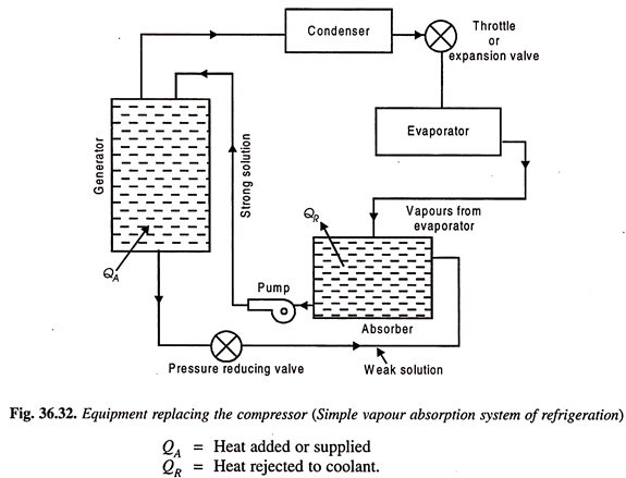
The most commonly used fluids in the absorption system are water as absorbent and ammonia as refrigerant. The vapour from the evaporator is allowed to be mixed and absorbed in the absorber. The heat of absorption generated in the process is rejected from the absorber to the circulating cold water in a heat exchanger dipped in the solution contained in the absorber.
The strong aqua-ammonia solution from the absorber is pumped up to the condenser pressure and fed to the generator which is the main energy consuming element of the system. Heat is supplied to the generator. The boiling point of refrigerant NH3, is lower than that of the absorbing liquid H2O, hence the vapours leaving the generator are predominantly those of refrigerant.
These vapours then pass on to the condenser. The liquid refrigerant from the condenser, then, passes through an expansion valve or throttle valve to the evaporator where it absorbs heat from the substances or bodies to be refrigerated. Liquid refrigerant is then evaporated and the vapours enter the absorber completing the cycle.
The weak aqua-ammonia solution in the generator left due to separation of refrigerant vapour is drained back to the absorber for repeating the cycle.
The weak aqua-ammonia solution leaving the generator is at high pressure and the pressure in the absorber is the evaporator pressure which is less than the generator or condenser pressure, and hence a pressure reducing valve is provided in the weak solution line to the absorber. The energy requirements of the system are at the generator and at the pump as compared to those at compressor in the vapour compression system. Since the volume of liquid handled by the pump is too small, the power required here is almost negligible as compared to that by the generator.
Practical Absorption Refrigeration Cycle:
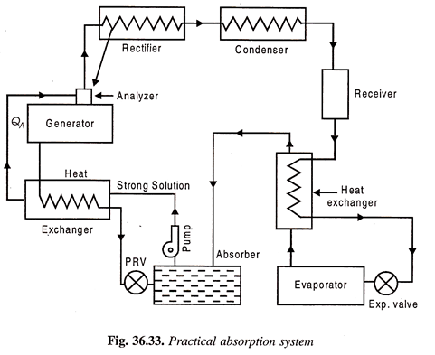
The replacement of the compressor by the simple arrangement of Fig. 36.33 is not very economical in practice. In order to make improvements certain additional auxiliary items are provided in the system. They include analyser, a rectifier, and two heat exchangers. The practical absorption cycles as developed after incorporating these auxiliaries is shown in Fig
(a) Analyser:
The ammonia vapours leaving the generator may contain certain moisture, and therefore it should be freed from any trace of water vapour before passing on to the condenser and then to the expansion valve, otherwise the water vapour is likely to freeze in the small valve passage and choke the flow. The function of the analyser is to remove the moisture as far as possible. It is an open types of cooler and forms an integral part of the generator, mounted on its top. Both the strong aqua-ammonia solution from the absorber and the condensate removed in rectifier are introduced from the top and flow downwards. The hot rising vapour of ammonia therefore comes in contact with the same and gets cooled. Thus, most of the water vapour is condensed and drips back into the generator. This helps in salvaging a certain portion of heat in outgoing vapour which would otherwise have been rejected out through the condenser.
(b) Rectifier:
It is a closed type of cooler and is actually a miniature condenser where any traces of water vapour left in the ammonia vapour, are removed by condensation the cooling is achieved by circulating water as is done in an ordinary condenser. The condensed aqua is drained back to the generator through the analyser.
(c) Heat Exchangers:
Two heat exchangers are provided to internally exchange heat from the higher temperature fluid to the lower temperature fluid so that one is cooled and the other is heated. One heat exchanger is provided between liquid receiver and evaporator so that the liquid is sub-cooled and vapour is heated up. Another heat exchanger is located between generator and absorber so that the strong aqua is heated up before going on to the analyser and weak aqua is cooled before entering the absorber.
Performance of Vapour Absorption System:
Maximum coefficient of performance of heat operated vapour absorption system:
We know that refrigerant vapours are liberated from the strong solution when heated in a generator. This type of the machine or system is called a heat operated machine. Let Th be the temperature at which heat is supplied to the strong solution.
Tk is the temperature at which heat is rejected to atmosphere; To is the temperature of the body to be refrigerated. Thermal efficiency of the engine is given by-
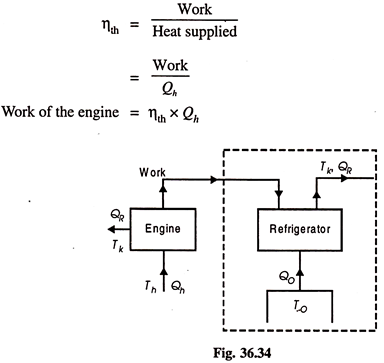
This work, it is assumed, is used for refrigeration system. For refrigeration system, to is the temperature at which heat is given to refrigerant (actually this is the heat abstracted from the body to be refrigerated) and the heat is rejected the atmosphere at Tk temperature.
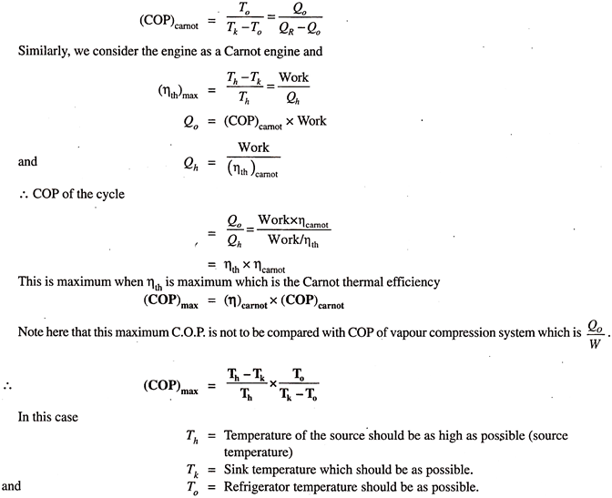
To get the maximum COP, we have to consider the Carnot reversed engine.
Single-Effect and Double-Effect Cycles:
In vapour absorption refrigeration system, the temperature of the heat source plays an important role. The heat given by the source may be used in one single stage or in more than one stage. Accordingly, the system is called as single stage or single effect cycle of operation and if the heat is supplied in two stages then the system is called two stage or double effect cycle of operation.
It is found that when the temperature of the heat source is up to 105°C, the heat is utilized in a single stage and the cycle is a single effect cycle. When the temperature of heat source is greater than 105°C, then generally the heat is utilized in two stages and the system becomes a double-effect cycle.
1. Single Effect Cycle:
A simple and practical absorption system using ammonia as refrigerant and water as absorbent described in the previous articles is an example of single-effect cycle system for vapour absorption refrigeration system.
2. Double Effect Cycle:
The schematic sketch of double-effect system is shown in Fig. 36.35. Vapours of refrigerants are generated in two stages as shown. For this purpose, two heat exchangers are used. Figure 36.35 for double-effect system is self-explanatory.
The common type of domestic refrigerator has a cabinet shaped with compressor, the condenser and receiver fitted in their basement. The expansion valve and evaporator coils are exposed in the storage cabinet with the piping’s, carrying liquid refrigerant passing through the body.
Generally, methylene chloride, Freon-12, and Freon-11 are used as the refrigerants.
Refrigeration is not only provided with double-walled cabinet packed with materials having high thermal insulation such as fiberglass, cork or expanded rubber but also all around the inside of door flap soft rubber seal is used which makes the cabinet airtight.
Also, the door is provided with automatic closing mechanism door hinges are provided in such a way that door flap when left in open position automatically comes to closing position due to gravity and as it approaches closing position it is attracted by the magnetic strip fitted behind the sealing rubber ring and thus the door is closed with snap action.
All this is done to prevent leakage of atmospheric heat inside the refrigerator. The main precaution to be taken is that very hot things should not be put in the refrigerator if it is done it will quickly evaporate the refrigerant in evaporator coils producing a large vapour pressure increasing the duty of the compressor. It may damage the motor, which is short-time rated.
Parts of refrigerator:
The refrigerator can be categorized into two categories: internal and external.
The internal parts are ones that carry out actual working of the refrigerator. Some of the internal parts are located at the back of the refrigerator, and some inside the main compartment of the refrigerator.
1) Refrigerant:
The refrigerant flows through all the internal parts of the refrigerator. It is the refrigerant that carries out the cooling effect in the evaporator. It absorbs the heat from the substance to be cooled in the evaporator (chillier or freezer) and throws it to the atmosphere via condenser. The refrigerant keeps on recirculating through all the internal parts of the refrigerator in cycle.
2) Compressor: The compressor is located at the back of the refrigerator and in the bottom area. The compressor sucks the refrigerant from the evaporator and discharges it at high pressure and temperature. The compressor is driven by the electric motor and it is the major power consuming device of the refrigerator.
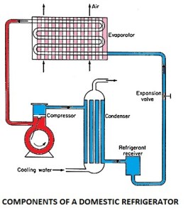
3) Condenser: The condenser is the thin coil of copper tubing located at the back of the refrigerator. The refrigerant from the compressor enters the condenser where it is cooled by the atmospheric air thus losing heat absorbed by it in the evaporator and the compressor. To increase the heat transfer rate of the condenser, it is finned externally.
4) Expansive valve or the capillary: The refrigerant leaving the condenser enters the expansion devise, which is the capillary tube in case of the domestic refrigerators. The capillary is the thin copper tubing made up of number of turns of the copper coil. When the refrigerant is passed through the capillary its pressure and temperature drops down suddenly.
5) Evaporator or chiller or freezer: The refrigerant at very low pressure and temperature enters the evaporator or the freezer. The evaporator is the heat exchanger made up of several turns of copper or aluminium tubing. In domestic refrigerators the plate types of evaporator is used as shown in the figure above. The refrigerant absorbs the heat from the substance to be cooled in the evaporator, gets evaporated and it then sucked by the compressor. This cycle keeps on repeating.
6) Temperature control device or thermostat: To control the temperature inside the refrigerator there is the thermostat, whose sensor is connected to the evaporator. The thermostat setting can be done by the round knob inside the refrigerator compartment. When the set temperature is reached inside the refrigerator the thermostat stops the electric supply to the compressor and compressor stops and when the temperature falls below certain level it restarts the supply to the compressor.
7) Defrost system: The defrost system of the refrigerator helps removing the excess ice from the surface of the evaporator. The defrost system can be operated manually by the thermostat button or there is automatic system comprising of the electric heater and the timer. Those were some internal components of the domestic refrigerator; now let us see the external parts.
External visible Parts of the Refrigerator
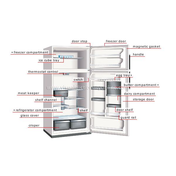
The external parts of the compressor are the parts that are visible externally and used for the various purposes. The figure below shows the common parts of the domestic refrigerator and some them are described below:
1) Freezer compartment: The food items that are to be kept at the freezing temperature are stored in the freezer compartment. The temperature here is below zero degrees Celsius so the water and many other fluids freeze in this compartment. If you want to make ice cream, ice, freeze the food etc. they have to be kept in the freezer compartment.
3) Thermostat control: The thermostat control comprises of the round knob with the temperature scale that help setting the required temperature inside the refrigerator. Proper setting of the thermostat as per the requirements can help saving lots of refrigerator electricity bills.
4) Refrigerator compartment: The refrigerator compartment is the biggest part of the refrigerator. Here all the food items that are to be maintained at temperature above zero degree Celsius but in cooled condition are kept. The refrigerator compartment can be divided into number of smaller shelves like meat keeper, and others as per the requirement.
4) Crisper: The highest temperature in the refrigerator compartment is maintained in the crisper. Here one can keep the food items that can remain fresh even at the medium temperature like fruits, vegetables, etc.
5) Refrigerator door compartment: There are number of smaller subsections in the refrigerator main door compartment. Some of these are egg compartment, butter, dairy, etc.
6) Switch: This is the small button that operates the small light inside the refrigerator. As soon the door of the refrigerator opens, this switch supplies electricity to the bulb and it starts, while when the door is closed the light from the bulb stops. This helps in starting the internal bulb only when required.
Working Principle of domestic refrigerator:
The refrigerator works on the vapour compression refrigeration cycle. The refrigerant vapour is first compressed in the compressor. The compressor is a special one known as the hermetic compressor. In this unit, the compressor is sealed casing along with an electrical motor to run. This sealing prevents leakage of refrigerant and lubrication oil. The pressure and temperature of the refrigerant increases after compression and is subsequently condensed in a condenser. In the condenser, the refrigerant rejects heat to a coolant and cools down and finally gets condensed. The condensate is then allowed to pass through capillary to reduce temperature and pressure by expansion of refrigerant. The refrigerant is filtered before entering the capillary tube. The pressure of the refrigerant, when it leaves the capillary, is maintained above atmospheric and temperature corresponds to saturation temperature so that the refrigerant can absorb heat in the evaporator. The refrigerant enters the evaporator and is heated by the heat absorbed from the body or space thereby producing the refrigeration effect. The vapour refrigerant enters the compressor again and the cycle is completed.
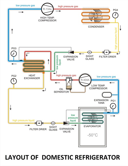
When power to the compressor is switched on, a humming sound is heard and the refrigerator is functional. The refrigerant flows through its circuit and ice is produced in the freezer. Frost, i.e., moisture from ambient air, gets deposited on the evaporator coil. Defrosting removes this frost. The water from defrosting is collected in a tray to be removed manually. Articles to be refrigerated are placed on shelves. Fruits and vegetables, which contain moisture, are stored at the base. The temperature here is around 8°C. Thus, there are temperature gradients in the refrigerator, negative temperature in the freezer and positive temperature at the base.
Applications of Refrigerator
As we studied in above article a refrigerator is a device used to maintain the lower temperature than that of its surroundings by absorbing heat from the refrigerated space and reject it into the surrounding. In past time the main use of refrigerator was only produce ice which is used for many purposes but now days the application of the refrigerator increases day by day as the new technology develops.
Some major application of the refrigerator are given as follow
- Refrigerator is used in the processing and preservation of food items.
- Refrigerator is used in industrial applications like in chemical and petroleum industry.
- Some special kind of applications.
- In food processing and preservation
An air conditioner (AC) in a room or a car works by collecting hot air from a given space, processing it within itself with the help of a refrigerant and a bunch of coils and then releasing cool air into the same space where the hot air had originally been collected. This is essentially how air conditioners work.
Window air conditioner:
Window air conditioner is sometimes referred to as room air conditioner as well. It is the simplest form of an air conditioning system and is mounted on windows or walls. It is a single unit that is assembled in a casing where all the components are located.
This refrigeration unit has a double shaft fan motor with fans mounted on both sides of the motor. One at the evaporator side and the other at the condenser side. The evaporator side is located facing the room for cooling of the space and the condenser side outdoor for heat rejection. There is an insulated partition separating these two sides within the same casing.
Front Panel The front panel is the one that is seen by the user from inside the room where it is installed and has a user interfaced control be it electronically or mechanically. Older unit usually are of mechanical control type with rotary knobs to control the temperature and fan speed of the air conditioner.
The newer units come with electronic control system where the functions are controlled using remote control and touch panel with digital display.
The front panel has adjustable horizontal and vertical (some models) louvers where the direction of air flow are adjustable to suit the comfort of the users. The fresh intake of air called VENT (ventilation) is provided at the panel in the event that user would like to have a certain amount of fresh air from the outside.
The mechanical type is usually lower in price compared to the electronic type. If you just want to cool the room and are not too particular about aesthetic or additional functions, the mechanical type will do the work.
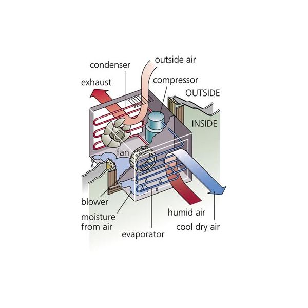
Indoor Side Components
The indoor parts of a window air conditioner include:
- Cooling Coil with an air filter mounted on it. The cooling coil is where the heat exchange happens between the refrigerant in the system and the air in the room.
- Fan Blower is a centrifugal evaporator blower to discharge the cool air to the room.
- Capillary Tube is used as an expansion device. It can be noisy during operation if installed too near the evaporator.
- Operation Panel is used to control the temperature and speed of the blower fan. A thermostat is used to sense the return air temperature and another one to monitor the temperature of the coil. Type of control can be mechanical or electronic type.
- Filter Drier is used to remove the moisture from the refrigerant.
- Drain Pan is used to contain the water that condensate from the cooling coil and is discharged out to the outdoor by gravity.
The outdoor side parts include:
- Compressor is used to compress the refrigerant.
- Condenser Coil is used to reject heat from the refrigeration to the outside air.
- Propeller Fan is used in air-cooled condenser to help move the air molecules over the surface of the condensing coil.
- Fan Motor is located here. It has a double shaft where the indoor blower and outdoor propeller fan are connected together.
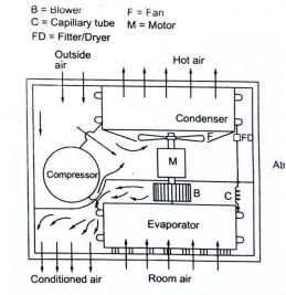
The low pressure and low temperature refrigerant vapour from evaporator is sucked by compressor. The compressor compresses the vapour to high pressure and high temperature and discharges to the condenser. On the condenser the refrigerant vapour condenses by dissipating heat to the cooling medium (air) the liquid refrigerant coming out of condenser passes through filter, dryer into capillary tube where it is again throated back to the evaporated pressure. The low pressure low temp liquid refrigerant then flows to evaporator which it boil off by extracting heat from air to be circuited to the conditioned space.
Split air conditioner
We know that the air conditioner mainly is of two type windows and split. The split name given to split system air conditioners for the very simple reason that they have two components.
There is a cabinet made of metal placed outside while the other part known as the air handler, containing the evaporator coil, is inside. The outdoor unit contains the condenser as well as the compressor, and both these parts are connected to each other using a pipe or a duct. In case of central air conditioning, there are a number of ducts used to connect different rooms, with the bigger unit placed outdoors. Almost all the central air conditioning units are split as they are more energy-efficient.
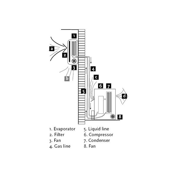
Parts of split air conditioner:
Mainly split ac divided into 2 parts indoor units and outdoor units
Wall Mounted Indoor Unit
It is the indoor unit that produces the cooling effect inside the room. The indoor unit of the split air conditioner is a box type housing in which all the important parts of the air conditioner are enclosed. The most common type of the indoor unit is the wall mounted type though other types like ceiling mounted and floor mounted are also used.
1) Evaporator Coil or the Cooling Coil:
The cooling coil is a copper coil made of number turns of the copper tubing with one or more rows depending on the capacity of the air conditioning system. The cooling coil is covered with the aluminium fins so that the maximum amount of heat can be transferred from the coil to the air inside the room.
The refrigerant from the tubing at very low temperature and very low pressure enters the cooling coil. The blower absorbs the hot room air or the atmospheric air and in doing so the air passes over the cooling coil which leads to the cooling of the air. This air is then blown to the room where the cooling effect has to be produced. The air, after producing the cooling effect is again sucked by the blower and the process of cooling the room continues.
After absorbing the heat from the room air, the temperature of the refrigerant inside the cooling coil becomes high and it flows back through the return copper tubing to the compressor inside the outdoor unit. The refrigerant tubing supplying the refrigerant from the outdoor unit to the indoor unit and that supplying the refrigerant from indoor unit to the outdoor unit are both covered with the insulation tape.
2) Air Filter:
The air filter is very important part of the indoor unit. It removes all the dirt particles from the room air and helps supplying clean air to the room. The air filter in the wall mounted type of the indoor unit is placed just before the cooling coil. When the blower sucks the hot room air, it is first passed through the air filter and then though the cooling coil. Thus, the clean air at low temperature is supplied into the room by the blower.
3) Cooling Fan or Blower:
Inside the indoor unit there is also a long blower that sucks the room air or the atmospheric air. It is an induced type of blower and while is sucks the room air it is passed over the cooling coil and the filter due to which the temperature of the air reduces and all the dirt from it is removed. The blower sucks the hot and unclean air from the room and supplies cool and clean air back. The shaft of the blower rotates inside the bushes and it is connected to a small multiple speed motor, thus the speed of the blower can be changed. When the fan speed is changed with the remote it is the speed of the blower that changes.
4) Drain Pipe:
Due to the low temperature refrigerant inside the cooling coil, its temperature is very low, usually much below the dew point temperature of the room air. When the room air is passed over the cooling due the suction force of the blower, the temperature of the air becomes very low and reaches levels below its dew point temperature. Due to this the water vapor present in the air gets condensed and dew or water drops are formed on the surface of the cooling coil. These water drops fall off the cooling coil and are collected in a small space inside the indoor unit. To remove the water from this space the drain pipe is connected from this space extending to some external place outside the room where water can be disposed of. Thus, the drain pipe helps removing dew water collected inside the indoor unit. To remove the water efficiently the indoor unit has to be a tilted by a very small angle of about 2 to 3 degrees so that the water can be collected in the space easily and drained out. If this angle is in opposite direction, all the water will get drained inside the room. Also, if the tilt angle is too high, the indoor unit will shabby inside the room.
5) Louvers or Fins:
The cool air supplied by the blower is passed into the room through louvers. The louvers help changing the angle or direction in which the air needs to be supplied into the room as per the requirements. With louvers one easily change the direction in which the maximum amount of the cooled air has to be passed.
There are two types of louvers: horizontal and vertical. The horizontal louvers are connected to a small motor and their position can set by the remote control. Once can set a fixed position for the horizontal louvers so that chilled air is passed in a particular direction only or one can keep it in rotation mode so that the fresh air is supplied throughout the room. The vertical louvers are operated manually and one can easily change their position as per the requirements. The horizontal louvers control flow of air in upper and downward directions of the room, while vertical louvers control movement of air in left and right directions.
Outdoor Unit
As mentioned previously the outdoor unit is installed outside the room to be air conditioned in the open space. In outdoor unit lots of heat is generated inside the compressor and the condenser, hence there should be sufficient flow of the air around it. The outdoor unit is usually installed at the height above the height of the indoor unit inside the room though in many cases the outdoor is also installed at level below the indoor unit.
The outdoor unit contains the important parts of the split AC like compressor, condenser, expansion valve etc. Let us see these parts in more details:
1) Compressor:
The compressor is most important part of the any air conditioner. It compresses the refrigerant and increases its pressure before sending it to the condenser. The size of the compressor varies depending on the desired air conditioning load. In most of the domestic split air conditioners hermetically sealed type of compressor is used. In such compressors the motor used for driving the shaft is located inside the sealed unit and it is not visible externally. External power has to be supplied to the compressor, which is utilized for compressing the refrigerant and during this process lots of heat is generated in the compressor, which has to be removed by some means.
2) Condenser:
The condenser used in the outdoor unit of split air conditioners is the coiled copper tubing with one or more rows depending on the size of the air conditioning unit and the compressor. Greater the tonnage of the air conditioner and the compressor more are the coil turns and rows. The high temperature and high pressure refrigerant from the compressor comes in the condenser where it has to give up the heat. The tubing is made up of copper since it rate of conduction of heat is high. The condenser is also covered with the aluminium fins so that the heat from the refrigerant can be removed at faster rate.
3) Condenser Coil
Condenser Cooling Fan:
The heat generated within the compressor has to be thrown out else the compressor will get too hot in the long run and its motor coils will burn leading to complete breakdown of the compressor and the whole air conditioner. Further, the refrigerant within the condenser coil has to be cooled so that after expansion its temperature becomes low enough to produce the cooling effect. The condenser cooling fan is an ordinary fan with three or four blades and is driven by a motor. The cooling fan is located in front of the compressor and the condenser coil. As the blades of the fan rotate it absorbs the surrounding air from the open space and blows it over the compressor and the condenser with the aluminium fins thus cooling them. The hot air is thrown back to the open space and the circulation of air continues unhindered.
4) Expansion Valve:
The expansion valve is usually copper capillary tubing with several rounds of coils. In the split air conditioners of bigger capacities thermostatic expansion valve is used which is operated electronically automatically. The high pressure and medium temperature refrigerant leaves the condenser and enters the expansion valve, where its temperature and pressure drops suddenly.
Working of split AC:
The outdoor unit of a split system air conditioner contains the refrigerant. The refrigerant is a gas pressurised into the compressor. There are many ducts or tubes in a ducted air conditioning unit through which the gas passes. This later condenses into liquid form.
This liquid then passes through the expansion joint and gets converted into a gaseous state. This releases a large amount of heat in the process.
The resultant gas is used for cooling the air at a very low temperature and hence called the refrigerant. This is a cyclic process which continues as the gas flows back into the compressor. The air of your room passes through the cavity containing evaporator coils. These coils contain gas at extremely low temperatures, thus cooling the air.
The thermostat present inside air conditioning units controls the temperature and the air continues to stay in the evaporator area till the desired temperature is obtained. It is then blown into the room.
Thus, your split system air conditioner sucks in the warm air and lowers its temperature before blowing it back into the room. The moisture inside the room condenses in the process, which is then removed through a drain pipe present in the outdoor unit.