Unit 11
Couplings, Clutches and Brakes
Content:
A coupling is a mechanical device which is used to hold two rotating shafts together. It is a permanent joint, unlike clutch which can be disengaged on the will of operator. With the help of couplings, we can join two shafts which are intersecting, collinear or parallel (with a small distance).

Rotating coupling
Oldham coupling is used to connect two parallel shafts which are a small distance apart.

Oldham coupler
Difference between clutch and coupling:
We all know that a clutch (which is generally used in automobiles) is also used for connecting two rotating shafts but there is a basic difference between a clutch and coupling. In clutch we can disengage the rotating shaft at our will whenever we want but in coupling it is not possible.
Practical example of coupling:
In our domestic electricity generator, we see that a shaft is rotated by an engine by converting chemical energy of fuel into mechanical energy. This rotating shaft of engine is then connected with the shaft of an electric alternator with the help of a coupling. And finally, the electric alternator converts mechanical energy of shaft into electric energy. Here coupling is an important part which transmits rotating motion of engine shaft to electric alternator shaft.
Requirements of a good coupling
It should be capable of transmitting torque from driving shaft to driven shaft
It should align the shafts properly
It should be able to dismantle for the purpose of maintenance
It should provide safety to man and machine in case of coupling failure
Types of couplings
There are two types of couplings
1. Rigid coupling
2. Flexible coupling
A flexible coupling can accommodate a slight misalignment between shafts (up to 0.5-degree angular misalignment and 5 mm axial misalignment) but a rigid coupling cannot tolerate any such misalignment.
Examples of rigid coupling muff coupling, clamp coupling, rigid flange coupling etc.
Example of flexible coupling is Bushed pin flexible coupling.
Difference between rigid and flexible couplings
Flexible coupling can accommodate a slight misalignment between shafts but a rigid coupling cannot accommodate any misalignment
Flexible coupling can absorb shocks and vibrations but a rigid coupling cannot absorb shocks and vibrations
Rigid coupling is simple and inexpensive but flexible couplings are expensive
Some common types of couplings are discussed below.
Muff coupling
A muff coupling is also known as a sleeve or box coupling. It is a type of rigid coupling. It consists a sleeve and a key which is used to join input and output shafts.
Advantages of muff coupling
It is simple, it has only two parts a sleeve and a key
Since it has no projecting parts hence it is safe to use
It has compact construction
It is cheaper compared to other types of couplings
Disadvantages of muff coupling
It is difficult to assemble or dismantle
Since it is a rigid coupling so it cannot accommodate any misalignment
Due to absence of flexible elements it cannot absorbs shocks and vibrations
It requires more axial space compared with other types of couplings
Clamp coupling
It is also known as compression or split muff coupling. It is a type of rigid coupling. It is same as muff coupling the only difference is in clamp coupling sleeve is divided into two axially symmetric parts. Which are assembled together to form a coupling.
Advantages of clamp coupling
It is Easy to assemble and dismantle
It is easy to remove without axial displacement of any shaft
Its diametrical dimensions are small compared to muff coupling
Disadvantages of clamp coupling
Dynamic balancing is difficult hence it is not suitable for high speed applications
It is not suitable for shock loads
Necessary to provide a guard for safety
Rigid flange coupling
As the name suggests it is a rigid coupling. It has two flanges one on driving shaft and one on driven shaft. These two flanges are joined together with the help of nut and bolt.
Advantages of rigid flange coupling
It has High torque transmitting capacity
It is easy to assemble and dismantle
It has simple construction and it is easy to design and manufacture
Disadvantages of rigid flange coupling
It cannot tolerate misalignment between shafts
It cannot used where shocks and vibrations are present
It requires some radial space
Bushed pin flexible coupling
As the name suggests it is a type of flexible coupling. It consists two flanges mounted each on input and output shaft. Both the flanges are connected with rubber bush in between, which provides resistance to shocks and slight misalignment.
Advantages of Bushed pin flexible coupling
It can tolerate slight misalignment
It can work with shocks and vibrations
It can be used for transmitting high torques
It is simple in construction
It can easily be assembled or dismantled
Disadvantages of Bushed pin flexible coupling
It has high cost due to additional parts
It requires more radial space compared with other types of couplings
- A joint or coupling that allows parts of a machine not in line with each other limited freedom of movement in any direction while transmitting rotary motion.
Universal Joint
A universal joint in its simplest form consists of two shaft yokes at right angles to each other and a four point cross which connects the yokes. The cross rides inside the bearing cap assemblies, which are pressed into the yoke eyes.
TYPES
Hooke
The Hooke style universal joint is perhaps the most widely known joint in the United States. The joint consists of two rods that are connected at the centre by a four-pin attachment. The two rods are slender on the outer half and thicker on the inner half. The Hooke u-joint was designed by Robert Hooke, curator of experiments at the Royal Society in 1662. Hooke's work was primarily focused on the mechanics of clocks and other astronomical measuring tools.
Ring and Trunnion
The ring and trunnion universal joint is designed with a female and a male rod at either end of the centre cross point. The centre cross is an open circle with four protruding points that poke through the holes on the male and female rods. Within the centre of the ring and trunnion u-joint is a bushing and a lock ring that help maintain the centre cross between the rods. The ring and trunnion is often seen inside the drive shaft of a vehicle.
Bendix-Weiss
Bendix-Weiss is a universal ball joint that has a hollow centre containing four small metal balls. The two rods are formed to hook together at a cross section and the metal balls sit in each corner socket. A fifth, smaller ball is situated in the very centre of the cross point to help stabilize the entire device during rotations. The Bendix-Weiss joint is designed to carry the exact amount of torque on one arm of the joint as on each of the other arms. This equal balance is valuable to applications involving heavy and complex vehicles in the military, for example.
The Clutch is the most important part of the engine in an automobile. A clutch uses to transfer rotating motion or torque from one shaft to another shaft when requires. The torque developed by the engine at the initial speed is very low. Therefore, it is impossible to start the engine under load.
It requires that the transmission system should provide a means of connecting and disconnecting the engine from the rest of the transmission system. Such an operation must be smooth and without shock to the passengers of the vehicle. Hence a device that uses to engage and disengage the engine from the transmission system is called a clutch.
The clutch permits the gradual taking of load when adequately operated, thereby it prevents jerky motion of the vehicle, and this avoids undue strain on the parts of the vehicle as well as passengers. In the transmission system, the system by which power developed by the engine is transmitted to road wheels to propel the vehicle.
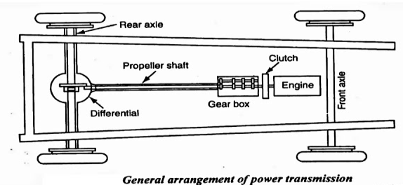
In automobiles, the power is developed by the engine which is used to turn wheels. Therefore, the engine is to be connected to the transmission systems for transferring power to wheels.
Also, there should be a system using which the engine could be engaged and disengaged with the transmission system smoothly and without shock so that the vehicle mechanism is not damaged and passengers do not feel inconvenience. A clutch is employed in automobiles for this purpose.
PARTS OF CLUTCH
The clutch consists of the following parts. We will discuss it in detail.
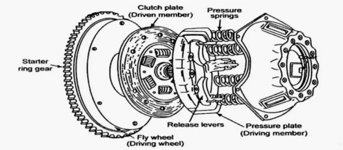
1. Flywheel
The flywheel is an integral part of the engine, which also use as a part of the clutch. It is a driving member and connects to the pressure plate of the clutch shaft is houses with bearings in a flywheel. The flywheel rotates as the engine crankshaft rotates.
2. Pilot Bearing
The pilot bearing or bushing press into the end of the crankshaft to support the end of the transmission input shaft.
The pilot bearing prevents the transmission shaft and clutch disc from wobbling up and down when the clutch releases. It also assists the input shaft centre of the disc on the flywheel.
3. Clutch plate or Disc plate
It is the driven member of the single-plate clutch and line with friction material on both surfaces. It has a central hub with internal splines to limit the axial travel along the splined gearbox driving shaft.
This helps to provide damping actions against torsional vibrations or variations of the driving torque between engine and transmission. A clutch disc is a plate between flywheel and friction or pressure plate. It has a series of facings inverters on each side to enlarge the friction. These clutch facings are made of asbestos material. They are highly worn and heat resistant.
4. Pressure plate
The pressure plate is made of special cast iron. It is the heaviest part of the clutch assembly. The main function of the pressure plate is to establish even contact with the driven plate facing through which the pressure springs can exert a sufficient force to transmit the full torque of the engine.
The pressure plate presses the clutch plate on to the flywheel from its machined surface. Between the pressure plate and clutch cover assembly, pressure springs are fits. The pressure will be withdrawn from the flywheel whenever release levers depress by the toggle or release levers pivots accordingly.
5. Clutch cover
The clutch cover assembly bolts to the flywheel. It consists of a pressure plate, release lever mechanism, clutch cover, and pressure springs. Generally, the clutch plate revolves with the flywheel.
However, when the clutch has disengaged, the flywheel, as well as the pressure plates are free to rotate independently from the driven plate and driving shaft.
6. Release levers
These pivots on pins to the clutch cover, their outer ends locate and positions on pressure plate legs and the inner ends are projecting towards the clutch shaft. A careful and accurate adjustment of the release mechanism is one of the most important factors governing the performance of a clutch assembly.
7. Clutch shaft
It is a component of the gearbox. Since it is a splined shaft to the hub of the clutch plate, which is sliding on it. One end of the clutch shaft attaches to the crankshaft or flywheel and the other end connects to the gearbox or forms a part of the gearbox.
WORKING OF CLUTCH
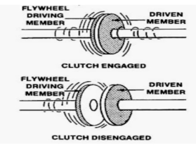
A Clutch is defined as a system that is used to connect or disconnect the engine from the rest of the transmission elements.
It is located between the engine and gearbox. During normal running and stationary position, it is always in the engaged condition.
The clutch disengages when the driver processes the clutch pedal. The clutch disengages for starting, changing gears, stopping, and idling.
When the clutch engages, the engine will connect to the transmission, and power flows from the engine to rear wheels through a transmission system When the clutch disengages by pressing the clutch pedal, the engine will disengage from the transmission. Thus, the power does not flow to rear wheels while the engine is still running.
NECESSITY OF CLUTCH IN AUTOMOBILE
The clutch is a device that is necessary to transmit power from the engine to the wheels of the vehicle by engaging the engine to the transmission system gradually without giving the jerks to the body of the vehicle.
PRINCIPLES OF CLUTCH

The clutch works on the principle of friction. In Figure, the driving shaft A with flange C is rotating at 'N' rpm, and shaft B with the flange D is keyed to the driven shaft which is in a stationary position when the clutch is not engaged. Now, an external force is applied to the flange D so that it comes in contact with flange C.
As soon as the contact is made, they are united due to friction between them and the flange D starts rotating with flange C.
The rotational speed of flange D depends on the friction between surfaces C and D which in turn is proportional to the external force applied.
If the force gradually increases, the speed force transmitted will also increase gradually. The torque transmitted by the friction clutch depends on the pressure applied on the flange, coefficient of friction of the surface materials, and radius of the flange. By increasing any of them, the force transmitted can increases.
FUNCTIONS OF CLUTCH
1. To allow the engagement or disengagement of gear when the vehicle is stationary and the engine is running.
2. To transmit the engine power to rear wheels smoothly without shocks to the transmission system when the vehicle is in motion.
3. To permit the engaging of the gears when the vehicle is in motion without damaging gear wheels.
READ | What Is Multi-Plate Clutch - Types, Working, Pros & Cons, and Diagram
REQUIREMENTS OF A CLUTCH
A clutch must have the following requirements.
1. The clutch should be able to engage gradually and positively without the occurrence of sudden jerks.
2. It should be capable of transmitting maximum torque to the engine.
3. The design of the clutch is such that it should ensure the dissipation of heat sufficiently which is generated during operation.
4. The clutch should dynamically balance to the vibration in the transmission system. It is a very important requirement in modern cars which operate at high speed.
5. The size of the clutch should be as small as possible so that it will occupy minimum space.
6. The suitable mechanism should incorporate within the clutch for damping of vibration and elimination of noise produces during the transmission.
7. To reduce effective clamping load on the car thrust bearing as well as wear on it, a provision should be made for clutch-free pedal play.
8. The clutch must have the non-tiresome operation of disengagement for the driver for higher power transmission.
TYPES OF CLUTCHES
The clutches used in motor vehicles are almost similar in construction and operation. There are individual differences in the details of their linkages as well as in the pressure plate assemblies.
DIFFERENT TYPES OF CLUTCHES ARE CLASSIFIED AS FOLLOWS
- Friction Clutch - Single Plate Clutch | Multi-Plate Clutch - Wet Clutch & Dry Clutch | Cone Clutch
- Centrifugal clutch
- Semi-centrifugal clutch
- Hydraulic clutch
- Conical spring clutch or Diaphragm clutch
- Positive clutch or Dog and Spline Clutch
- Vacuum clutch
- Electromagnetic clutch
APPLICATIONS OF CLUTCH
Clutches have various applications according to their types. The clutch not only uses for automobile purposes but also for industrial purposes.
Automobile Use - Heavy vehicles, four-wheelers such as cars, trucks, buses, Two-wheelers, mopeds, scooters, bikes.
Industrial Use - Metal stamping, Press working, packing machines, indexing tables, Assembling machines, Printing machines, Conveyor belts, Pumps, Gear drives.
Disc clutch
A clutch disc is a part of a manual transmission, also known as the friction lining. It is in between the pressure plate and the flywheel, mainly composed of two things the splined hub and a metal plate where you can find friction linings. The main purpose of it is to help the splines from the centre to work or get engaged with the splines on the input shaft. Because of that, the input shaft and disc will turn together, while the disc can still slide back and forth on the shaft.
If you will look closely, you will find small coil springs right between the friction disc and the clutch disc splined hub. These are called the torsion spring or damping spring. When a clutch engagement happens, these torsion springs will absorb the vibrations or the shocks that may possibly be produced. On the other hand, those flat coil springs under the friction lining are called the facing spring or cushioning springs. These are responsible for smooth engagements and to help the lining flex slightly during the initial engagement.
The clutch disc has several protections to ensure that it won’t be damaged under stressful circumstances. The disc lining is made of cotton fibres, copper wires and heat-resistant asbestos.
Centrifugal clutch
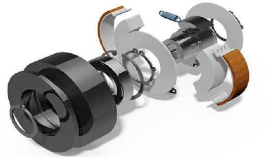
A centrifugal clutch is a mechanical device which is used on driven rotary equipment. Most commonly used with a combustion engine, the clutch can be used to automatically transmit the torque from the drive to the driven equipment giving a “soft start” with no load engagement. By using this type of clutch between the drive and the driven equipment the speed at which the mechanical driven shaft engages can be controlled. As the engine speed is increased to or above the set engagement speed of the centrifugal clutch the mechanical drive will become engaged. This enables the operator to run the engine at a designated idling speed without driving the equipment, thus allowing the engine to reach its optimal torque before experiencing load.

Advantages and Disadvantages of Using A Centrifugal Clutch
Using a centrifugal clutch on engine driven equipment enables the engine to be started under a no-load situation. When the engine is idling the drive remains disengaged. Only when the rpm of the engine is increased to the set engagement speed of the clutch or above will the drive be fully connected. This results in a smooth engagement and prevents the engine from stalling. It also helps protect the engine by ensuring high levels of torque are not transmitted back through the flywheel of the engine. In circumstances such as this, for example when the rotating equipment is for some reason jammed, the extreme levels of torque transmitted back through the engine can cause significant and in some cases irreparable damage to the engine. This can be a very costly and sometimes economically unfeasible to repair the equipment. By using a centrifugal clutch, this can be avoided as the components of the clutch will take the overload. The wearing parts of a clutch are easy and cost effective to replace. In addition to providing a no-load situation the set engagement speed of the clutch also allows the operator to control at what point the rotary equipment becomes engaged. This allows the engine of the machinery to be running but without necessarily operating.
Due to the nature of centrifugal clutch being a purely mechanical automatic engagement at a pre-determined speed, each application may require a specific configuration. Meaning this pre-set engagement speed cannot be changed without altering internal components.
How Does A Centrifugal Clutch Work?
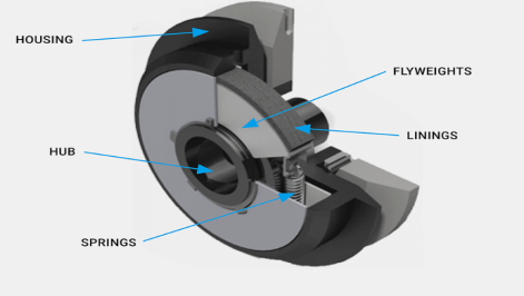
A centrifugal clutch works, as the name suggests, through centrifugal force. The key components of a centrifugal clutch are the hub, flyweights (clutch shoes), springs, linings and housing (shown in the diagram below). The centrifugal force, created by the revolutions of the engine is transmitted through two or more flyweights. The clutch can be driven by a number of ways depending upon the design of the machinery. One of the most common methods is by mounting the clutch onto the parallel or taper crank shaft of the engine. When the crank shaft rotates the shaft of the clutch rotates at the same speed as the engine. The rotation of the hub forces the shoes or flyweights outwards until they come into contact with the clutch drum, the friction material transmits the torque from the flyweights to the drum. The drive is then connected. The springs, flyweights and the friction material are responsible for determining the speed at which the clutch engages. Depending on the design of the machine the output from the clutch can be one of a variety drives, including but not limited to shaft, pulley, sprocket or flange.
Centrifugal Clutch Applications
A centrifugal clutch can be useful for a range of engine driven equipment with a high starting inertia. They are commonly found on mobile equipment with rotating parts that are driven by small diesel or petrol engines. Some of these examples include:
- Vibratory plate compactors and rollers
- Rammers
- Compressor/vacuum/fan drives
- Trowel and concrete finishers
- Compact road/street cleaners
- Transport refrigeration units
- Mobile water pumps
- Ground care equipment – rotary and flail mowers, turf cutters and scarifies
- Go-karts
- Woodchoppers/stump grinders/milling cutters
Brake
Brake is a device used for device for slowing or to control its speed to a certain value under varying conditions or stopping a vehicle or other moving mechanism by the absorption or transfer of the energy of momentum, usually by means of friction.
Where brakes are used?
The usual answer is in a car or a vehicle where safe, fast and smooth stopping when required or simply when there is a need to stop at a stop sign or in a driveway. And not always brakes are used to bring the vehicle to a full stop. For slowing down in traffic or to turn round a curve requires braking to decrease the speed from a higher to a lower speed.
Brake is also used in elevators, escalators, hoists, and winches, which must stop and hold a load after lifting it. Also, in machine tools, conveyors, and other manufacturing equipment must often be brought to a safe, quick stop employs brakes.
Classification of Brakes
- Drum brakes
- Band brake
- Cone brake
- Disk or axial brake
Drum Brakes
Drum brakes apply friction to the external or internal circumference of a cylinder. A drum brake consists of the brake shoe, which has the friction material bonded to it, and the brake drum. For braking, the shoe is forced against the drum developing the friction torque. Drum brakes can be divided into two groups depending on whether the brake shoe is external or internal to the drum.
1. Internally expanding shoes
2. Externally contracting shoes
Internal expanding shoe brake
Most drum brakes use internal shoes that expand against the inner radius of the drum with brake lining. Internal drum brakes are used in automotive applications. A drum brake consists of two brake shoes and linings supported on a back plate bolted to the axle casing of drum. The shoes are pivoted at one end on anchor pins fixed on to the back plate. The brake can be actuated by a double hydraulic piston expander or cams, which forces the free ends of the brake so that the shoes come into frictional contact with the rotating brake drum. The leading shoe is identified as the shoe whose expander piston moves in the direction of rotation of the drum. The trailing shoe is the one whose expander piston moves in the direction opposite to the rotation of the drum.
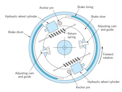
Internal Expanding shoe brake
Band Brake
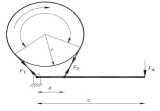
One of the simplest types of braking device is the band brake. This consists of a flexible metal band lined with a frictional material wrapped partly around a drum. The brake is actuated by pulling the band against the drum as illustrated in figure.
Disk Brakes
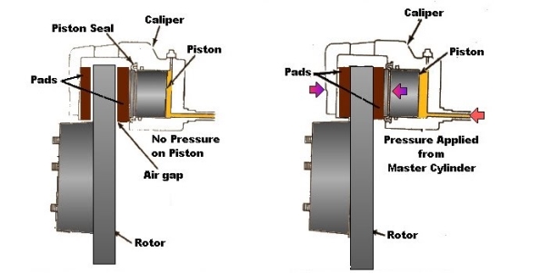
Disc brakes are familiar and common from in automotive applications. They are used extensively in cars and bikes. Disk Brakes consist of a cast iron disc, bolted to the wheel hub. This is sandwiched between two pads actuated by pistons supported in a calliper mounted on the stub shaft . When the brake pedal is pressed, hydraulically pressurized fluid is forced into the cylinders pushing the opposing pistons and brake pads into frictional contact with the disc. The advantages of this form of braking are steady braking, easy ventilation, balancing thrust loads and design simplicity. The use of a discrete pad allows the disc to cool as it rotates, enabling heat transfer between the cooler disc and the hot brake pad.
