Unit 12
Transmission of Motion and Power
Content:
Axles are rotating or non-rotating members which are subjected to only bending moments due to members supported by it. It does not transmit torque. In other words, an axle is not twisted it only bends.
Shafts are rotating members which are subjected to bending moments and twisting moments and sometimes to axial loads.
It twists and transmits power.
BELT DRIVES:
The belt drive is used to transmit power from one shaft to another by means of pulleys which rotate at the same speed or at different speed.
Open and cross belt drive
- Open Belt Drive:
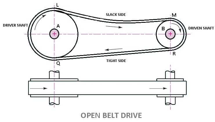
- In these types of belt drive, the belt is employing when the two parallel shafts have to rotate in the same direction.
- When the shafts are far apart, the lower side of the belt should be the tight side and the upper side must be the slack side.
- This is because, when the upper side becomes the slack side, it will sag due to its own weight and thus increase the arc of contact.
- In open belt drive, belt proceeds from top of one pulley to the top of other pulley without crossing.
- Contact angle (or wrap angle) between the belt and pulley is comparatively small (always below 180º in smaller pulley).
LENGTH OF OPEN BELT DRIVE FORMULA:
= π (r1 + r2) + 2x + (r1 – r2)2 /x ……………. (In terms of pulley radii)
= π/2 (d1 + d2) + 2x + (d1 – d2)2/ 4x ……….… (In terms of pulley diameters)
2. Cross Belt Drive
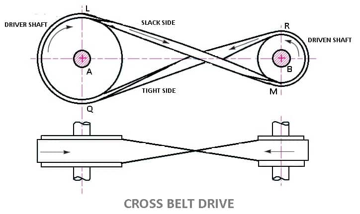
- In this types of belt drives, the belt is employing when two parallel shafts have to rotate in the opposite direction. At the junction where the belts cross, it rubs against itself and wears off.
- To avoid excessive wear, the shafts must be placed at a maximum distance from each other and operated at very low speeds.
- Contact angle between the belt and pulley is comparatively large (always above 180º in smaller pulley).
- In crossed belt drive, belt proceeds from top of one pulley to the bottom of another pulley and thus crosses itself.
- Here belt bends in two different planes in every rotation during its operation
- Cross belt drive can be advantageously applied for horizontal, inclined and vertical positions of driving and driven shafts.
- It can transmit more power as wrap angle is more.
LENGTH OF CROSS BELT DRIVE
= π (r1+r2) + 2x + (r1+r2)2 /x …………… (In terms of pulley radii)
= π/2(d1+d2) +2x + (d1 + d2)2/ 4x …………(in terms of pulley diameters)
Material of belts:
The Materials used for belts and ropes must be strong, flexible, and durable. It must have high coefficient of friction: like
1- Leather belts
2- Cotton belts
3- Rubber belts
4- Balata belts
1. Leather belts :
The leather may be oak tanned or mineral salt tanned. Example chrome tanned. When the thickness of the belt required is more then, two or more strips are cemented together. Leather belts require periodic cleaning.
2. Cotton belts or Fabric belts :
Fabric belts are made by folding canvas or cotton ducks in layers and stitching together. The fabric belts are cheaper and best suited in warm climates, damp atmospheres. These are mostly used in Farm machinery, belt conveyor etc.
3. Rubber belts :
Rubber belts are made of Fabric with rubber layer. Rubber belts are used in sawmills, paper mills, etc.
4. Balata Belts:
Balata belts are similar to rubber belts except that balata gum is used in place of rubber. Balata belts are acid proof and water proof and it is not affected by animal oils or alkalis. The balata belts should not be at temperatures above 40° C because at this temperature the balata begins to soften and becomes sticky. The strength of balata belts is 25 percent higher than rubber belts.
Type of belts:
Different types of belt are as follows
- Flat Belt
- V – Belt
- Circular Belt

1. Flat Belt :
Flat belt has a rectangular cross section. Flat belts are capable of transmitting power over long distance between pulley centres. The efficiency of this drive is around 98 % and produces less noise.
This belt is mostly used in factories and workshops, where a moderate amount of power is to be transmitted, from one pulley to another when two pulleys are not more than 8 metres apart.
Flat belts drives are of following types:
- Open belt drive.
- Cross belt drive.
- Stepped or cone pulley or speed cone drive.
- Fast and loose pulleys.
- Jockey pulley drive or belt drive with idler pulley
- Compound Belt Drive System
2. V – Belt:
V-Belts also used with grooved pulleys; V-belts are trapezoidal in cross section. V-belts permit large speed ratios and can transmit higher power. Multiple drives are possible.
This belt is mostly used in factories and workshops, where a moderate amount of power is to be transmitted, from one pulley to another when two pulleys are very near to each other.
3. Circular Belt or Round Belt :
Circular Belt or Round belt has a circular cross section and is used with grooved pulleys, this belt is mostly used in factories and workshops, where a great amount of power is to be transmitted, from one pulley to another when two pulleys are more than 8 metres apart.
Length of belt of open and cross drive:
Length of Open belts drive:
We have discussed that in an open belt drive, both the pulleys rotate in the same direction as shown in Fig. 1.
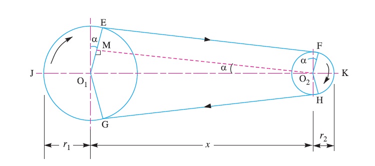
Let r1 and r2 = Radii of the larger and smaller pulleys,
x = Distance between the centres of two pulleys (i.e. O1O2), and
L = Total length of the belt.
Let the belt leaves the larger pulley at E and G and the smaller pulley at F and H as shown in Figure. Through O2 draw O2M parallel to FE.
From the geometry of the figure, we find that O2M will be perpendicular to O1E.
Let the angle MO2O1 = α radians.
We know that the length of the belt,
L = Arc GJE + EF + Arc FKH + HG
= 2 (Arc JE + EF + Arc FK) ……………………..(i)
From the geometry of the figure, we also find that
Sin α = O1M/O1O2 = O1E – EM / O1O2 = r1 – r2 / x
Since the angle α is very small, therefore putting
sin α = α (in radians) = r1 – r2 / x …………………….(ii)
∴ Arc JE = r1 (π/2 + α) ………………………….(iii)
Similarly, arc FK = r2 (π/2 – α) ……………………..(iv)
And EF = MO2 = [(O1O2)2 – (O1M)2]0.5
= [x2 – (r1 – r2)2]0.5
= x [1 – {(r1-r2) /x }2 ]0.5
Expanding this equation by binomial theorem, we have
EF = x [1 – {0.5 {(r1 – r2)/x} + …] = x – (r1 – r2)2 /2x …………………..(v)
Substituting the values of arc JE from equation (iii), arc FK from equation (iv) and EF from equation (v) in equation (i), we get
L = 2 [r1(π/2 +α) + x – {(r1-r2)2/2x} + r2(π/2 -α)]
= 2 [{r1 × π/2} + {r1×α} + x – {(r1- r2)2/2x} + {r2 × π/2} - {r2×α}]
= 2 [π/2(r1+r2) + α(r1-r2) +x – {(r1-r2)2/2x}]
= π(r1+r2) + 2α(r1-r2) +2x – {(r1-r2)2/x}
Substituting the value of α = (r1-r2)/x from equation (ii), we get
L = π(r1+r2) + 2{(r1-r2)/x}{(r1-r2)} +2x – {(r1-r2)2/x}
= π(r1+r2) + 2{(r1-r2)2/x} + 2x – {(r1-r2)2/x}
= π (r1 + r2) + 2x + (r1 – r2 )2 /x ……………. (in terms of pulley radii)
= π/2 (d1 + d2) + 2x + (d1 – d2)2 /4x …… (in terms of pulley diameters)
Length of cross belt drive:
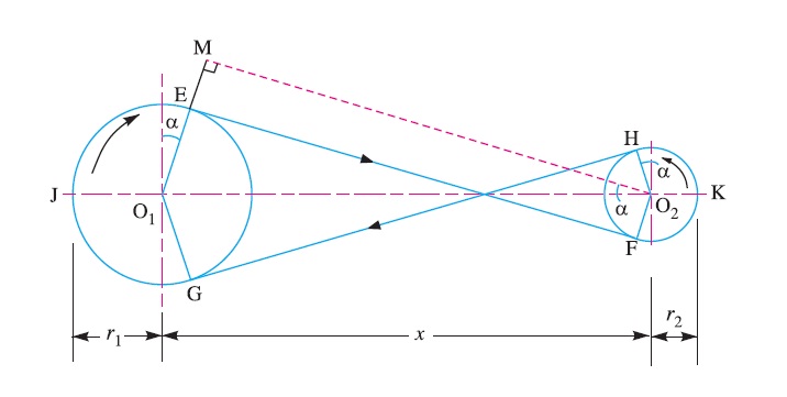
We have discussed that in a cross belt drive, both the pulleys rotate in the opposite directions as shown in Fig
Let r1 and r2 = Radii of the larger and smaller pulleys,
x = Distance between the centres of two pulleys (i.e. O1O2 ), and
L = Total length of the belt.
Let the belt leaves the larger pulley at E and G and the smaller pulley at F and H as shown in Figure.
Through O2 draw O2M parallel to FE.
From the geometry of the figure, we find that O2M will be perpendicular to O1E.
Let the angle MO2O1 = α radians.
We know that the length of the belt,
L = Arc GJE + EF + Arc FKH + HG
= 2 (Arc JE + FE + Arc FK) …………………(i)
From the geometry of the figure, we find that
Sin α = O1M/O1O2 = (O1E + EM)/O1O2 = r1+r2 / x
Since the angle α is very small, therefore putting sin α = α (in radians = r1+r2 / x ………………………….…(ii)
Arc JE = r1 (π/2 + α) ……………. ……(iii)
Similarly, arc FK = r2 (π/2 + α) ………………(iv)
EF = MO2 = [(O1O2 )2 – (O1M)2]0.5
= [x2 – (r1 + r2 )2]o.5
= x [1- (r1+r2 /x )2 ]0.5
Expanding this equation by binomial theorem, we have
EF = x [1- 1/2(r1+r2 /x)2 + …] = x – [(r1+r2)2/2x] ……………………(v)
Substituting the values of arc JE from equation (iii), arc FK from equation (iv) and EF from equation (v) in equation (i), we get,
L = 2 [r1(π/2 +α) + x – {(r1+r2)2/2x} + r2(π/2 +α)]
= 2 [{r1 × π/2} + {r1×α} + x – {(r1+r2)2/2x} + {r2 × π/2} + {r1×α}]
= 2 [π/2(r1+r2) + α(r1+r2) +x – {(r1+r2)2/2x}]
= π(r1+r2) + 2α(r1+r2) +2x – {(r1+r2)2/x}
Substituting the value of α = (r1+r2)/x from equation (ii), we get
L = π(r1+r2) + 2{(r1+r2)/x}{(r1+r2)} +2x – {(r1+r2)2/x}
= π(r1+r2) + 2{(r1+r2)2/x} + 2x – {(r1+r2)2/x}
= π (r1+r2) + 2x + (r1+r2)2 /x …………… (In terms of pulley radii)
= π/2(d1+d2) +2x + (d1 + d2)2/ 4x …………(in terms of pulley diameters)
Velocity ration for simple and compound belt drive:
It is the ratio between the velocities of the driver and the follower or driven. It may be expressed, mathematically, as discussed below:
Let d1 = Diameter of the driver,
d2 = Diameter of the follower,
N1 = Speed of the driver in r.p.m.,
N2 = Speed of the follower in r.p.m.,
∴ Length of the belt that passes over the driver, in one minute
= π d1 N1
Similarly, length of the belt that passes over the follower, in one minute
= π d2 N2
Since, the length of belt that passes over the driver in one minute is equal to the length of belt that passes over the follower in one minute, therefore
= π d1 N1 = π d2 N2
And velocity ratio,
= N2/N1 = d1/d2
When thickness of the belt (t) is considered, then velocity ratio,
= N2/N1 = (d1 + t)/ (d2 + t)
The velocity ratio of a belt drive may also be obtained as discussed below:
We know that the peripheral velocity of the belt on the driving pulley,
ν1 = (π d1 N1)/60, m/s
And peripheral velocity of the belt on the driven pulley,
ν2 = (π d2 N2)/60, m/s
When there is no slip, then ν1 = ν2.
(π d1 N1)/60 = (π d2 N2)/60
N2/N1 = d1/d2
In case of a compound belt drive, the velocity ratio is given by
= N4/N1 = (d1 × d3)/(d2 × d4)
= Speed of last driven / Speed of first driver = Product of diameters of drivers / Product of diameters of drives
We have seen in belts that slipping is occurs. In order to avoid slipping steel chains are used. The chain are made up of rigid links which are hinged together in order to provide the necessary flexibility for wrapping around the driving and driven wheel. The tooth wheels are known as sprocket wheels or simple sprockets.
A chain drive is a mechanically operating system where we used different types of chains to transmit the power or for movement of something.
Generally, a chain drive is used where the distance between the power produced and where it to be transferred is less, however, this is not applicable for all. In some cases, we can use a chain drive for longer distances power transfer. In belt or rope drive we see there is some percent of slip occurs, but in the chain, there will be no slip. But this does not mean that 100% power is transmitted from one to another device due to friction loss some amount of power loss we can generally see.
![Chain Drives: 5 Types of Chains [Advantages/Disadvantages]](https://glossaread-contain.s3.ap-south-1.amazonaws.com/epub/1643036240_2298086.jpeg)
In chain drive, the speed ratio remains constant which is a major advantage of chain drive and here there is no slippage and in case of belt drive, there is slippage so speed ratio changes as per slippage. A chain is made by a number of links and those are connected by the help of a pin.
Chains are run over a wheel named sprocket which has several amounts of teeth around the circumference of that to grip the chain, however, not all the chains need that sprocket to run over
Types of Chains:
In the field of Mechanical Engineering chains drive can be classified into three broad categories and those are:
- Hoisting Chains
- Conveyor Chains
- Power transmission Chains.
1) HOISTING CHAINS:
A hoist is a mechanical device which is used to lift a load or lowering a load, it can be used for shifting of some heavy product from one place to another place in a workstation. The chains used in this type of devices is named hoist chain, these chains are quite strong to handle heavyweight.
Hoist chains can be classified into two categories:
- Oval-Link Chains.
- Stud-Link Chains.
i) Oval-Link Chains:
It is one of the common types of chain used in hoist; it consists of many oval links attached to each other. These types of chains are also called Coil Chains. Links of this type of chain is oval. However, there are square link types of chains that are also available, but the kinking is occurred easily due to high loading.
Ii) Stud-Link Chains:
The stud-link chains used to minimize the deformation and link or tangle easily. In this type of chain, a round bar or stud is used to fit inside the oval-link chains to provide more strength to the chain. The stud-link chains used to minimize the deformation and link or tangle easily. In this type of chain, a round bar or stud is used to fit inside the oval-link chains to provide more strength to the chain. It is used in Ship to up and down the anchor of the ships, and some crane hoist where we need to lift a very high amount of load.
2) CONVEYOR CHAINS:
As the name suggests conveyor chains that means these types of chains are mostly used in the conveyor. The conveyor is a mechanical device system that is used to move the materials from one place to another. This type of chain is well shaped that it can easily run over the sprocket.
Generally, this type of chain is made of malleable cast iron and used in Low-Speed Machinery approx. 2 m/s.
The one major disadvantage of this type of chain is the motion of the chain is not smooth; there are chances of wear and tear out.
Conveyor Chains are categorized into following types:
- Detachable or Hook Joint types Conveyor chain.
- Closed-end pintle type conveyor chain.
- Detachable or Hook Joint types Conveyor chain: Detachable or Hook Joint types Conveyor chains are used in a conveyor where the length between power transmissions is short.
- Closed-end pintle type conveyor chain: This type of chain is consists of a barrel and link and made in a single casting, and then the chain is heat-treated to provide higher strength.
3) POWER TRANSMISSION CHAINS:
You can easily find out by name of the chain that it is used to transmit the power. This type of chain is made of steel and sometimes it heats treated to minimize wear and tear. This type of chain has greater accuracy and can easily run over the sprocket.

In the world of mechanical power transmission, gear drives have a very special and prominent place. This is the most preferred technology when you need to transmit considerable power over a short distance with a constant velocity ratio. The mechanism of gear drives is quite simple – the teeth, which are cut on the blanks of the gear wheel, mesh with each other to transmit power. To avoid slipping, the projections on one disc mesh with the recesses on other disc in gear drives.
This technology uses different types of gears for power transmission. In fact, it can transmit power not only between parallel shafts, but also between non-parallel, co-planar, and intersecting etc. shafts.
The following are the advantages of gear drives:
- They are positive and non-slip drives
- Large and constant velocity ratio of 60:1 can be obtained by using gear trains with minimum space
- Gear drives are mechanically strong, allowing scopes for lifting higher loads
- Longer service life compared to both belt and chain drives
- They can transmit large power
- Gear drives have high transmission efficiency
- They can transmit motion over small centre distance of shafts
- These drives are ideal for low, medium, high power transmission
- Gears can transmit motion even between non-parallel intersecting shafts
- These are the most compact compared to belt and chain drives
Unfortunately, gear drives too have certain disadvantages:
- Gear drives cannot be used for shafts with large centre distances
- They are not ideal for large velocities
- These drives require regular lubrication and a more complicated process of applying it
- Noise and vibrations are increased at a high speed
- They are less economical compared to belt and chain drives
- Using multiple gears increase the machine’s overall weight
- They have no flexibility
- Not suitable for transmitting motion over a large distance
- Some part of the machine can get permanently damaged because of the toothed wheel of gears. This is more common in case of excessive loading
Gear:
A gear is a kind of machine element in which teeth are cut around cylindrical or cone shaped surfaces with equal spacing. By meshing a pair of these elements, they are used to transmit rotations and forces from the driving shaft to the driven shaft. Gears can be classified by shape as involute, cyclonical and trochoidal gears. Also, they can be classified by shaft positions as parallel shaft gears, intersecting shaft gears, and non-parallel and non-intersecting shaft gears.
Type of gear:
Following are the different types of gears:
- Parallel gears
- Spur Gears
- Helical Gears
- Double Helical or Herringbone Gears.
- Intersecting gears
- Spiral gears
- Bevel Gears
- Non-intersecting and Non-Parallel gears.
- Worm Gears
- Rack and Pinion gears
1) Parallel gears - As indicated by the name, parallel configurations involve gears connected to rotating shafts on parallel axes within the same plane. The rotation of the driving shaft (and the driving gear) is in the opposite direction to that of the driven shaft (and driven gear), and the efficiency of power and motion transmission is typically high.
a) Spur gear:
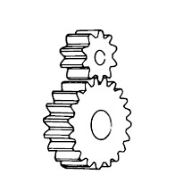
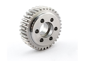
Spur gears transmit power through shafts that are parallel. The teeth of the spur gears are parallel to the shaft axis. This causes the gears to produce radial reaction loads on the shaft, but not axial loads. Spur gears tend to be noisier than helical gears because they operate with a single line of contact between teeth. While the teeth are rolling through mesh, they roll off of contact with one tooth and accelerate to contact with the next tooth. This is different than helical gears, which have more than one tooth in contact and transmit torque more smoothly.
b) Helical Gear:
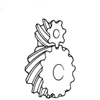
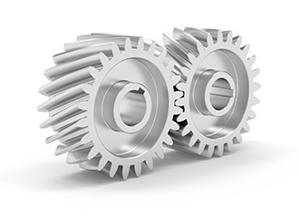
Helical gears have teeth that are oriented at an angle to the shaft, unlike spur gears which are parallel. This causes more than one tooth to be in contact during operation and helical gears are capable of carrying more load than spur gears. Due to the load sharing between teeth, this arrangement also allows helical gears to operate smoother and quieter than spur gears. Helical gears produce a thrust load during operation which needs to be considered when they are used. Most enclosed gear drives use helical gears.
c) Double Helical Gear:
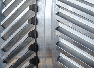
Double helical gears are a variation of helical gears in which two helical faces are placed next to each other with a gap separating them. Each face has identical, but opposite, helix angles. Employing a double helical set of gears eliminates thrust loads and offers the possibility of even greater tooth overlap and smoother operation. Like the helical gear, double helical gears are commonly used in enclosed gear drives.
d) Herringbone Gear
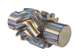
Herringbone gears are very similar to the double helical gear, but they do not have a gap separating the two helical faces. Herringbone gears are typically smaller than the comparable double helical, and are ideally suited for high shock and vibration applications. Herringbone gearing is not used very often due to their manufacturing difficulties and high cost.
2) Intersecting gears
Bevel gear: Bevel gears are most commonly used to transmit power between shafts that intersect at a 90 degree angle. They are used in applications where a right angle gear drive is required. Bevel gears are generally more costly and are not able to transmit as much torque, per size, as a parallel shaft arrangement.
Bevel gear transmits power between two intersecting shafts at any angle or non-intersecting shaft. They are classified as straight and spiral tooth bevel and hypoid gears. These are gears cut from conical blanks and connect intersecting shaft axes.
The connecting shaft is generally at 90°and sometimes one shaft drives a bevel gear which is mounted on a through the shaft resulting in two output shafts. The point of intersection of the shaft is called the apex and the teeth if the two gears converge at the apex.
There are several types of bevel gears available differentiated mainly by their tooth design. Some of the more common types of bevel gears include straight, spiral, and Zero bevel gears.
a) Straight Bevel Gears
The most commonly used of the bevel gear tooth designs due to its simplicity and, consequently, its ease of manufacturing, straight bevel teeth are designed such that when properly matched straight bevel gears come into contact with one another, their teeth engage together all at once rather than gradually. As is the issue with spur gears, the engagement of straight bevel gear teeth results in high impact, increasing the level of noise produced and amount of stress experienced by the gear teeth, as well as reducing their durability and lifespan.
b) Spiral Bevel Gears
In spiral bevel gears, the teeth are angled and curved to provide for more gradual tooth engagement and more tooth-to-tooth contact than with a straight bevel gear. This design greatly reduces the vibration and noise produced, especially at high angular velocities (>1,000 rpm). Like helical gears, spiral bevel gears are available with right-hand or left-hand angled teeth. As is also the case with helical gears, these gears are more complex and difficult to manufacture (and, consequently, more expensive), but offer greater tooth strength, smoother operation, and lower levels of noise during operation than straight bevel gears.
Additional Bevel Gear Designs
Other than the types mentioned above, there are several other designs of bevel gears available including miter, crown, and hypoid gears.
c) Miter: Miter gears are bevel gears which, when paired, have a gear ratio of 1:1. This gear ratio is a result of pairing two miter gears with the same number of teeth. This type of bevel gear is used in applications which require a change only to the axis of rotation with speed remaining constant. When two bevel gear has their axes at right angles and is equal sizes, they are called mitre gears.
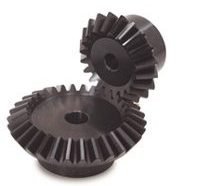
d) Crown: Crown gears, also referred to as face gears, are cylindrical (rather than conical) bevel gears with teeth cut or inserted perpendicular to the gear face. Crown gears can be paired either with other bevel gears or, depending on the tooth design, spur gears.
e) Hypoid: Originally developed for the automobile industry, hypoid gears, unlike the previously mentioned types, are a type of spiral bevel gear used for non-parallel, non-intersecting configurations. This design allows for components to be placed lower, allowing for more space in the sections above. Employing curved and angled teeth similar to those used in spiral bevel gears, hypoid gears are even more complex and, consequently, more difficult (and costly) to manufacture.
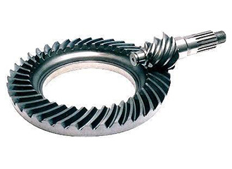
Hypoid gears look very much like a spiral bevel gear but they operate on shafts which do not intersect, which is the case with a spiral bevel gear. In the hypoid arrangement because the pinion is set on a different plane than the gear, the shafts are supported by the bearings on either end of the shaft.
3) Non-intersecting and Non-Parallel gears.
a) Worm Gears: worm gear pairs are comprised of a worm wheel typically a cylindrical gear paired with a worm i.e., a screw-shaped gear. These gears are used to transmit motion and power between non-parallel, non-intersecting shafts. They offer large gear ratios and capabilities for substantial speed reduction while maintaining quiet and smooth operation.
Worm gears transmit power through right angles on non-intersecting shafts. Worm gears produce thrust load and are good for high shock load applications but offer very low efficiency in comparison to the other gears. Due to this low efficiency, they are often used in lower horsepower applications.
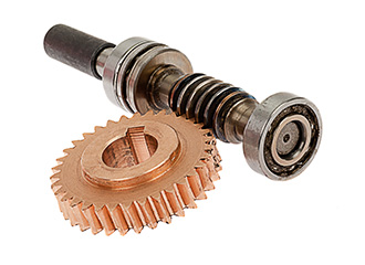
One distinction of worm gear pairs is that the worm can turn the worm wheel, but, depending on the angle of the worm, the worm wheel may not be able to turn the worm. This characteristic is employed in equipment requiring self-locking mechanisms. Some of the disadvantages of worm gears are the low transmission efficiency and the amount of friction generated between the worm wheel and worm gear which necessitates continuous lubrication.
4) Rack and Pinion Gears
A rack and pinion is a pair of gears which convert rotational motion into linear motion and vice versa. A circular gear called “the pinion” engages teeth on a linear “gear” bar called “the rack”.
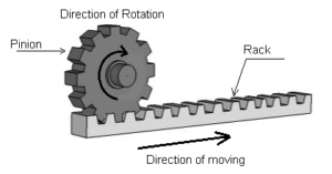
Rotational motion applied to the pinion will cause the rack to move to the side, up to the limit of its travel. The diameter of the gear determines the speed that the rack moves as the pinion turns.
A rack and pinion is commonly found in the steering mechanism of cars or other wheeled, steered vehicles. In a rack railway, the rotation of a pinion mounted on a locomotive or a railcar engages a rack between the rails and pulls a train along a steep slope, machine tools such as lathe machine, drilling machine, planning machine.
Rack and pinion gears are a pair of gears comprised of a gear rack and a cylindrical gear referred to as the pinion. The gear rack can be considered as a gear of infinite radius (i.e., a flat bar) and is constructed with straight teeth cut or inserted on the bar’s surface. Depending on the type of pinion gear with which it is mated, the gear rack’s teeth are either parallel (when mated with spur gears) or angled (when mated with helical gears). For either of these rack designs, rotational motion can be converted into linear motion or linear motion can be converted into rotational motion.
Some of the advantages of a rack and pinion gear pair are the simplicity of the design (and the low cost of manufacturing) and high load carrying capacities. Despite the advantages of this design, gears which employ this approach are also limited by it. For example, transmission cannot continue infinitely in one direction as motion is limited by the designated length of the gear rack. Additionally, rack and pinion gears tend to have a greater amount of backlash (i.e., additional space between mated gear teeth) and, consequently, the teeth experience a significant amount of friction and stress.
Some of the common applications of rack and pinion gear pairs include the steering system of automobiles, transfer systems, and weighing scales.