Unit 5
Heat Engines
Content:
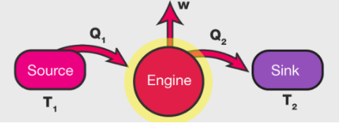
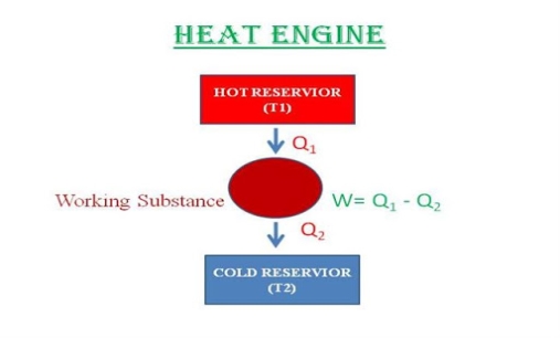
A heat engine is a device that converts heat to work. It takes heat from a reservoir then does some work like moving a piston, lifting weight etc and finally discharges some heat energy into the sink. Schematically it can be represented as:
Heat Engine Efficiency
Let us derive an expression for the efficiency of a heat engine. We can define heat engine efficiency as:
η =W/Q1
Where,
W= Work done by the engine
Q1 = Heat taken from the source
After each cycle, the engine returns to its initial state so,
ΔU =0.
So, from the figure, it is clear that,
W = Q1−Q2
Hence the heat engine efficiency is:
η =Q1−Q2/Q1
η = 1−Q2/Q1
So, for Q2 = 0
Efficiency will be 100% but, in actual, this is not possible because there will be some loss of energy in the system. Hence, for every engine, there is a limit for its efficiency. The efficiency is maximum for a reversible engine such as Carnot heat engine.
Types of Heat Engine
Following are the two types of heat engine:
- Internal combustion engine
- External combustion engine
External combustion engine
In these heat engines, the fuel burns outside and away from the main engine where force and motion are produced. A steam engine is an example of external combustion engine.
Internal combustion engine
In these heat engines, the fuel burns inside the cylinder. A car engine is an example of internal combustion engine.
The internal combustion engine is more efficient than external combustion engine as there is no energy wasted during heat transfer between the boiler and the cylinder.
Heat Engine Cycle
A heat engine typically uses energy provided in the form of heat to do work and then exhausts the heat which cannot be used to do work. Thermodynamics is the study of the relationships between heat and work. The first law and second law of thermodynamics constrain the operation of a heat engine. The first law is the application of conservation of energy to the system, and the second sets limits on the possible efficiency of the machine and determines the direction of energy flow.
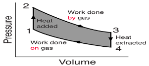
Pressure-Volume (PV) diagrams are a primary visualization tool for the study of heat engines. Since the engines usually involve a gas as a working substance, the ideal gas law relates the PV diagram to the temperature so that the three essential state variables for the gas can be tracked through the engine cycle. Since work is done only when the volume of the gas changes, the diagram gives a visual interpretation of work done. Since the internal energy of an ideal gas depends upon its temperature, the PV diagram along with the temperatures calculated from the ideal gas law determine the changes in the internal energy of the gas so that the amount of heat added can be evaluated from the first law of thermodynamics. In summary, the PV diagram provides the framework for the analysis of any heat engine which uses a gas as a working substance.
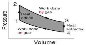
For a cyclic heat engine process, the PV diagram will be a closed loop. The area inside the loop is a representation of the amount of work done during a cycle. Some idea of the relative efficiency of an engine cycle can be obtained by comparing its PV diagram with that of a Carnot cycle, the most efficient kind of heat engine cycle.
A heat engine is a device that converts the energy locked in fuel into force and motion. Fuels like coal, gasoline, natural gas, wood, and peat when burnt in an engine, release the energy it contains to power factory machinery and locomotives. As engines work by burning fuels to release heat, they are called heat engines. Hence, heat engine can be defined as,
An engine that converts the chemical energy of the fuel into thermal energy which is utilised to do useful work
Heat engines are categorized into two types as follows: external combustion engine and internal combustion engine. In the next section, let us look at the two types in detail.
Types of Heat Engine
As discussed, heat engines are classified into two main types as,
Internal Combustion Engines
This process includes the combustion of a fuel that takes place within the system. These types of engines take place where the fuel is burnt in the engine or where the fossil fuel combustion occurs. Pistons are mostly used in the internal combustion type of heat engines. These pistons move up and down within the cylinders that are present in the heat engines. When a single motion of a piston move in the upward or downward direction inside the cylinder is known as the stroke For Example Mostly Cars have four-stroke internal combustion heat engines that consist of an Intake stroke, power stroke, combustion stroke, and exhaust stroke.
External Combustion Engines
These types of heat engines take where the fuel is burnt outside the engine or where the fuel combustion occurs outside the engine. It is a heat engine where a working fluid is included internally and heated by combustion in an external source through the engine wall. This fluid then produced motion and usable work by expanding and acting on the mechanism of the engine.
Parts of Heat Energy
Heat energy is composed of three parts:
- Working object
- Source of heat at high temperature
- Sink of heat at a lower temperature
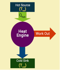
A basic heat engine consists of a gas confined by the piston in a cylinder. When the gas is heated, it expands and moves the piston. This wouldn’t be possible in a practical engine because the motion stops once the gas reaches equilibrium. A practical engine goes through cycles in which the piston moves back and forth. When the gas gets heated, the piston moves upwards and when it is cooled it moves downward. A cycle of heating and cooling is necessary to make the piston move forward and backward.
In a full cycle of heat engine, three things happen as follows:
- Heat is added at a relatively high temperature; hence it can be called QH
- Some part of the added energy is used to perform work
- The unused energy is removed at a relatively cold temperature QC
The diagram below is a representation of heat showing the energy flow.
An important measure of a heat engine is its efficiency. The efficiency of a heat engine depends on the ratio of the work obtained to the heat energy in the high temperature i.e. e = W/Q high. The maximum possible efficiency e max of an engine is
emax =Wmax/Qhigh = (1 – Tlow / Thigh) = (Thigh – Tlow)/Thigh
A Carnot engine or Carnot heat engine is an idealised engine whose working is perfectly reversible. This engine uses an ideal gas as the working substance and performs a 4-stroke process to complete one cycle.
It takes heat Q1 from source and rejects heat Q2 to sink and performing an amount of work W=Q1−Q2
The Carnot's engine is a reversible engine working between two temperature limits.
The complete cycle functions are given below
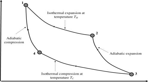
1) Reversible Isothermal expansion heat addition at the constant temperature T1 or TH
2) Reversible Adiabatic expansion of ideal gas. In this process, the temperature of the ideal gas falls from source temperature T1 to sink temperature T2.
3) Reversible Isothermal compression of ideal gas at sink temperature T2 or TC. In doing so, it rejects heat Q2 to the sink.
4) Reversible Adiabatic compression of ideal gas where the temperature naturally raises from T2 to T1 and thus the working substance returns to its original state completing the cycle.
The efficiency is given as
η= Work done / Heat input
Thus, W=Q1−Q2 and heat input is obviously Q1
This gives, η= W/Q1
=1−Q2/Q1
It may be shown thermodynamically that Q2/Q1 = T2/T1.
The Rankine cycle is the fundamental operating cycle of all power plants where an operating fluid is continuously evaporated and condensed. The selection of operating fluid depends mainly on the available temperature range. Figure 1 show the idealized Rankine cycle.
The pressure-enthalpy (p-h) and temperature-entropy (T-s) diagrams of this cycle are given in Figure 2. The Rankine cycle operates in the following steps:
- 1-2-3 Isobaric Heat Transfer. High pressure liquid enters the boiler from the feed pump (1) and is heated to the saturation temperature (2). Further addition of energy causes evaporation of the liquid until it is fully converted to saturated steam.
- 3-4 Isentropic Expansion. The vapor is expanded in the turbine, thus producing work which may be converted to electricity. In practice, the expansion is limited by the temperature of the cooling medium and by the erosion of the turbine blades by liquid entrainment in the vapor stream as the process moves further into the two-phase region. Exit vapor qualities should be greater than 90%.
- 4-5 Isobaric Heat Rejection. The vapor-liquid mixture leaving the turbine (4) is condensed at low pressure, usually in a surface condenser using cooling water. In well designed and maintained condensers, the pressure of the vapor is well below atmospheric pressure, approaching the saturation pressure of the operating fluid at the cooling water temperature.
- 5-1 Isentropic Compression. The pressure of the condensate is raised in the feed pump. Because of the low specific volume of liquids, the pump work is relatively small and often neglected in thermodynamic calculations
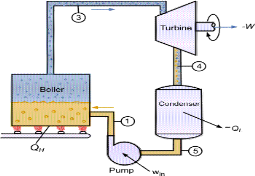 Figure 1 Rankine cycle.
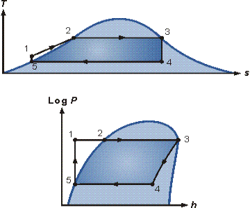
Figure 2. T-s and p-h diagrams.
The efficiency of power cycles is defined as
(1)

Values of heat and work can be determined by applying the First Law of Thermodynamics to each step. The steam quality x at the turbine outlet is determined from the assumption of isentropic expansion, i.e.,
(2)

Where  is the entropy of vapor and Si* the entropy of liquid?
Inefficiencies of Real Rankine Cycles
The efficiency of the ideal Rankine cycle as described in the previous section is close to the Carnot efficiency (see Carnot Cycle). In real plants, each stage of the Rankine cycle is associated with irreversible processes, reducing the overall efficiency. Turbine and pump irreversibility’s can be included in the calculation of the overall cycle efficiency by defining turbine efficiency according to Figure 3

Where subscript act indicates actual values and subscript is indicates isentropic values and a pump efficiency
(4)

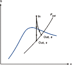
Figure 3 Turbine efficiency.
If ηt and ηp are known, the actual enthalpy after the compression and expansion steps can be determined from the values for the isentropic processes. The turbine efficiency directly reduces the work produced in the turbine and, therefore the overall efficiency. The inefficiency of the pump increases the enthalpy of the liquid leaving the pump and, therefore, reduces the amount of energy required to evaporate the liquid. However, the energy to drive the pump is usually more expensive than the energy to feed the boiler.
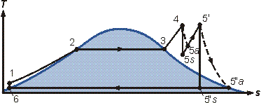
Figure 4 Rankine cycle with vapor superheating.
Even the most sophisticated boilers transform only 40% of the fuel energy into useable steam energy. There are two main reasons for this wastage:
- The combustion gas temperatures are between 1000°C and 2000°C, which is considerably higher than the highest vapor temperatures. The transfer of heat across a large temperature difference increases the entropy.
- Combustion (oxidation) at technically feasible temperatures is highly irreversible.
Since the heat transfer surface in the condenser has a finite value, the condensation will occur at a temperature higher than the temperature of the cooling medium. Again, heat transfer occurs across a temperature difference, causing the generation of entropy. The deposition of dirt in condensers during operation with cooling water reduces the efficiency.
OTTO CYCLE: Otto cycle is a thermodynamic cycle upon which a spark ignition engine works. Spark Ignition (or SI) engine uses petrol (or Gasoline) as fuel. Otto cycle was invented by Nicolas Otto in 1876.
Spark ignition engine is a type of internal combustion engines.
Below are P-V and T-S Diagrams of the Otto Cycle.
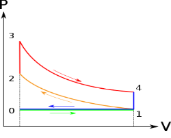
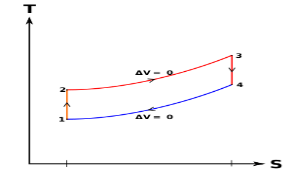
Otto Cycle is comprised of four processes (apart from the intake and exhaust process)
Process 1-2: This process comes after intake process. In case of SI engines, intake is a mixture of gasoline and air, also known as charge. In this process charge is compressed in isentropic manner. Temperature raised from T1 to T2 and volume decrease from V1 to V2.
Process 2-3: In this process the fuel gets blasted with the help of external spark (that is why the engine is known as spark ignition engine). This process is a constant volume heat addition process. Temperature raised from T2 to T3
.
Q2-3= CV(T3-T2)
Process 3-4: After the combustion process, the exhaust gases expend. This process is an isentropic expansion process. No heat is interchanged. The temperature fall from T3 to T4 and volume increase from V3 to V4.
Process 4-1: After the expansion process, exhaust valve opens. This results into sudden drop of pressure inside engine cylinder. This process is a constant volume heat rejection process.
Q4-1= CV(T4-T1)
Process 0-1 is the intake process and process 1-0 is the exhaust process.
Efficiency of the Otto Cycle is the ratio of work output to the heat input.
Work done or output = Heat Supply-Heat rejected
Work output = [CV (T3-T2)] – [CV (T4-T1)]
Heat Input = CV (T3-T2)
Efficiency = Work done / Heat Input
After putting values of heat input and work output in the above formula, we get
η = [CV (T3-T2)] – [CV (T4-T1)] / CV (T3-T2)
η = 1 – [(T4-T1)/ (T3-T2)]
η = 1 – [T1 (T4 / T1 – 1 )/ T2 (T3/T2 - 1)]
r = compression ratio = V1 / V2 = V4 / V3
T2 = T1 (V1/V2) y-1
T2 = T1 (r) y-1 ...equation 1
T3/T4 = (V4 /V3)y-1
T3 = T4 (r) y-1 ……equation 2
From equation 1 and 2
T2 / T1 = T3/T4
Or T4 / T1 = T3 / T2
Put the value in this equation
η = 1 – [T1 (T4 / T1 – 1)/ T2 (T3/T2 - 1)]
We get
η = 1 – [T1 / T2]
Or η = 1 – 1 / (r )y-1
DIESEL CYCLE
Diesel cycle is a gas power cycle invented by Rudolph Diesel in the year 1897. It is widely used in diesel engines.
Diesel cycle is similar to Otto cycle except in the fact that it has one constant pressure process instead of a constant volume process (in Otto cycle).
Diesel cycle can be understood well if you refer its p-V and T-s diagrams.
P-V and T-s Diagrams of Diesel Cycle:
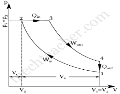
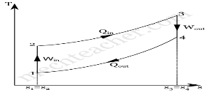
p-V Diagram T-s Diagram
Processes in Diesel Cycle:
Diesel cycle has four processes. They are:
- Process 1-2: Isentropic (Reversible adiabatic) Compression
- Process 2-3: Constant Pressure (Isobaric) Heat Addition
- Process 3-4: Isentropic Expansion
- Process 4-1: Constant Volume (Isochoric) Heat Rejection
Process 1-2: Isentropic Compression
In this process, the piston moves from Bottom Dead Centre (BDC) to Top Dead Centre (TDC) position. Air is compressed isentropically inside the cylinder. Pressure of air increases from p1 to p2, temperature increases from T1 to T2, and volume decreases from V1 to V2. Entropy remains constant (i.e., s1 = s2). Work is done on the system in this process (denoted by Win in the diagrams above).
Process 2-3: Constant Pressure Heat Addition
In this process, heat is added at constant pressure from an external heat source. Volume increases from V2 to V3, temperature increases from T2 to T3 and entropy increases from s2 to s3.
Heat added in process 2-3 is given by
Qin = mCP (T3 − T2) kJ ………… (i)
Where,
m → Mass of air in kg
Cp → Specific heat at constant pressure in kJ/kg K
T2 → Temperature at point 2 in K
T3 → Temperature at point 3 in K
Process 3-4: Isentropic Expansion
Here the compressed and heated air is expanded isentropically inside the cylinder. The piston is forced from TDC to BDC in the cylinder. Pressure of air decreases from p3 to p4, temperature decreases from T3 to T4, and volume increases from V3 to V4. Entropy remains constant (i.e., s3 = s4). Work is done by the system in this process (denoted by Wout in the p-V and T-s diagrams above).
Process 4-1: Constant Volume Heat Rejection
In this process, heat is rejected at constant volume (V4 = V1). Pressure decreases from P4 to P1, temperature decreases from T4 to T1 and entropy decreases from s4 to s1.
Heat rejected in process 4-1 is given by
Qout = mCv (T4 − T1) kJ ………… (ii)
Where,
m → Mass of air in kg
Cv → Specific heat at constant volume in kJ/kgK
T2 → Temperature at point 2 in K
T3 → Temperature at point 3 in K
Air-standard Efficiency of Diesel Cycle:
Air-standard efficiency (or thermal efficiency) of diesel cycle is given by:
ηTh= ηDiesel= Heat Added – Heat Rejected / HeatAdded×100%
ηDiesel=Qin−Qout / Qin×100%
From equations (i) and (ii)
ηDiesel= mCp(T3–T2)– mCV(T4–T1) / mCp (T3–T2)×100%
ηDiesel = (1−mCV (T4−T1) / mCp (T3−T2))×100%
ηDiesel = (1−CV (T4−T1)/ Cp (T3−T2))×100%
ηDiesel = (1−1 / γ (T4−T1) / (T3−T2))×100% (Since Cp / CV= γ
CV / Cp=1/γ