UNIT 1
Introduction to Engineering Graphics
To record information on paper (or another surface), instruments and equipment are required. Even for drawings made freehand, pencils, erasers, and sometimes coordinate paper or other special items are used. The lines made on drawings are straight or curved (including circles and arcs). They are made with drawing instruments, which are the necessary tools for laying down lines on a drawing in an accurate and efficient manner. To position the lines, a measuring device, a scale, is needed.
The various instruments will be described in detail later, but the opening of this chapter will serve as an introduction. To draw straight lines, the T square, with its straight blade and perpendicular head, or a triangle is used to support the stroke of the pencil. To draw circles, a compass is needed. In addition to the compass, the draftsman needs dividers for spacing distances and a small bow compass for drawing small circles. To draw curved lines other than circles, a French curve is required. A scale is used for making measurements.
- Drawing Paper
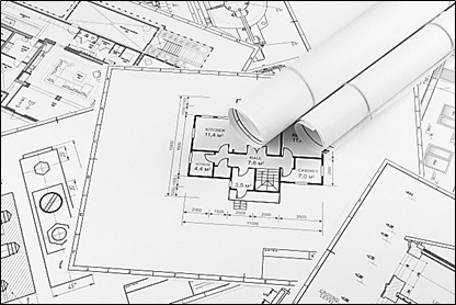
Drawing paper is made up of variety of qualities and manufactured in sheets or rolls. White drawing papers that will not turn yellow with age or exposure are used for finished drawings, maps, charts, and drawings for photographic reproduction. For pencil layouts and working drawings buff detail papers are preferred as they are easier on the eyes compared to white papers.
- Tracing Paper
Tracing papers are thin papers, natural or transparent, on which drawings are traced, in pencil or ink, and from which blueprints or similar contact prints can be made. In most drafting rooms original drawings are pencilled on tracing papers, and blueprints are made directly from these drawings, a practice increasingly successful because of improvements both in papers and in printing.
- Thumbtacks
The best thumbtacks are made with thin heads and steel points screwed into them. Cheaper ones are made by stamping. Use tacks with tapering pins of small diameter and avoid flat-headed (often coloured) map pins, as the heads are too thick and the pins rather large.

- Pencils
The basic instrument is the graphite lead pencil, made in various hardness’s. Each manufacturer has special methods of processing design to make the lead strong and yet give a smooth clear line.
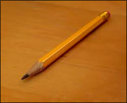
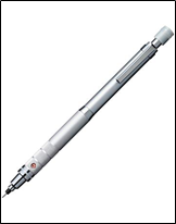
In the left there is an ordinary pencil, with the lead set in wood and the other is a semi-automatic pencil with thinner leads. Both are fine but have the disadvantage that in use, the wood must be cut away to expose the lead (a time-consuming job), and the pencil becomes shorter and shorter until the last portion of it is to be discarded. Whereas semiautomatic pencils, with a chuck to clamp and hold the lead, are more convenient, has a plastic handle and changeable tip (for indicating the grade of lead).
Drawing pencils are graded by numbers and letters from 6B which is very soft and black, to 5B, 4B, 3B, 2B, B, and HB to F, the medium grade; then H, 2H, 3H, 4H, 5H, 6H, 7H, and 8H to 9H, the hardest. The soft (B) grades are used primarily for sketching and rendered drawings and the hard (H) grades for instrument drawings.
- Pencil Pointer
After the wood of the ordinary pencil is cut away with a pocketknife or mechanical sharpener, the lead must be formed to a long, conic point.
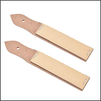
A pencil pointer is a tool for sharpening a pencil’s writing point by shaving away its worn surface.
- Erasers
The Ruby pencil eraser, large size with bevelled ends, is the standard. This eraser not only removes pencil lines effectively but is better for ink, as it removes ink without seriously damaging the surface of paper or cloth.
Art gum or a soft-rubber eraser, is useful for cleaning paper and cloth of finger marks and smears that spoil the appearance of the completed drawing.
- Penholders and Pens
The penholder should have a grip of medium size, small enough to enter the mouth of a drawing-inkbottle easily yet not so small as to cramp the fingers while in use. A size slightly larger than the diameterof a pencil is good.
- Triangles
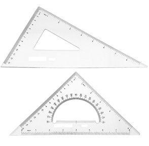
Triangles, are made of transparent hard or other plastic material. Through internal strains they sometimes lose their accuracy. Triangles should be kept flat to prevent warping. For ordinary work, a 6- or 8-in. 45° and a 10-in. 30-60° are good sizes.
- The T Squares
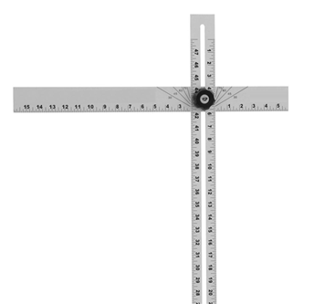
The fixed-head T square, is used for all ordinary work. It should be of hardwood, and the blade should be perfectly straight. The transparent-edged blade is much the best. A draftsman will have several fixed-head squares of different lengths and will find an adjustable-head square of occasional use.
- Scales
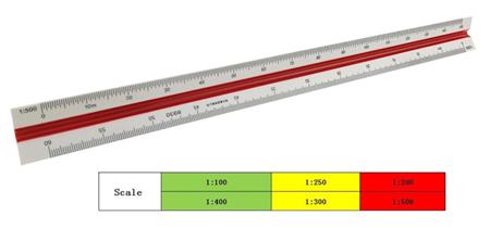
Scales, are made in various number of graduations to meet the requirements of many kinds of work. For convenience, scales are classified according to their most-common uses.
Mechanical Engineer’s Scale
These are divided and numbered in such a way that fractions of inches represent inches. The most common ranges are 1/8, 1/4, 1/2, and 1 in. To the inch. These scales are known as the size scales because the reduced size also represents the ratio of size, as for example one-eighth size.
Mechanical engineer's scales are almost always "full divided"; that is, the smallest divisions run throughout the entire length.
They are generally graduated with the marked divisions numbered from right to left, as well as from left to right, as shown in Figure Mechanical engineer's scales are used mostly for drawings of machine parts and small structures where the drawing size is more than one-eighth the size of the actual object.
Civil Engineer’s Scale
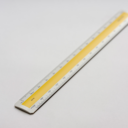
These are divided into decimals with divisions ranging from 10, 20, 30, 40, 50, 60, and 80 to the inch. Such a scale is usually full divided and is sometimes numbered both from left to right and right to left. Civil engineer's scales are most used for plotting and drawing maps, although they are convenient for any work where divisions of the inch in tenths is required.
Metric Scales
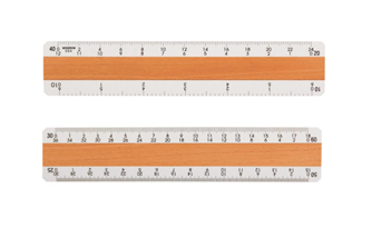
Metric scales are supplied in all the styles and sizes and materials of other scales. They are usually full-divided and are numbered in meters, centimetres, or millimetres depending upon the reduction in size. Typical size reductions are: 1:1, 1:2, 1:5, 1:10, 1:20, 1:25, 1:33.3, 1:50, 1:75, 1:80, 1: 100, 1: 150. Also available are metric equivalent scales for direct conversion of English scales.
- Curves
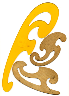
Curve rulers, called "irregular curves" or "French curves," are used to draw curved lines other than circular arcs. The patterns for these curves are laid out in parts of ellipse and spirals or other mathematical curves in various combinations. For the student, one ellipse curve of the general shape or one spiral, either a logarithmic spiral is a useful small curve.
- Case Instruments
We have so far, except for curves considered only the instruments needed for drawing straight lines. A major portion of any drawing is likely to be circles and circle arcs, and the so called “case” instruments are used for these.
Divider:
It is used for laying off or transferring measurements.
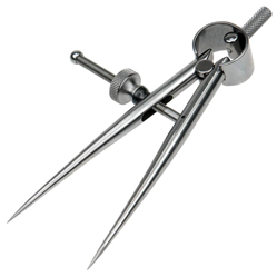
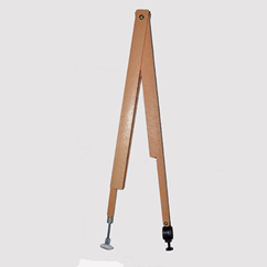
Next is the large compass with lengthening bar and pen attachment. The three “bow” instruments are for smaller work. They are almost always made without the conversion feature.
The ruling pen is used for inking straight lines.
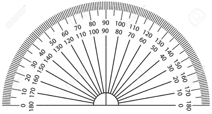
Protractor is used to measure angles upto 180°.
- Cautions in the use of Instruments
- Scales are not to be used as a ruler for drawing lines.
- Horizontal lines with the lower edge should not be drawn with a T square.
- The lower edge of T square should not be used as a base for drawing triangles.
- T square is not to be used as hammer.
- Never put either end of a pencil into the mouth.
- Never sharpen a pencil over a drawing board.
- Never oil the joints of compasses.
- Never begin work without wiping off the table and instruments.
- Never work on a table cluttered with unneeded instruments or equipment’s.
- Never fold a drawing or a tracing.
Lettering
Graphic representation of the shape of a part, machine, or structure gives one aspect of the information needed for its construction. To this must be added, to complete the description, figured dimensions, notes on material and finish, and a descriptive title—all lettered, freehand, in a style that is perfectly legible, uniform, and capable of rapid execution. As far as the appearance of a drawing is concerned, the lettering is the most important part. But the usefulness of a drawing, too, can be ruined by lettering done ignorantly or carelessly, because illegible figures are apt to cause mistakes in the work.
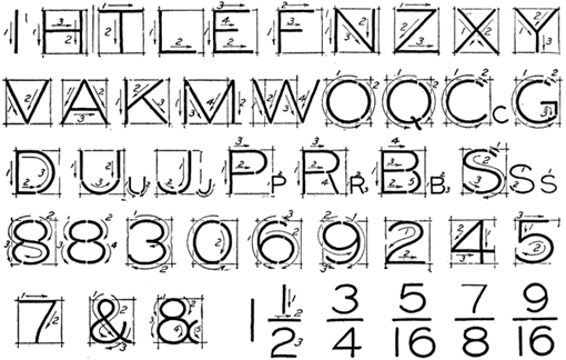
By far the greatest amount of lettering on drawings is done in a rapid single-stroke letter, either vertical or inclined, and every engineer must have absolute command of these styles.
The term "single-stroke," or "one-stroke," does not mean that the entire letter is made without lifting the pencil or pen but that the width of the stroke of the pencil or pen is the width of the stem of the letter.
Single Stroke lettering
By far the greatest amount of lettering on drawings is done in a rapid single-stroke letter, either vertical or inclined, and every engineer must have absolute command of these styles.
The term "single-stroke," or "one-stroke," does not mean that the entire letter is made without lifting the pencil or pen but that the width of the stroke of the pencil or pen is the width of the stem of the letter.
Guidelines
Always draw light guide lines for both tops and bottoms of letters, using a sharp pencil. Figure 1 shows a method of laying off several equally spaced lines. Draw the first base line; then set the bow spacers to the distance wanted between base lines and step off the required number of base lines. Above the last line mark the desired height of the letters.
Lettering in Pencil
Good technique is as essential in lettering as in drawing. The quality of the lettering is important whether it appears on finished work to be reproduced by one of the printing processes or as part of a pencil drawing to be inked. In the first case, the penciling must be clean, firm, and opaque; in the second, it may be lighter.
Single - stroke Vertical Capitals:
The vertical, single-stroke, commercial Gothic letter is a standard for titles, reference letters, etc. As for the proportion of width to height, the general rule is that the smaller the letters are, the more extended they should be in width.
A low extended letter is more legible than a high compressed one and at the same time makes a better appearance.
Vertical lower-case letters:
The single-stroke, vertical lower-case letter is not commonly used on machine drawings but is used extensively in map drawing. It is the standard letter for hypsography in government topographic drawing. The bodies are made two-thirds the height of the capitals with the ascenders extending to the capital line and the descenders dropping the same distance below.
Single strokes Inclined capitals:
Many draftsmen use the inclined, or slant, letter in preference to the upright. The order and direction of strokes are the same as in the vertical form.
Single stroke, Inclined lower-case letters:
The inclined lower-case letters have bodies two-thirds the height of the capitals with the ascenders extending to the capital line and the descenders dropping the same distance below the base line. The lower-case letter is suitable for notes and statements on drawings because it is much more easily read than all capitals.
The loop letters are made with an ellipse whose long axis is inclined about 45° in combination with a straight line.
Plain scales: A plain scale consists of a line divided into suitable number of
Equal parts or units, the first of which is sub-divided into smaller parts. Plain scales
Represent either two units or a unit and its sub-division.
In every scale,
(i) The zero should be placed at the end of the first main division, i.e. between
The unit and its sub-divisions.
(ii) From the zero mark, the units should be numbered to the right and its
Sub-divisions to the left.
(iii) The names of the units and the sub-divisions should be stated clearly below or at the respective ends.
(iv) The name of the scale (e.g. Scale, 1: 10) or its R.F. Should be mentioned below the scale.
A diagonal scale is used when very minute distances such as 0.1 mm etc. are to be accurately measured or when measurements are required in three units; for example, dm, cm and mm, or yard, foot, and inch.
Small divisions of short lines are obtained by the principle of diagonal division, as explained below.
Drawings are scaled so that the objects represented can be illustrated
Clearly on standard sizes of paper. It would be difficult,
For example, to make a full-size drawing of a house. You must
Decrease the displayed size, or scale, of the house to fi t properly
On a sheet. Another example is a small machine part that
Requires you to increase the drawing scale to show necessary
Detail. Machine parts are often drawn full size or even two, four,
Or ten times larger than full size, depending on the actual size
Of the part.
The selected scale depends on:
• The actual size of the objects drawn.
• The amount of detail to show.
• The media size.
• The amount of dimensioning and notes required.
A map scale in which figures representing units (as centimetres, inches, or feet) are expressed in the form of the fraction 1/x (as 1/250,000) or of the ratio 1:x to indicate that one unit on the map represents x units (as 250,000 centimetres) on the earth's surface.