UNIT 5
Projections of Planes
When a plane is inclined to a reference plane, its projections may be obtained in
Two stages. In the initial stage, the plane is assumed to be parallel to that reference plane to which it must be made inclined. It is then tilted to the required inclination in the second stage.
(1) Plane, inclined to H.P. And perpendicular to the V.P.: When the
Plane is inclined to the H.P. And perpendicular to the V.P., in the initial stage, it
Is assumed to be parallel to the H.P. Its top view will show the true shape. The
Front view will be a line parallel to xy. The plane is then tilted so that it is inclined
To the H.P. The new front view will be inclined to xy at the true inclination. In
The top view the corners will move along their respective paths (parallel to xy).
1. A regular pentagon of 25 mm side has one side on the ground. Its plane is inclined at 45° to the H.P and perpendicular to the V.P. Draw its projections and show its traces.

Figure 1
(i) Draw the pentagon in the top view with one side perpendicular to xy [fig. 1-(i)]. Project the front view. It will be the line a'c' contained by xy. (ii) Tilt the front view about the point a', so that it makes 45° angle with xy.
(iii) Project the new top view ab1c1d1e upwards from this front view and horizontally from the first top view. It will be more convenient if the front view is reproduced in the new position separately and the top view projected from it, as shown in fig. 1(ii). The V.T. Coincides with the front view and the H.T. Is perpendicular to xy, through the point of intersection between xy and the front view produced.
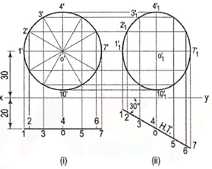
2. Draw the projections of a circle of 50 mm diameter having its plane vertical and inclined at 30° to the V.P. Its centre is 30 mm above the H.P. And 20 mm in front of the V.P. Show also its traces.

Figure 2
A circle has no corners to project one view from another. However, a number of
Points, say twelve, equal distances apart, may be marked on its circumference.
(i) Assuming the circle to be parallel to the V.P., draw its projections. The front view will be a circle [fig. 2 (i)], having its centre 30 mm above xy. The top view will be a line, parallel to and 20 mm below xy.
(ii) Divide the circumference into twelve equal parts (with a 30°-60° set-square) and mark the points as shown. Project these points in the top view. The centre O will coincide with the point 4.
Iii) When the circle is tilted, so as to make 30° angle with the V.P., its top view will become inclined at 30° to xy. In the front view all the points will move along their respective paths (parallel to xy). Reproduce the top view keeping the centre o at the same distance, viz. 20 mm from xy and inclined at 30° to xy [fig. 2 (ii)].
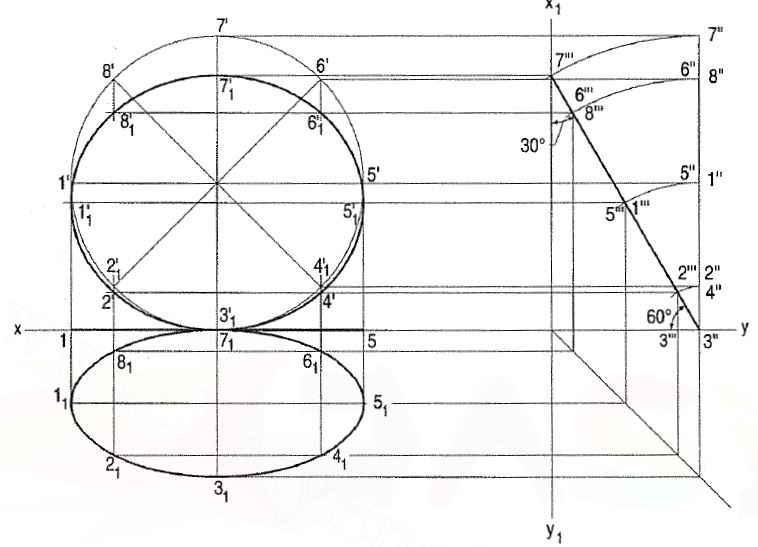
3. A thin circular plate of 70 mm diameter is resting on its circumference such that its plane is inclined 60° to the H.P. And 30° to the V.P. Draw the projections of the plate.

Figure 3
(i) Draw the projection of the plate keeping its plane parallel to the V.P. As shown in fig. 3.
(ii) Mark a reference line x1y1 perpendicular to xy line to represent the auxiliary
Plane which is at right angle to both the H.P. And the V.P.
(iii) Divide the front view in eight parts and mark the points 1 ', 2' .... 8'. Project these points on the side view as 1 ", 2" .... 8".
(iv) Tilt the side view 3" 7" such that it touches the x1y1 line and makes 60° with the xy line.
(v) Complete the projection as shown in fig. 3
Projections of lines and planes at given inclinations to one or both the planes may also be obtained by the use of auxiliary planes. The method adopted is called the alteration or change-of-reference-line method.
The line, in its initial position, is assumed to be parallel to both the planes of projection. Then, instead of making the line inclined to one of the planes, an auxiliary plane inclined to the line is assumed, i.e. a new reference line is drawn and the view is projected on it.
In case of a plane, it is kept parallel to one of the planes of projection in the initial stage, the required views being obtained by projecting it on new reference lines.
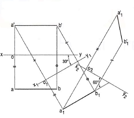
Q. A line AB, 50 mm long, is inclined at 30° to the H.P. And its top view makes an angle of 60° with the V.P. Draw its projections.

(i) Draw the projections ab and a'b', assuming AB to be parallel to both the planes.
(ii) Project a new top view a1b1 on a new reference line x1y1 inclined at 30° to a'b'. a1b1 is still parallel to x1y1.
(iii) Draw another reference line x2y2 to represent an A.V.P. Inclined at 60° to the top view a1b1.
(iv) Project the required front views a'1b'1 on x2y2• Note that a1o1 = ao, a'1o2 = a'o1 etc.
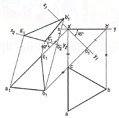
Q. An equilateral triangle of 40 mm long sides has an edge on the ground and inclined at 60° to the V.P. Its plane makes an angle of 45° with the H.P. Draw its projections.

(i) Draw the top view abc and the front view a'b', assuming the triangle to be lying on the ground and one side perpendicular to the V.P.
(ii) Draw x1y1 inclined at 45° to a'b' (the front view) and passing through a' (because the triangle has its edge on the ground).
(iii) Project the new top view a1b1c1 . Again draw a new reference line x2y2 inclined at 60° to the line a1c1 (which is to make 60° angle with the V.P.).
(iv) Project the final front view a'1b'1c'1 on x2y2. Note that a'1c'1 is in x2y2.