Unit 8
Pumps
Content:
Reciprocating pumps:
Reciprocating pump is a positive displacement pump where certain volume of liquid is collected in enclosed volume and is discharged using pressure to the required application. Reciprocating pumps are more suitable for low volumes of flow at high pressures.
It is very important part of the ships machinery and any other industry which is present in the world. High pressure is the main characteristic of this pump and this high pressure output are being used in places like starting of the engine or you can say the building of pressure in the fluids.
But there are used in limited application because they require lot of maintenance. These pumps are positive displacements pumps and that is the reason they do not require any type of priming for their functioning in the starting period of the pump.
Parts of Reciprocating Pump:
The Parts of Reciprocating Pump are as follows.
- Water Sump
- Strainer
- Suction Pipe
- Suction Valve
- Cylinder
- Piston and Piston rod
- Crank and Connecting rod
- Delivery valve
- Delivery pipe
The explanation for the parts of Reciprocating pump are as follows.
- Water Sump:
It is the source of water. From the sump, water is to be transported to the delivery pipes by the usage of the piston.
II. Strainer:
It acts as a mesh that can screen all the dirt, dust particles, etc. from the sump. If there is no strainer, then the dirt or dust also enters into the cylinder which can jam the region and affects the working of the pump.
III. Suction Pipe:
The main function of the suction pipe is to collect the water from the sump and send it to the cylinder via a suction valve. The suction pipe connects the water sump and the cylinder.
IV. Suction Valve:
It is a non-return valve which means it can take the fluid from the suction pipe and send it to the cylinder but cannot reverse the water back to it. In the sense, the flow is unidirectional.
This valve opens only during the suction of fluid and closes when there is a discharge of fluid to outside.
V. Cylinder:
It is a hollow cylinder made of cast iron or steel alloy and it consists of the arrangement of piston and piston rod.
VI. Piston and Piston rod:
For suction, the piston moves back inside the cylinder and for discharging of fluid, the piston moves in the forward direction.
The Piston rod helps the piston to move in a linear direction i.e. either the forward or the backward directions.
VII. Crank and Connecting rod:
For rotation, the crank is connected to the power source like engine, motor, etc. whereas the connecting rod acts as an intermediate between the crank and piston for the conversion of rotary motion into linear motion.
VIII. Delivery Pipe:
The function of the delivery pipe is to deliver the water to the desired location from the cylinder.
IX. Delivery valve:
Similar to the suction valve, a delivery valve is also a Non-return valve. During suction, the delivery valve closes because the suction valve is in opening condition and during Discharge, the suction valve is closed and the delivery valve Is opened to transfer the fluid.
Working Principle of Reciprocating Pump:
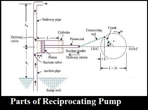
When the power supply is given to the reciprocating pump, the crank rotates through an electric motor. The angle made by the crank is responsible for the movement of the piston inside the cylinder. By referring to the above diagram, the piston moves towards the extreme left of the cylinder when the crank meets position A i.e. θ=0.
Similarly, the piston moves towards the extreme right of the cylinder when the crank meets the position C i.e. θ=180.
A partial vacuum in the cylinder takes place when the piston movement is towards the right extreme position i.e. (θ=0 to θ=180.) and that makes the liquid enter into the suction pipe. This is due to the presence of atmospheric pressure on the sump liquid which is quite less than the pressure inside the cylinder. Therefore, due to the difference in pressure, the water enters into the cylinder through a non-return valve.
The water which stays in the volume of the cylinder has to be sent to the discharge pipe via discharge valve and this can be done when the crank is rotating from C to A i.e. (θ=180 to θ=360) which moves the piston in the forward direction. Due to the movement of the piston in a forward direction, the pressure increases inside the cylinder which is greater than the atmospheric pressure.
This results in the opening of the delivery valve and closing of the suction valve. Once the water comes into the delivery valve, it cannot move back to the cylinder because it is a unidirectional valve or non-return valve.
From there, it enters into the delivery pipe so that it can be sent to the required position. Therefore, in this way, the water is sucked and discharged from the sump to the desired location through the piston inside the cylinder.
Reciprocating Pump Advantages:
1) This pump is self-priming – Not require filling the cylinders by starting.
2) This pump can work in wide pressure range.
3) Priming is not necessary in pump.
4) Provide elevated suction lift.
5) They are used for air also.
6) No priming is needed in the Reciprocating pump compared to the Centrifugal pump.
7) It can deliver liquid at high pressure from the sump to the desired height.
8) It exhibits a continuous rate of discharge.
9) It can work due to the linear movement of piston whereas the centrifugal pump works on the rotary velocity of the impeller.
Reciprocating Pump Disadvantages:
1. Flow is not consistent, so we have to fit a bottle at equally ends.
2. Flow is extremely less and cannot use for high flow process.
3. High wear and tear, so need lot maintenance.
4. Early price is much more in this pump.
5. Additional heavy and large in shape.
6. Low discharging capacity
7. The maintenance cost is very high due to the presence of a large number of parts.
8. The initial cost of this pump is high.
9. Viscous fluids are difficult to pump.
Applications of Reciprocating Pump:
The applications of Reciprocating Pump are as follows.
- Gas industries
- Petrochemical industries
- Oil refineries
- Vehicle water servicing centres etc.
- Oil drilling operations
- Pneumatic pressure systems
- Light oil pumping
- Feeding small boilers condensate return.
Centrifugal pump:
Centrifugal pump is a hydraulic machine which converts mechanical energy into hydraulic energy by the use of centrifugal force acting on the fluid. These are the most popular and commonly used type of pumps for the transfer of fluids from low level to high level. It is used in places like agriculture, municipal (water and wastewater plants), industrial, power generation plants, petroleum, mining, chemical, pharmaceutical and many others.
Pumps are the mechanical devices that convert mechanical energy into hydraulic energy. They are generally used to raise the water or other fluids from lower elevation to higher elevation. So, pumps are generally classified into centrifugal pump and positive displacement pump. Centrifugal pumps are non- positive displacement pumps. They work on the principle of centrifugal action.
The Main parts of Centrifugal Pump are:
1. Impeller
It is a wheel or rotor which is provided with a series of backward curved blades or vanes. It is mounded on the shaft which is coupled to an external source of energy which imparts the liquid energy to the impeller there by making it to rotate.
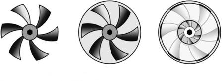
Fig 2: Open, Semi Enclosed and Enclosed Impeller.
Impellers are divided into following types,:
a) Based on direction of flow:
1) Axial-flow: – the fluid maintains significant axial-flow direction components from the inlet to outlet of the rotor.
2) Radial-flow: – the flow across the blades involves a substantial radial-flow component at the rotor inlet, outlet and both.
3) Mixed-flow: – there may be significant axial and radial flow velocity components for the flow through the rotor row.
b) Based on suction type:
1) Single suction: – liquid inlet on one side.
2) Double suction: – liquid inlet to the impeller symmetrically from both sides.
c) Based on mechanical construction:
1) Closed: – shrouds or sidewall is enclosing the vanes.
2) Open: – no shrouds or wall to enclose the vanes.
3) Semi–open or vortex type.
2. Casing
It is a pipe which is connected at the upper end to the inlet of the pump to the centre of impeller which is commonly known as eye. The double end reaction pump consists of two suction pipe connected to the eye from both sides. The lower end dips into liquid in to lift. The lower end is fitted in to foot valve and strainer.
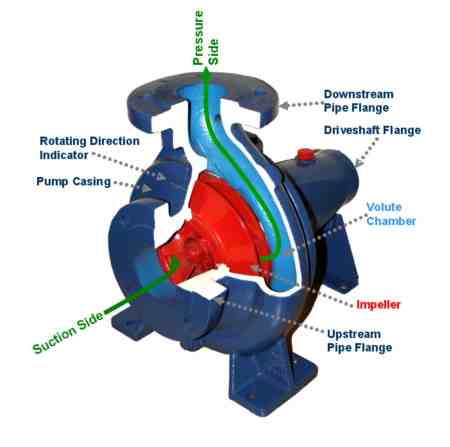
Fig 3: Main Components of Centrifugal Pump.
Commonly three types of casing are used in centrifugal pump are –
1) Volute casing: – It is spiral type of casing in which area of flow increase gradually. The increase in area of flow decreases the velocity of flow and increases the pressure of water.
2) Vortex casing: – if a circular chamber is introduced between casing and the impeller, the casing is known as vortex casing.
3) Casing with guide blades: – the impeller is surrounded by a series of guide blades mounted on a ring know as diffuser.
3. Delivery Pipe
It is a pipe which is connected at its lower end to the out let of the pump and it delivers the liquid to the required height. Near the outlet of the pump on the delivery pipe, a valve is provided which controls the flow from the pump into delivery pipe.
4. Suction Pipe with Foot Valve and Strainer
Suction pipe is connected with the inlet of the impeller and the other end is dipped into the sump of water. At the water end, it consists of foot value and strainer. The foot valve is a one way valve that opens in the upward direction. The strainer is used to filter the unwanted particle present in the water to prevent the centrifugal pump from blockage.
Working of Centrifugal Pump:
Water is drawn into the pump from the source of supply through a short length of pipe (suction pipe). Impeller rotates; it spins the liquid sitting in the cavities between the vanes outwards and provides centrifugal acceleration with the kinetic energy.
This kinetic energy of a liquid coming out an impeller is harnessed by creating a resistance to flow. The first resistance is created by the pump volute (casing) that catches the liquid and shows it down.
In the discharge nozzle, the liquid further decelerates and its velocity is converted to pressure according to BERNOULLI’S PRINCIPAL.
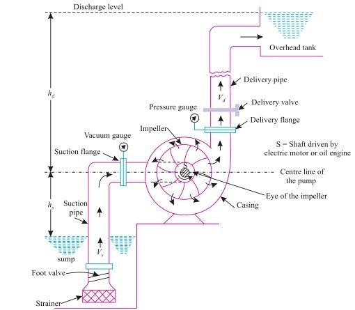
Let us understand in detail, how a Centrifugal pump works. Centrifugal pumps are used to induce flow or raise a liquid from a low level to a high level. These pumps work on a very simple mechanism. A centrifugal pump converts rotational energy, often from a motor, to energy in a moving fluid.
The two main parts that are responsible for the conversion of energy are the impeller and the casing. The impeller is the rotating part of the pump and the casing is the airtight passage which surrounds the impeller. In a centrifugal pump, fluid enters into the casing, falls on the impeller blades at the eye of the impeller, and is whirled tangentially and radially outward until it leaves the impeller into the diffuser part of the casing. While passing through the impeller, the fluid is gaining both velocity and pressure
Efficiency of centrifugal pump:-
The efficiency of a centrifugal pump can be defined as the ratio of the output power (water) to the input power (shaft). It can be demonstrated by using the following equation.
Ef = PW / PS
Where,
Ef is efficiency
Pw is the water power
Ps is the shaft power
Some other efficiency are given below:
- Mechanical efficiency: – It is ratio of the impeller power to the shaft power.
- Hydraulic efficiency: – It is ratio of the manometric head to the Euler head.
- Volumetric efficiency:- It is ratio of the actual to the theoretical discharge.
- Overall efficiency: – It is ratio of the water power to the shaft power.
Applications of Centrifugal Pumps:
The fact that centrifugal pumps are the most popular choice for fluid movement makes them a strong contender for many applications. They are used across numerous industries. Supplying water, boosting pressure, pumping water for domestic requirements, assisting fire protection systems, hot water circulation, sewage drainage and regulating boiler water are among the most common applications. Outlined below are some of the major sectors that make use of these pumps:
- Oil & Energy - pumping crude oil, slurry, mud; used by refineries, power generation plants
- Industrial & Fire Protection Industry - Heating and ventilation, boiler feed applications, air conditioning, pressure boosting, fire protection sprinkler systems.
- Waste Management, Agriculture & Manufacturing - Wastewater processing plants, municipal industry, drainage, gas processing, irrigation, and flood protection
- Pharmaceutical, Chemical & Food Industries - paints, hydrocarbons, petrochemical, cellulose, sugar refining, food and beverage production
- Various industries (Manufacturing, Industrial, Chemicals, Pharmaceutical, Food Production, Aerospace etc.) - for the purposes of cryogenics and refrigerants.
Advantages of Centrifugal Pumps
The centrifugal pumps advantages include the following.
a) These pumps do not include drive seals that reduce leakage risk.
b) These pumps are used to pump out harmful and risky fluids.
c) These pumps have magnetic coupling that can be damaged simply in overload situations as well as protects the pump from external forces.
d) The motor and pump are separated from each other so heat transfer is impossible from the motor to pump.
e) These pumps generate low friction.
Disadvantages of Centrifugal Pumps
The centrifugal pumps disadvantages include the following.
a) The energy loss can be occurred due to the coupling that generates some magnetic resistance.
b) Once the intense load occurs, possibilities are there for the coupling fall.
c) If fluids with ferrous particles are pumped out, then rust occurs & over the time pumps stops working.
d) When the flow of liquid is less through the pump, then the overheating can occur
Rotary Pumps
It is a positive displacement pump. For each revolution of the pump, a fixed volume of fluid is moved regardless of the resistance against which the pump is pushing. It is self-priming, and gives practically constant delivered capacity regardless of the pressure. The rotary pump consists of a fixed casing containing gears, cams, screws, plungers or similar elements actuated by rotation of the drive shaft. A number of pump types are included in this classification, among which are the gear pump, the screw pump, and the rotary vane pump.
Rotary pumps are useful for pumping oil and other liquids of high viscosity. In the engine room, rotary pumps are used for handling lube oil and fuel oil and are suitable for handling liquids over a wide range of viscosities. Rotary pumps are designed with very small clearances between rotating parts and stationary parts to minimize leakage (slippage) from the discharge side back to the suction side. Rotary pumps are designed to operate at relatively low speeds to maintain these clearances. The operation at higher speeds causes erosion and excessive wear which result in increased clearances with a subsequent decrease in pumping capacity. Classification of the rotary pumps is generally based on the types of rotating element.
Gear pump – The simple gear pump has two spur gears that mesh together and revolve in opposite directions. One is the driving gear, and the other is the driven gear. Clearances between the gear teeth (outside diameter of the gear) and the casing and between the end face and the casing are only a few thousandths of an inch. As the gears turn, they unmesh and liquid flows into the pockets that are vacated by the meshing gear teeth. This creates the suction that draws the liquid into the pump. The liquid is then carried along in the pockets formed by the gear teeth and the casing. On the discharge side, the liquid is displaced by the meshing of the gears and forced out through the discharge side of the pump.
Rotary vane pumps – The rotary vane pump has a cylindrically-bored housing with a suction inlet on one side and a discharge outlet on the other side. A rotor (smaller in diameter than the cylinder) is driven about an axis that is placed above the centre line of the cylinder to provide minimum clearance between the rotor and cylinder at the top and maximum clearance at the bottom. The rotor carries vanes (which move in and out as the rotor rotates) to maintain sealed spaces between the rotor and the cylinder wall. The vanes trap liquid on the suction side and carry it to the discharge side, where contraction of the space expels liquid through the discharge line. The vanes slide on slots in the rotor. Vane pumps are used for lube oil service and transfer, tank stripping, bilge, and in general, for handling lighter viscous liquids.
Screw pump – There are several different types of screw pumps. The differences between the various types are the number of intermeshing screws and the screw pitch. Screw pumps are used aboard ship to pump fuel and lube oil and to supply pressure to the hydraulic system. In the double-screw pump, one rotor is driven by the drive shaft and the other by a set of timing gears. In the triple-screw pump, a central rotor meshes with two idler rotors. In the screw pump, liquid is trapped and forced through the pump by the action of rotating screws. As the rotor turns, the liquid flows in between the threads at the outer end of each pair of screws. The threads carry the liquid along within the housing to the centre of the pump where it is discharged. Most screw pumps are now equipped with mechanical seals. If the mechanical seal fails, the stuffing box has the capability of accepting two rings of conventional packing for emergency use.
Pump is a machine or mechanical equipment which is required to lift a fluid (liquid, semi-solid, gas, steam etc) from low level to high level or to flow fluid from low pressure area to high pressure area or as a booster in a piping network system. Principally, pump converts mechanical energy of motor into fluid flow energy.
Pump Priming is the process of removing air from the pump and suction line. In this process the pump is been filled with the liquid being pumped and this liquid forces all the air, gas, or vapor contained in the passage ways of pump to escape out. Priming maybe done manually or automatically. Not all pumps require priming but mostly do. There are Self Priming Pumps and also some layout situations where priming is not required. Same will be discussed in this article as it progresses.
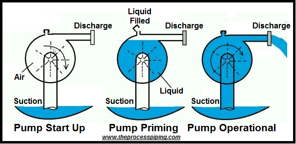
Priming a pump is probably the first and one of the most important thing one should do before operating it. Not priming a pump or not doing it properly makes majority of pump problems. Any problem in pump due to lack of priming may cause financial impact due to pump maintenance and the downtime of piping system due to a malfunctioning pump.
Requirement of priming pump
Priming reduces the risk of pump damage during start-up as it prevents the pump impeller to becomes gas-bound and thus incapable of pumping the desired liquid.
For reliable operation, pumps must first be primed; that is, air or gases to be expelled from the suction and impeller eye area and replaced with liquid to be pumped. The pump would not function properly when not completely filled with liquid. Along with compromised performance, not priming the pump and allowed to run without fluid, it will overheat the pump system and there will be a danger of damage to critical internal pump components.
Priming – Centrifugal Pump vs Positive Displacement Pump
In principle, all Positive Displacement Pumps are self-priming. In particular, this includes different type of rotary and reciprocating pumps. The priming of Positive Displacement Pump is required only at the time of first starting as under dry running conditions the pump may overheat. But in a Centrifugal Pump (except Self Priming Pump) priming is required in starting after every shutdown.
Centrifugal Pumps are designed to pump liquids not gases. Centrifugal Pump cannot suck the liquid, but it pushes the liquid from suction to discharge. Due to pressure difference created by the liquid pushed to the discharge with an additional push on liquid from the atmospheric pressure in the storage tank connected to pump suction piping, more liquid enter in the suction side of pump provided suction line is completely filled with liquid (primed). It’s sort of that pushes the liquid out and pulling effect is not so prominent. During the start-up of the pump if any air pocket is present at the suction side, then pump will push the air. As a result, air present in the suction side will try to expand and it will block the liquid from entering into the centrifugal pump.
Also explained in other words, in Centrifugal Pump the head developed (in meters of liquid that is pumped) depends on the velocities determined by diameter of the impeller and the impeller speed (rpm.). As the pressure developed is related to the head by the equation head = pr / sp. Weight, the pressure available will be proportional to the specific weight of the liquid. This means that the pressure (or pressure difference) created with air will be only around 1/800 times that with water (density of water = 1000 kg/ m3 and dry air at S.T.P has a density of 1.2 kg/m3). Therefore, if the pump is not primed, the suction pressure created will not be sufficient to lift water.
Whereas in Positive Displacement Pump during suction phase, piston moves backward and form a low pressure zone in the pump. This pressure difference between suction & storage tank is large enough to pull the liquid, even if air pocket is present in the suction line. In short, it creates a high initial vacuum during the start of suction stroke. Positive displacement pumps can evacuate all the air in its cylinder by virtue of its motion and therefore a better pressure (vacuum) is also generated. So, we need not have priming operation in positive displacement pumps.
Also, a common feature of all Positive Displacement Pumps is the use of close tolerance parts to prevent fluid returning from the discharge to the suction side. Depending on the effectiveness of these seals created by these close-tolerance parts, a positive displacement pump is capable of venting air from its suction to discharge and prevent the vented air from returning back. Whereas in Centrifugal Pumps, the pumping action is generated by the transfer of rotational energy from the impeller to the liquid. There are no seals between the suction and discharge sides of the pump making it ineffective with gases.
With Positive Displacement Pumps, there is a danger of cavitation occurring at the point when liquid starts to enter the pump and there is a liquid/air mixture. Under these conditions, vapour bubbles form and expand on the suction side of the pump. Upon reaching the high pressure, discharge side of the pump, the bubbles collapse violently causing vibration and damage to the pumping elements. For these reasons, it is important to refer to the manufacturer standard and operating procedure before using a positive displacement pump in an application where it must self-prime and, of necessity, be run dry for any period.
However, with a few modifications to the basic design, a centrifugal pump can be made Self Priming.