Unit 9
Air Compressors
Content:
The usage of compressed air is not limited only to industries, but they are also used in manufacturing, welding, constructions, power plants, ships, automobile plants, painting shops, and for filling breathing apparatus too. Thus, there are so many types of air compressors used specifically for the above purposes
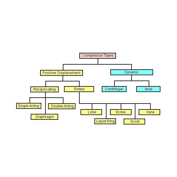
Types of Air Compressors:
Compressors are classified in many ways out of which the common one is the classification based on the principle of operation.
Types of Compressors:
1. Positive Displacement and
2. Roto-Dynamic Compressors.
Positive displacement compressors cab be further divided into Reciprocating and rotary compressors.
Under the classification of reciprocating compressors, we have
- In-line compressors,
- “V”-shaped compressors,
- Tandem Piston compressors.
- Single-acting compressors,
- Double-acting compressors,
- Diaphragm compressors.
The rotary compressors are divided into
- Screw compressors,
- Vane type compressors,
- Lobe and scroll compressors and other types.
Under the Roto-dynamic compressors, we have
- Centrifugal compressors, and the
- Axial flow compressors.
The compressors are also classified based on other aspects like
- Number of stages (single-stage, 2-stage and multi-stage),
- Cooling method and medium (Air cooled, water cooled and oil-cooled),
- Drive types ( Engine driven, Motor driven, Turbine driven, Belt, chain, gear or direct coupling drives),
- Lubrication method (Splash lubricated or forced lubrication or oil-free compressors).
- Service Pressure (Low, Medium, High)
Reciprocating compressor:
A reciprocating compressor is a positive-displacement machine that uses a piston to compress a gas and deliver it at high pressure.
This type of compressor uses piston-cylinder arrangement to compress the air. Whenever something moves back and forth it is considered as moving in reciprocating motion. Similarly, in this type piston moves back and forth inside the cylinder and compress the air. There are two sets of valves that take care of air intake and exhaust.
The compressor takes inside successive amount of volume of air from intake valve and confined it in closed surface at that time piston moves downward with the closure of intake valve. Then there is compression of air by reducing its volume .Now the piston moves upward and compress the air and then displace the compressed air through exhaust valve. And then again intake take place and cycle repeat itself
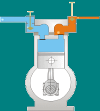
This type of compressor also called positive displacement machines. They are available in both as lubricated and oil-free.
The reciprocating compressor is single acting when the compressing is accomplished using only one side of piston and double acting when both the sides of piston used.
Major components of reciprocating compressor:
Reciprocating compressors are available in a variety of designs and arrangements. Major components in a typical reciprocating compressor are
- Frame
- Cylinders
- Distance Piece
- Piston
- Piston rings
- Cross Head
- Crankshaft
- Connecting Rod
- Valve
- Bearings
Some important parts are explained below:
Frame
The frame is a heavy, rugged housing containing all the rotating parts and on which the cylinder and crosshead guide is mounted. Compressor manufacturers rate frames for a maximum continuous horsepower and frame load .
Separable compressors are usually arranged in a balanced-opposed configuration characterized by an adjacent pair of crank throws that are 180 degrees out of phase and separated by only a crank web. The cranks are arranged so that the motion of each piston is balanced by the motion of an opposing piston.
Integral compressors typically have compressor and engine-power cylinders mounted on the same frame and are driven by the same crankshaft. Cylinders in integral compressors are usually arranged on only one side of the frame (i.e., not balanced-opposed).
Cylinder
The cylinder is a pressure vessel that contains the gas in the compression cycle. Single-acting cylinders compress gas in only one direction of piston travel. They can be either head end or crank end. Double-acting cylinders compress gas in both directions of piston travel .Most reciprocating compressors use double-acting cylinders.
Distance piece
The distance piece provides separation between the compressor cylinder and the compressor frame
Crankshaft
The crankshaft rotates around the frame axis and drives the connecting rod, piston rod, and piston.
Connecting rod connects the crankshaft to the crosshead pin
Crosshead converts the rotating motion of the connecting rod to a linear, oscillating motion that drives the piston
Piston rod connects the crosshead to the piston.
Piston and piston ring
The piston is located at the end of the piston rod and acts as the movable barrier in the compressor cylinder. Selection of material is based on strength, weight, and compatibility with the gas being compressed. The piston is usually made of a lightweight material such as aluminium or from cast iron or steel with a hollow centre for weight reduction. Thermoplastic wear (or rider) bands often are fitted to pistons to increase ring life and reduce the risk of piston-to-cylinder contact. Cast iron usually provides a satisfactorily low friction characteristic, eliminating the need for separate wear bands.
Wear bands distribute the weight of the piston along the bottom of the cylinder or liner wall. Piston rings minimize the leakage of gas between the piston and the cylinder or liner bore. Piston rings are made of a softer material than the cylinder or liner wall and are replaced at regular maintenance intervals. As the piston passes the lubricator feed hole in the cylinder wall, the piston ring gathers oil and distributes it over the length of the stroke.
Bearings
Bearings located throughout the compressor frame assure proper radial and axial positioning of compressor components. Main bearings are fitted in the frame to properly position the crankshaft. Crank pin bearings are located between the crankshaft and each connecting rod. Wrist pin bearings are located between each connecting rod and crosshead pin. Crosshead bearings are located at the top and bottom of each crosshead.
Most of the bearings in reciprocating compressors are hydrodynamic lubricated bearings. Pressurized oil is supplied to each bearing through oil supply grooves on the bearing surface. The grooves are sized to ensure adequate oil flow to prevent overheating.
Compressor valves
The essential function of compressor valves is to permit gas flow in the desired direction and to block all flow in the opposite (undesired) direction. Each operating end of a compressor cylinder must have two sets of valves. The set of inlet (suction) valves admits gas into the cylinder. The set of discharge valves is used to evacuate compressed gas from the cylinder. The compressor manufacturer normally specifies valve type and size.
Working of reciprocating compressor:
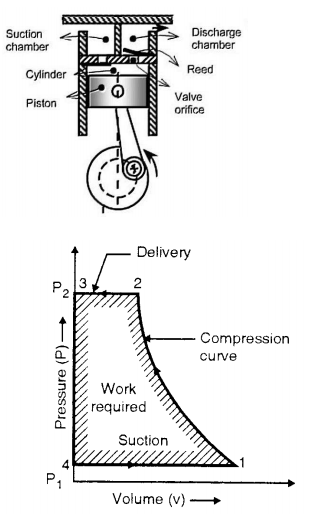
In single stage reciprocating air compressor, the entire compression is carried out in a single cylinder. The opening & closing of a simple check valve (plate or spring valve) depends upon the difference in pressure, if mechanically operated valves are used for suction & discharge then their functioning is controlled by cams. The weight of air in the cylinder will be zero when the piston is at top dead centre. At this position, you have to neglect clearance volume.
When piston starts moving downwards, the pressure inside the cylinder falls below atmospheric pressure& suction valve/inlet valve opens. The air is drawn into the cylinder through a suction filter element. This operation is known as suction stroke.
When the piston moves upwards, compresses the air in cylinder & inlet valve closes when the pressure reaches atmospheric pressure. Further compression follows as the piston moves towards the top of its stroke until when the pressure in the cylinder exceeds that in the receiver. This is compression stroke of a compressor. At the end of this stroke discharge/delivery valve opens & air is delivered to a receiver.
Advantages and disadvantages of reciprocating compressor
Advantages:
1. High thermal efficiency and low power consumption per unit
2. Convenient processing, low material requirements and low cost
3. Simple device system
4. Early design and production, mature manufacturing technology
5. Wide range of application
Disadvantages:
1. There are many moving parts, complex structure, heavy maintenance work and high maintenance cost
2. Speed Limited
3. The wear of piston ring, the wear of cylinder and the transmission mode of belt make the efficiency drop rapidly
4. Loud noise
5. The backward control system does not meet the needs of chain control and unattended, so although the price of piston machine is very low, it is often not accepted by users.
Applications:
The reciprocating compressor generally seen where there is requirement of high pressure and low flow(or discontinuous flow up to 30 bars).Mostly where the air is used for hand-tools, cleaning dust, small paint jobs, commercial uses, for examples-
1. In spray painting shop.
2. In workshop for cleaning machines.
3. For operation of pneumatic tool like rock drill, vibrator etc.
4. In automobile service station to clean vehicle.
5. To drive air motors in coal mines.
6. Food and beverage industry
Vane type compressors:
Vane Compressor is also known as Rotary Vane Compressor or Sliding Vane compressor. It was invented by Charles C. Barnes of Canada. He patented it on 16 June 1874. Vane Compressor is one of the most widely used products in today’s world. They serve a wide range of industries. It used centrifugal motion to generate compressed air. It is generally used for capacities up to 150 metre cube/min and for pressure ratio up to 8:5. They are very popular in automotive and hydraulic applications.
Construction:
Vane Compressor consists of a cylindrical rotor eccentrically placed in the casing. This casing has intake and delivery openings which are also known as inlet and outlet port. The inlet port of the casing is bigger as compared to the outlet port of the casing. Rotor has a drum in its centre.
This drum rotates eccentrically with respect to the casing. This rotor has several radial slots in it. Each radial slot has a vane fitted in it which is spring loaded.
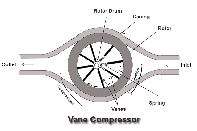
These vanes are made of steel or synthetic fibrous material. If the compressor is oil-lubricated, there will be a thin layer of oil in between the vane and housing.
The spaces between adjacent vanes form pockets of decreasing volume from a fixed inlet port to a fixed discharge port.
Larger the number of vanes smaller the leakage of air due to small pressure difference prevailing between the adjacent spaces around the rotor.
High pressure ratio requires large number of vanes ( 20 – 30 ). For a given pressure ratio, cane compressor requires less work input than that for roots blower.
Working:-
When the rotor rotates, vanes of the rotor move outward toward the casing due to centrifugal force experienced by them, until they touch the casing.
The rotor of the vane compressor rotates in the anti-clockwise direction.
When the vanes reaches the position where the distance between the rotor drum and casing is less the spring in the vanes compresses to maintain contact with the casing. As the spring compresses the space between the two adjacent vanes also decreases.
Similarly, when the vanes reach the position where the distance between the rotor drum and casing is more the spring in the vanes expands to maintain contact with the casing.
As the spring expands the space between the two adjacent vanes also increases.
When the vanes move downward the space between two adjacent vanes increases also space between rotor drum and casing increases which create vacuum. Thus, the gas is drawn in from the suction opening
near the inlet of the vane compressor, the space between two adjacent vanes increases due to increased distance between rotor drum and casing.
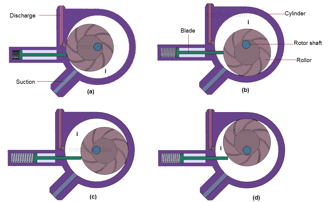
As the space increases between two adjacent vanes, vacuum is created near the inlet of vane compressor.
Due to the vacuum, the suction starts and the gas is drawn in from the inlet of the compressor. After that, as the rotor continues to rotate the compression of the entrapped gas starts due to a decrease in the space between adjacent vanes. As the space between vanes decreases, the volume of the gas decreases and the gas gets compressed.
After that, the high pressure gas which is compressed gets discharged from the outlet of the vane compressor. Nearly half of the rise of pressure of the gas is developed during the compression which is reversible compression. The remaining pressure rise occurs when the compressed gas is released from the outlet of the compressor.
Advantages of Vane Compressor:
1) It creates a good vacuum for suction.
2) Vane Compressor works well for continuous air supplied.
3) High pressure and high power compression are possible with vane compressor.
4) Vane compressors have a longer life expectancy.
5) They are ideally suited for moderate pressure using applications.
Disadvantages of Vane Compressor:
1) The vibration happens during the reciprocation of the cylinder.
2) Because of a greater number of moving parts maintenance cost is high.
Applications of Vane Compressor:
Vane Compressor has many applications. They serve a wide range of industries. Some of the applications of the vane compressor are:-
1) They are used in agriculture for operating farm equipment, material conveying, etc.
2) Used in the auto body paint shop for paint pump operation.
3) Used in tire and wheel shop for tire inflation.
4) Used in Dry Cleaning.
5) Used in the operation of air knives for cutting and peeling.
6) It is used in welding operations and air-operated metal and woodworking tools.
Rotary compressors are another type of famous compressors. It uses two Asymmetrical rotors that are also called helical screws to compress the air.
The rotors have a very special shape and they turn in opposite directions with very little clearance between them. The rotors are covered by cooling jackets. Two shafts on the rotors are placed that transfer their motion with the help of timing gears that are attached at the starting point of the shafts/compressor (as shown in the image).
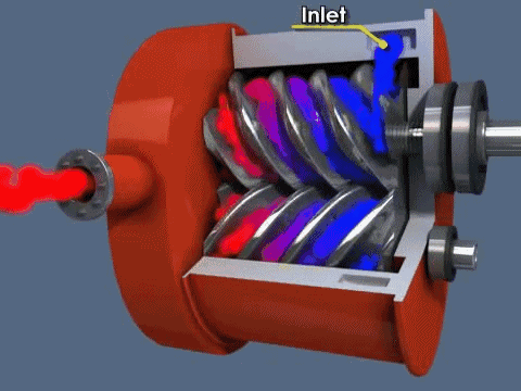
Working principle-Air sucked in at one end and gets trapped between the rotors and get pushed to other side of the rotors .The air is pushed by the rotors that are rotating in opposite direction and compression is done when it gets trapped in clearance between the two rotors. Then it pushed towards pressure side.
Rotary screw compressors are of two types oil-injected and oil-free.
Oil-injected is cheaper and most common than oil-free rotary screw compressors.
Advantages
- Less noisy.
- These are called the work-horses as they supply large amount of compress air.
- More energy efficient as compared to piston type compressors.
- The air supply is continuous as compared to reciprocating compressors.
- Relatively low end temperature of compressed air.
Disadvantages
- Expensive then piston-type compressors.
- More complex design.
- The maintenance is very important
- Minimum one day use is important in a weak to avoid rusting.
Rotary scroll compressor
They are one of the best compressor type in rotary compressors. The air is compressed using two spiral elements. One element is stationary and the other one moves in small eccentric circles inside the spiral. Air gets trapped inside the spiral way of that element and gets transported in small air-pockets to the centre of the spiral.
Simply air gets trapped at the outer edge and get compressed due to reduction of are as it travels from outer edge to inner edge . It takes about 2 to 3 turns for the air to reach the pressure output in the centre.
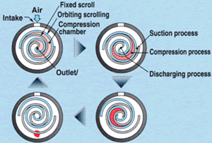
Advantages
- Very quiet.
- This is very compact in size.
- Simple design with not so many parts.
- Oil-free design and low maintenance.
Disadvantages
- Output capacity is low.
- Relatively expensive
- You have to buy a new scroll element with the failure of older one even if there is not any big problem.
- The temperature of compressed air is too much high.
Vane Type Rotary Compressor
This is another type of rotary compressor. There is a fixed casing in Vane type compressor in which a rotary rotor disc is placed which has slots that are used for holding the sliding plates.
Whenever rotor rotates the disc also rotates thus allowing the sliding plates to slide as the inner surface of casing is eccentric. Whenever the plate’s moves away from the centre a huge amount of air get trapped inside it and with the rotation the sliding plates converge due to its shape and the trapped air get compressed. This results in compression of air.
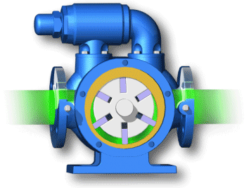 .
.
Advantages
- Easy maintenance.
- Simple in design.
Lobe Type Air Compressor
This is one of the simpler compressor type. In this there is no complicated moving part. There are two lobes attached to the driving shaft by the prime mover. These lobes are displaced with 90 degrees to one another. Thus, if one of the lobe is in horizontal direction the other lobes will be exactly positioned at 90 degree i.e. in vertical direction.
The air gets trapped from one end and as the lobes rotate the air gets compressed as shown in image. The compressed air is then delivered to delivery line.
A multi-stage compressor is one in which there are several cylinders of different diameters. The intake of air in the first stage gets compressed and then it is passed over a cooler to achieve a temperature very close to ambient air. This cooled air is passed to the intermediate stage where it is again getting compressed and heated. This air is again passed over a cooler to achieve a temperature as close to ambient as possible. Then this compressed air is passed to the final or the third stage of the air compressor where it is compressed to the required pressure and delivered to the air receiver after cooling sufficiently in an after-cooler.
Advantages of Multi-stage compression:
- The work done in compressing the air is reduced, thus power can be saved
- Prevents mechanical problems as the air temperature is controlled
- The suction and delivery valves remain in cleaner condition as the temperature and vaporization of lubricating oil is less
- The machine is smaller and better balanced
- Effects from moisture can be handled better, by draining at each stage
- Compression approaches near isothermal
- Compression ratio at each stage is lower when compared to a single-stage machine
- Light moving parts usually made of aluminium, thus less cost and better maintenance
Refer to the diagram of a multi-stage compressor, where it is evident that the work done by the compressor is less when compared to a single-stage machine for same delivery pressure.
We know that PVn = C, where n is the polytropic compression index.
If we want to compress air from atmospheric pressure to a pressure of 30 bar, and say the ambient temperature is 27 degree Celsius:
The compression index n = 1.35 and the compression ratio for single-stage compressor would be 30:1.
Also, we know that T1/T2 = (P1/P2) ((n-1)/n).
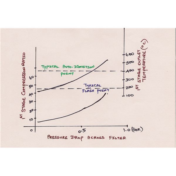
Thus, when calculated using the above expression, T2= 450 degree Celsius. Thus, it is evident that the delivery temperature of compressed air is 450 degree Celsius.