UNIT 2
Loci of Points
A machine is made of the various types of mechanisms for transmitting motions. These mechanisms consist of interrelated links moving on the required path. Dimensions (generally lengths) of the links of the mechanism can be determined by plotting the path of required points.
Loci of points:
A locus (plural loci) is the path of a point which moves in space.
(i) The locus of a point P moving in a plane about another point O in such a way
That its distance from it is constant, is a circle of radius equal to OP (fig. 1).
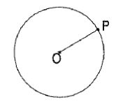
Figure 1
(ii) The locus of a point P moving in a plane in such a way that its distance from a fixed line AB is constant, is a line through P, parallel to the fixed line (fig. 2).
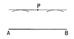
Figure 2
(iii) When the fixed line is an arc of a circle, the locus will A be another arc drawn through P with the same centre· (fig. 3).
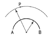
Figure 3
(iv) The locus of a point equidistant from two fixed points A and B in the same plane, is the perpendicular bisector of the line joining the two points (fig. 4).
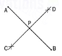
Figure 4
(v) The locus of a point equidistant from two fixed non-parallel straight lines AB and CD will be a straight line bisecting the angle between them (fig. 5).
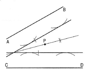
Figure 5
In simple mechanisms, it is often necessary to know the paths of points on their moving parts. These are determined by assuming a number of different positions of the moving parts and then locating the corresponding positions of the points.
The slider crank mechanism shown diagrammatically in fig. 6 is one of the
Simplest mechanisms and it is used in internal combustion engine, sewing machine and printing press etc. The end A of the connecting rod AB is connected to the crank OA which rotates about 0. The other end B is attached to a slider which slides along a straight line. The locus of A will be a circle and that of the end B will be a straight line. The locus of any other point, say P, on the connecting rod will be neither a circle nor a straight line and may be determined:
(i) by assuming various positions of the crank-end A,
(ii) by obtaining the corresponding positions of the end B and finally
(iii) by locating the positions of P on the lines joining the first two positions.
A smooth curve drawn through the points thus located will be the locus of P.
Such curves are known as coupler curves.
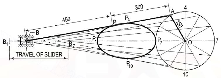
Figure 6
This mechanism consists of four links. It is widely used in locomotive, steering mechanism of the car, pantograph and straight-line mechanisms.
1. Two equal cranks AB and CD connected by the link BD, rotate in opposite directions. Draw the focus of a point P on BO and of Q along extension of the rod beyond B for one revolution of AB.
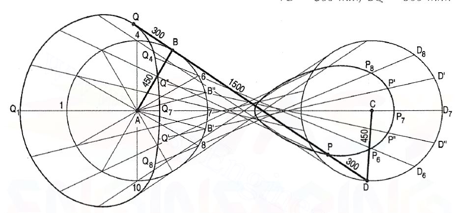
AB = CO = 450 mm; AC = BO = 15OO mm;
PO = 300 mm; BQ 300 mm.
(i) Divide one of the circles (say path of B), into 12 equal parts.
(ii) Determine the position of O on its path (the other circle), for every position of B and find the corresponding positions of P and Q for these positions as shown. It will be found that there is a wide gap between the points for positions 6, 7 and 8 of the end B. A few more positions such as AB' and AB" etc. may be taken and points P', P", Q', Q" etc. may be located.