UNIT 7
Orthographic Projections
If straight lines are drawn from various points on the contour of an object to meet a plane, the object is said to be projected on that plane. The figure formed by joining, in correct sequence, the points at which these lines meet the plane, is called the projection of the object. The lines from the object to the plane are called projectors.
Methods of Projection:
Following four methods of projection are commonly used,
1) Orthographic projection.
2) Isometric projection.
3) Oblique projection.
4) Perspective projection.
In the above methods 2, 3 and 4 represent the object by a pictorial view as eyes see it. In these methods of projection, a three-dimensional object is represented on a projection plane by one view only, while in the orthographic projection an object is represented by two or three views on the mutual perpendicular projection planes. Each projection view represents two dimensions of an object. For the complete description of the three-dimensional object at least two or three views are required.
Most products are made from multiview drawings that allow you to view an object with the line of sight perpendicular to the surface you are looking at. The one major shortcoming of this form of drawing is the lack of depth. A single view of the
Object providing a more realistic representation is often helpful for visual relation. This realistic single view is achieved with pictorial drawing.
The most common forms of pictorial drawing used in engineering drawing are isometric and oblique. These two basic forms of pictorial drawing are easy to create if you can visualize objects in orthographic projection and three dimensions. Isometric drawing belongs to a family of pictorial representation
Known as axonometric projection. Two other similar forms of drawing are in this group. Dimetric projection involves the use of two different scales. The simplest is isometric, which uses a single scale for all axes. Trimetric projection is the most involved of the three and uses three different scales for measurement. Figure 1 illustrates the differences in scale between isometric, diametric, and trimetric drawings.

Figure 1
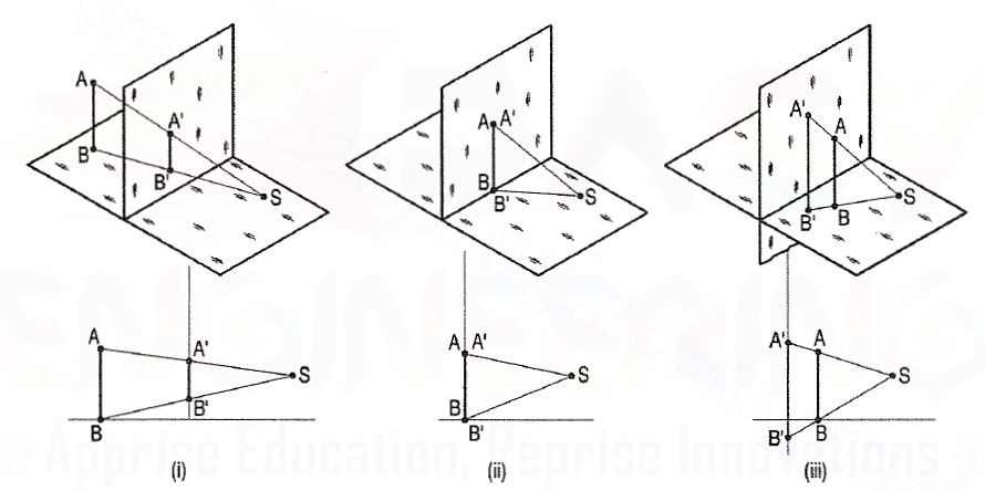
The position of the picture plane relative to the object, determines the size of the
Perspective view. The perspective will show the object reduced in size when it is
Placed behind the picture plane. If the object is moved nearer the picture plane,
The size of the perspective will increase. When the picture plane coincides with the object, the perspective of the object will be of its exact size. When the object is placed in front of the picture plane, its perspective, when projected back, will show the object enlarged in size.
In fig. 1(i), the line AB is behind the picture plane. Its perspective A'B' is
Shorter than AB. In fig. 1(ii), AB is in the picture plane; its perspective A'B' is
Equal to AB and coincides with it. Fig. 1(iii) shows the line AB placed in front
Of the picture plane; when projected back on the picture plane, its perspective A 'B' is longer than AB.

Figure 2
We have assumed the object to be situated in front of the V.P. And above the H.P. i.e. in the first quadrant and then projected it on these planes. This method of projection is known as first-angle projection method. The object lies between the observer and the plane of projection. In this method, when the views are drawn in their relative positions, the top view comes below the front view. In other words, the view seen from above is placed on the other side of (i.e. below) the front view. Each projection shows the view of that surface (of the object) which is remote from the plane on which it is projected, and which is nearest to the observer.
Third angle projection:
In this method of projection, the object is assumed to be situated in the third quadrant [fig. 11(a)]. The planes of projection are assumed to be transparent. They lie between the object and the observer. When the observer views the object from the front, the rays of sight intersect the V.P. The figure formed by joining the points of intersection in correct sequence is the front view of the object. The top view is obtained in a similar manner by looking from above. When the two planes are brought in line with each other, the views will be shown in fig.11 (b). The top view in this case comes above the front view.

Symbols for methods of projection:
For every drawing it is essential to indicate the method of projection adopted. This is done by means of a symbolic figure drawn within the title block on the drawing sheet. These symbolic figures are the projections of a frustum of cone of convenient dimensions according to the size of drawing.

Problems:
1) A L-shaped solid object having dimensions of length (L), width (W) and height (H). If this object is lying in the first quadrant. Draw its front view, top view and side view.
Steps:
(i) Mark the visible corners of the given block as shown front view: Assume that you are viewing the object in the direction of the arrow towards the imaginary V.P. What you will see is a rectangle of height (H) and width (W) on V.P. This will be the front view. To draw this view:
(ii) Draw a reference line xy, which represents the intersecting line of the planes V.P. And H.P. Draw a rectangle as shown W and H, above xy make sure that the width is parallel to the Iinexy. The rectangle is the front orthogonal view of the object.
(iii) Draw a line parallel to and thickness of h to the line 1-2. The rectangle 1-2-4-3 is the front view of the horizontal L-shaped stem of the object.

FULL SECTIONS
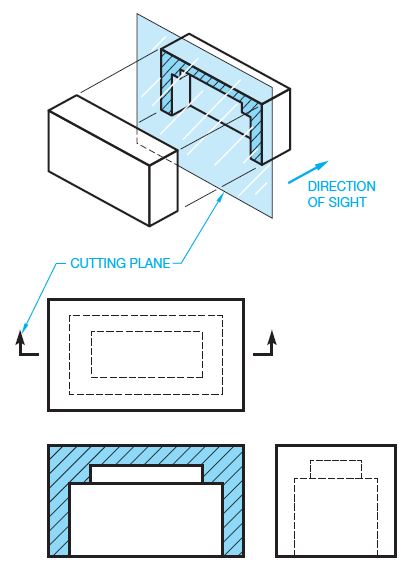
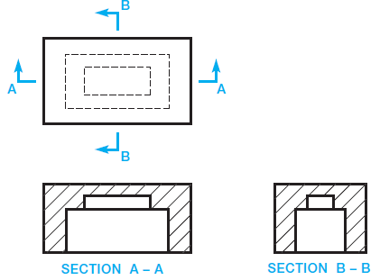
A full section is drawn when the cutting plane extends completely through the object, usually along a center plane as shown in Figure 3. The object shown in Figure 3 could have used two full sections to further clarify hidden features. In such a case, the cutting planes and related views are labelled (see Figure 4). The cutting-plane line can be omitted when the relationship between views is obvious. Confirm this practice with your instructor or employer. It is normally best to show the cutting-plane line for clarity.

Figure 3

Figure 4