UNIT 4
Projections of Points and Lines
First angle projection:
We have assumed the object to be situated in front of the V.P. And above the H.P. i.e. in the first quadrant and then projected it on these planes. This method of projection is known as first-angle projection method. The object lies between the observer and the plane of projection. In this method, when the views are drawn in their relative positions, the top view comes below the front view. In other words, the view seen from above is placed on the other side of (i.e. below) the front view. Each projection shows the view of that surface (of the object) which is remote from the plane on which it is projected, and which is nearest to the observer.
Third angle projection:
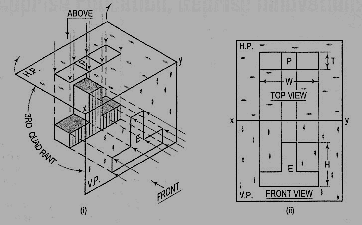
In this method of projection, the object is assumed to be situated in the third quadrant [fig. (a)]. The planes of projection are assumed to be transparent. They lie between the object and the observer. When the observer views the object from the front, the rays of sight intersect the V.P. The figure formed by joining the points of intersection in correct sequence is the front view of the object. The top view is obtained in a similar manner by looking from above. When the two planes are brought in line with each other, the views will be shown in fig. (b). The top view in this case comes above the front view.
.
A point may be situated, in space, in any one of the four quadrants formed by the two principal planes of projection or may lie in any one or both. Its projections are obtained by extending projectors perpendicular to the planes.
One of the planes is then rotated so that the first and third quadrants are opened out. The projections are shown on a flat surface in their respective positions either above or below or in xy.
If a point is situated in the first quadrant,
The pictorial view [fig. (i)] shows a point A situated above the H.P. And in front of the V.P., i.e. in the first quadrant. a' is its front view and the top view. After rotation of the plane, these projections will be shown in fig. (ii).
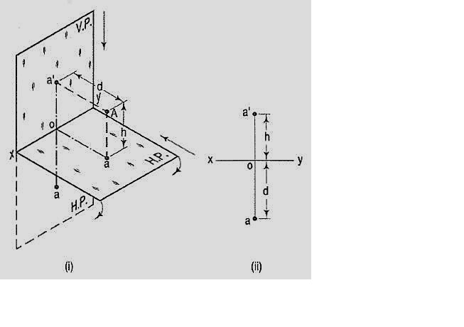
The front view a' is above xy and the top view a below it. The line joining a' and a (which also is called a projector), intersects xy at right angles at a point o. It is quite evident from the pictorial view that a'o = Aa, i.e. the distance of the front view from xy = the distance of A from the H.P. Viz. h. Similarly, ao = Aa',i.e. the distance of the top view from xy = the distance of A from the V.P. Viz. d.
If a point is situated in second quadrant,
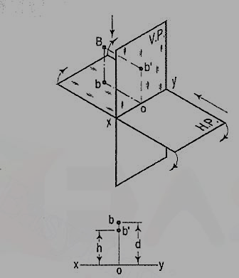
A point B (fig.) is above the H.P. And behind the V.P., i.e. in the second quadrant. b' is the front view and b the top view. When the planes are rotated, both the views are seen above xy. Note that b'o = Bb and bo = Bb'.
If a point is situated in third quadrant,
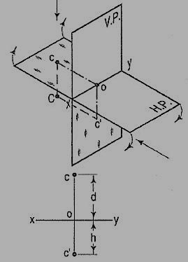
A point C (fig.) is below the H.P. And behind the Y.P., i.e. in the third quadrant. Its front view c' is below xy and the top view c above xy. Also, c'o = Cc and co = Cc'.
If a point is situated in 4th quadrant,
A point f (fig. 17) is below the H.P. And in front of the V.P., i.e. in the fourth quadrant. Both its projections are below xy, and e'o = Ee and eo = Ee'.
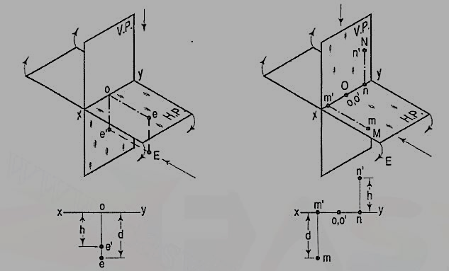
General conclusions:
1. The fine joining the top view and the front view of a point is always perpendicular to xy. It is called a projector.
2. When a point is above the H.P., its front view is above xy; when it is below the H.P., the front view is below xy. The distance of a point from the H.P. Is shown by the length of the projector from its front view to xy.
3. When a point is in front of the V.P., its top view is below xy; when it is behind the V.P., the top view is above xy. The distance of a point from the V.P. Is shown by the length of the projector from its top view to xy.
4. When a point is in a reference plane, its projection on the other reference plane is in xy.
Examples:
1. A point P is in the first quadrant. Its shortest distance from the intersection point of H.P., V.P. And Auxiliary vertical plane, perpendicular to the H.P. And V.P. Is 70 mm and it is equidistant from principal planes (H.P. And V.P.). Draw the projections of the point and determine its distance from the H.P. And V.P.
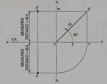
Note: ‘O’ represents intersection of H.P., V.P. And A.V.P.
Drawing steps:
1. Draw xy and x1 y1 perpendicular reference lines.
2. ‘O’ represents intersection of H.P., V.P. And A.V.P.
3. Draw from O a line inclined at 45° of 70 mm length.
4. Project from P" on xy line and x1 y1. The projections are n and m respectively as shown in figure. From O draw arc intersecting x1 y1.
5. Draw a parallel line at convenient distance from x1 y1. Extend P"m to intersect
a parallel line at p' and p as shown.
6. Measure distance from xy line, which is nearly 49.4974 mm say 49.5 mm.
A straight line is the shortest distance between two points. Hence, the projections of a straight line may be drawn by joining the respective projections of its ends which are points.
The position of a straight line may also be described with respect to the two reference planes. It may be:
1. Parallel to one or both the planes.
2. Contained by one or both the planes.
3. Perpendicular to one of the planes.
4. Inclined to one plane and parallel to the other.
5. Inclined to both the planes.
6. Projections of lines inclined to both the planes.
7. Line contained by a plane perpendicular to both the reference planes.
8. True length of a straight line and its inclinations with the reference planes.
9. Traces of a line.
10. Methods of determining traces of a line.
11. Traces of a line, the projections of which are perpendicular to xy.
12. Positions of traces of a line.
Line parallel to one or both the planes:
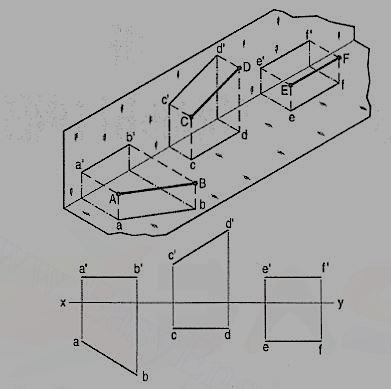
(a) Line AB is parallel to the H.P.
a and b are the top views of the ends A and B respectively. It can be clearly seen that the figure ABba is a rectangle. Hence, the top view ab is equal to AB.
a'b' is the front view of AB and is parallel to xy.
(b) Line CD is parallel to the V.P. The line c'd' is the front view and is equal to CD; the top view cd is parallel to xy.
(c) Line ff is parallel to the H.P. And the V.P. Ef is the top view and e'f' is the front view; both are equal to ff and parallel to xy.
Hence, when a line is parallel to a plane, its projection on that plane is equal to its true length; while its projection on the other plane is parallel to the reference line.
Line contained by one or both the planes:
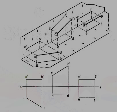
Line AB is in the H.P. Its top view ab is equal to AB; its front view a' b' is in xy.
Line CD is in the V.P. Its front view c'd' is equal to CO; its top view cd is in xy.
Line ff is in both the planes. Its front view e' f' and the top view ef coincide with each other in xy.
Hence, when a line is contained by a plane, its projection on that plane is equal to its true length; while its projection on the other plane is in the reference line.
Line perpendicular to one of the planes:
When a line is perpendicular to one reference plane, it will be parallel to the other.
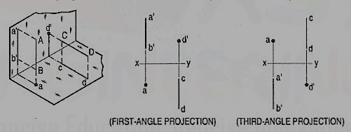
(a) Line AB is perpendicular to the H.P. The top views of its ends coincide in the point a. Hence, the top view of the line AB is the point a. Its front view a' b' is equal to AB and perpendicular to xy.
(b) Line CD is perpendicular to the V.P. The point d' is its front view and the line cd is the top view. Cd is equal to CD and perpendicular to xy.
Hence, when a line is perpendicular to a plane its projection on that plane is a point; while its projection on the other plane is a line equal to its true length and perpendicular to the reference line.
In first-angle projection method, when top views of two or more points coincide, the point which is comparatively farther away from xy in the front view will be visible; and when their front views coincide, that which is farther away from xy in the top view will be visible.
In third-angle projection method, it is just the reverse. When top views of two or more points coincide the point, which is comparatively nearer xy in the front view will be visible; and when their front views coincide, the point which is nearer xy in the top view will be visible.
Line inclined to one plane and parallel to the other:
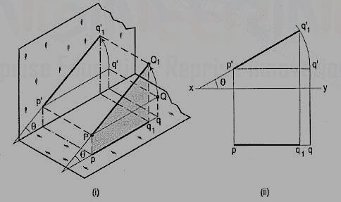
The inclination of a line to a plane is the angle which the line makes with its projection on that plane.
Line PQ1 [fig. 22 (i)] is inclined at an angle 8 to the H.P. And is parallelto the V.P. The inclination is shown by the angle 8 which PQ1 makes withits own projection on the H.P., viz. The top view pq1.
The projections [fig. 22 (ii)] may be drawn by first assuming the line to be parallel to both the H.P. And the V.P. Its front view p'q' and the top view pq will both be parallel to xy and equal to the true length. When the line is turned about the end P to the position PQ1 so that it makes the angle 8 with the H.P. While remaining parallel to the V.P., in the front view the point q' will move along an arc drawn with p' as center and p'q' as radius to a point q'1 so that p'q'1 makes the angle 8 with xy. In the top view, q will move towards p along pq to a point q1 on the projector through q'1. p'q'1 and pq1 are the front view and the top view respectively of the line PQ1.
Line inclined to both the planes:
A line AB (fig. 23) is inclined at θ to the H.P. And is parallel to the V.P.The end A is in the H.P. AB is shown as the hypotenuse of a right-angledtriangle, making the angle θ with the base.
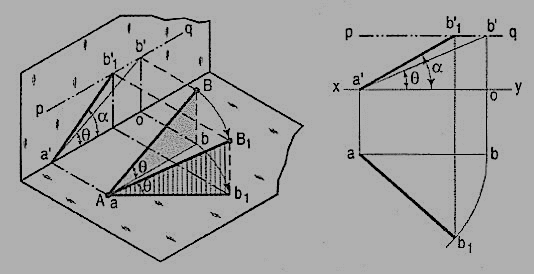
The top view ab is shorter than AB and parallel to xy. The front view a'b' is equal to AB and makes the angle θ with xy.
Keeping the end, A fixed and the angle θ with the H.P. Constant, if the end B is moved to any position, say B1, the line becomes inclined to the V.P. Also.
In the top view, b will move along an arc, drawn with a as center and ab as radius, to a position b1. The new top view ab1 is equal to ab but shorter than AB.
In the front view, b' will move to a point b'1 keeping its distance from xy constant and equal to b'o; i.e. it will move along the line pq, drawn through b' and parallel to xy. This line pq is the locus or path of the end B in the front view. b'1 will lie on the projector through b1. The new front view a'b'1 is shorter than a'b' (i.e. AB) and makes an angle a with xy. a is greater than θ.
Thus, if the inclination θ of AB with the H.P.is constant, even when it is inclined to the V.P.
(i) its length in the top view, viz. Ab remains constant; and
(ii) the distance between the paths of its ends in the front view,viz. b'o remains constant.
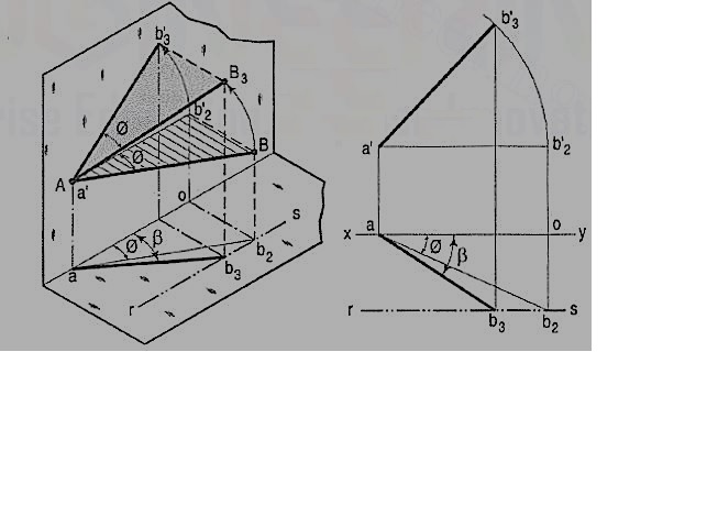
b) The same line AB (fig. 24) is inclined at ϕ to the V.P. And is parallel to the H.P. Its end A is in the V.P. AB is shown as the hypotenuse of a right-angled triangle making the angle ϕ with the base.
The front view a'b'2 is shorter than AB and parallel to xy. The top view ab2 is equal to AB and makes an angle ϕ with xy.
Keeping the end, A fixed and the angle ϕ with the V.P. Constant, if B is moved to any position, say B3, the line will become inclined to the H.P. Also.
In the front view, b'2, will move along the arc, drawn with a' as center and a'b'2 as radius, to a position b'3. The new front view a'b'3 is equal to a'b'2 but is shorter than AB.
In the top view, b2 will move to a point b3 along the line rs, drawn through b2 and parallel to xy, thus keeping its distance from the path of a, viz. b2o constant. Rs is the locus or path of the end B in the top view. The point b3 lies on the projector through b'3. The new top view ab3 is shorter than ab2 (i.e. AB) and makes an angle β with xy. β is greater than ϕ.
Here also we find that, if the inclination of AB with the V.P. Does not change, even when it becomes inclined to the H.P.
(i) its length in the front view, viz. a'b'2 remains constant; and
(ii) the distance between the paths of its ends in the top view, viz. b2o remains constant.
Hence, when a line is inclined to both the planes, its projections are shorter than the twe length and inclined to xy at angles greater than the true inclinations. These angles viz. α and β are called apparent angles of inclination.
Traces of a line:
When a line is inclined to a plane, it will meet that plane, produced if necessary. The point in which the line or line-produced meets the plane is called its trace.
The point of intersection of the line with the H.P. Is called the horizontal trace, usually denoted as H.T. And that with the V.P. Is called the vertical trace or V.T.
Refer to fig. 25.
(i) A line AB is parallel to the H.P. And the V.P. It has no trace.
(ii) A line CD is inclined to the H.P. And parallel to the V.P. It has only the H.T. But no V.T.
(iii) A line ff is inclined to the V.P. And parallel to the H.P. It has only the V.T. But no H.T.
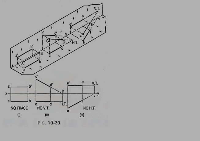
Thus, when a line is parallel to a plane it has no trace upon that plane.
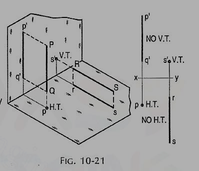
(i) A line PQ is perpendicular to the H.P. Its H.T. Coincides with its top view which is a point. It has no V.T.
(ii) A line RS is perpendicular to the V.P. Its V.T. Coincides with its front view which is a point. It has no H.T.
Hence, when a line is perpendicular to a plane, its trace on that plane coincides with its projection on that plane. It has no trace on the other plane.
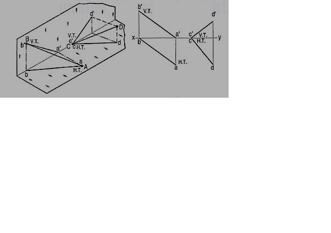
Figure 27
(i) A line AB has its end A in the H.P. And the end B in the V.P. Its H.T. Coincides with the top view of A and the V.T. Coincides with b' the front view of B.
(ii) A line CD has its end C in both the H.P. And the V.P. Its H.T. And V.T. Coincide with c and c' (the projections of C) in xy. Hence, when a line has an end in a plane, its trace upon that plane coincides with the projection of that end on that plane.
Methods of determining traces of a line:
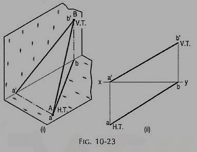
Method I:
Fig. 28 (i) shows a line AB inclined to both the reference planes. Its end A is in the H.P. And 8 is in the V.P. a'b' and ab are the front view and the top view respectively [fig. 28 (ii)].
The H.T. Of the line is on the projector through a' and coincides with a. The V.T. Is on the projector through b and coincides with b'.
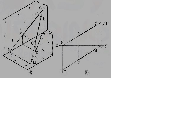
Let us now assume that AB is shortened from both its ends, its inclination with the planes remaining constant. The H.T. And V.T. Of the new line CD are still the same as can be seen clearly in fig. 29 (i). c'd' and cd are the projections of CD [fig. 29 (ii)]. Its traces may be determined as described below.
(i) Produce the front view c'd' to meet xy at a point h.
(ii) Through h, draw a projector to meet the top view cd-produced, at the H.T. Of the line.
(iii) Similarly, produce the top view cd to meet xy at a point v.
(iv) Through v, draw a projector to meet the front view c'd'-produced, at the V.T. Of the line.
Method II: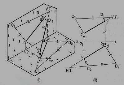
c'd' and cd are the projections of the line CD [fig. 30 (ii)]. Determine the true length C1D1 from the front view c'd' by trapezoid method. The point of intersection between c'd'-produced and C1D1-produced is the V.T. Of the line.
Similarly, determine the true length C2D2 from the top view ed. Produce them to intersect at the H.T. Of the line.
Examples:
1. A line AB 50 mm long, has its end A in both the H.P. And the V.P. It is inclined at 30° to the H.P. And at 45° to the V.P. Draw its projections.
As the end A is in both the planes, its top view and the front view will coincide in xy.
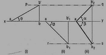
(i) Assuming AB to be parallel to the V.P. And inclined at θ (equal to 30°) to the H.P., draw its front view ab' (equal to AB) and project the top view ab.
(ii) Again, assuming AB to be parallel to the H.P. And inclined at ϕ (equal to 45°) to the V.P., draw its top view ab1 (equal to AB). Project the front view ab'1.
Ab and ab'1 are the lengths of AB in the top view and the front view respectively, and pq and rs are the loci of the end B in the front view and the top view respectively.
(iii) With a as center and radius equal to ab'1, draw an arc cutting pq in b'2. With the same center and radius equal to ab, draw an arc cutting rs in b2.
Draw lines joining a with b'2 and b2. Ab'2 and ab2 are the required projections.
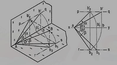
Fig. Shows in pictorial and orthographic views, the solution obtained with all the above steps combined in one figure only.
Plane figures or surfaces have only two dimensions, viz. Length and breadth. They do not have thickness. A plane figure may be assumed to be contained by a plane, and its projections can be drawn, if the position of that plane with respect to the principal planes of projection is known.
In this chapter, we shall discuss the following topics:
1. Types of planes and their projections.
2. Traces of planes.
Type of planes:
Planes may be divided into two main types:
(1) Perpendicular planes.
(2) Oblique planes.
Perpendicular planes:
These planes can be divided into the following sub-types:
(i) Perpendicular to both the reference planes.
(ii) Perpendicular to one plane and parallel to the other.
(iii) Perpendicular to one plane and inclined to the other.
Perpendicular to both the reference planes (fig 1):
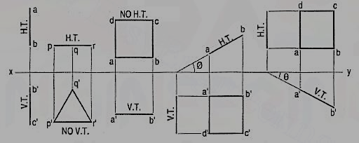
A square ABCD is perpendicular to both the planes. Its H.T. And V.T. Are in a straight-line perpendicular to xy.
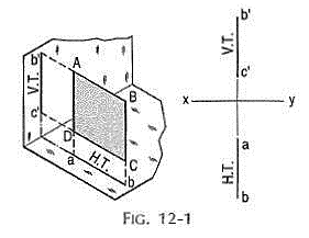
The front view b'c' and the top view ab of the square are both lines coinciding with the V.T. And the H.T. Respectively.
Perpendicular to one plane and parallel to the other plane:
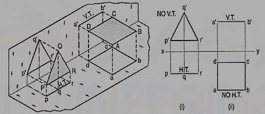
a) Plane, perpendicular to the H.P. And parallel to the V.P. [fig. 2(i)]. A triangle PQR is perpendicular to the H.P. And is parallel to the V.P. Its H.T. Is parallel to xy. It has no V.T.
The front view p'q'r' shows the exact shape and size of the triangle. The top view pqr is a line parallel to xy. It coincides with the H.T.
(b) Plane, perpendicular to the V.P. And parallel to the H.P. [fig. 2(ii)]. A square ABCD is perpendicular to the V.P. And parallel to the H.P. Its V.T. Is parallel to xy. It has no H.T.
The top view abed shows the true shape and true size of the square. The front view a'b' is a line, parallel to xy. It coincides with the V.T.
Perpendicular to one plane and inclined to the other plane:
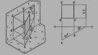
A square ABCD is perpendicular to the H.P. And inclined at an angle φ to the V.P. Its V.T. Is perpendicular to xy. Its H.T. Is inclined at φ to xy.
Its top view ab is a line inclined at φ to xy. The front view a'b'c'd' is smaller than ABCD.
(b) Plane, perpendicular to the V.P. And inclined to the H.P. (fig. 4).
A square ABCD is perpendicular to the V.P. And inclined at an angle θ to the H.P. Its H.T. Is perpendicular to xy. Its V.T. Makes the angle e with xy. Its front view a'b' is a line inclined at θ to xy. The top view abed is a rectangle which is smaller than the square ABCD.
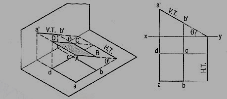
Fig. 5 shows the projections and the traces of all these perpendicular planes by third-angle projection method.
Oblique planes:
Planes which are inclined to both the reference planes are called oblique planes.
Traces of planes:
A plane, extended if necessary, will meet the reference planes in lines, unless it is parallel to any one of them.
These lines are called the traces of the plane. The line in which the plane meets the H.P. Is called the horizontal trace or the H.T. Of the plane. The line in which it meets the V.P. Is called its vertical trace or the V.T. A plane is usually represented by its traces.
General conclusions:
(1) Traces:
(a) When a plane is perpendicular to both the reference planes, its traces lie on a straight-line perpendicular to xy.
(b) When a plane is perpendicular to one of the reference planes, its trace upon the other plane is perpendicular to xy (except when it is parallel to the other plane).
(c) When a plane is parallel to a reference plane, it has no trace on that plane. Its trace on the other reference plane, to which it is perpendicular, is parallel to xy.
(d) When a plane is inclined to the H.P. And perpendicular to the V.P., its inclination is shown by the angle which its V.T. Makes with xy. When it is inclined to the V.P. And perpendicular to the H.P., its inclination is shown by the angle which its H.T. Makes with xy.
(e) When a plane has two traces, they, produced if necessary, intersect in xy (except when both are parallel to xy as in case of some oblique planes).
(2) Projections:
(a) When a plane is perpendicular to a reference plane, its projection on that plane is a straight line.
(b) When a plane is parallel to a reference plane, its projection on that plane shows its true shape and size.
(c) When a plane is perpendicular to one of the reference planes and inclined to the other, its inclination is shown by the angle which its projection on the plane to which it is perpendicular, makes with xy. Its projection on the plane to which it is inclined, is smaller than the plane itself.
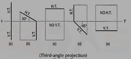
Problem 1. Show by means of traces, each of the following planes:
(a) Perpendicular to the H.P. And the V.P.
(b) Perpendicular to the H.P. And inclined at 30° to the V.P.
(c) Parallel to and 40 mm away from the V.P.
(d) Inclined at 45° to the H.P. And perpendicular to the V.P.
(e) Parallel to the H.P. And 25 mm away from it.
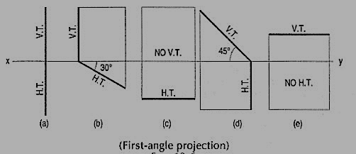
(a) The H.T. And the V.T. Are in a line perpendicular to xy.
(b) The H.T. Is inclined at 30° to xy; the V.T. Is normal to xy; both the traces intersect in xy.
(c) The H.T. Is parallel to and 40 mm away from xy. It has no V.T.
(d) The H.T. Is perpendicular to xy; the V.T. Makes 45° angle with xy; both intersect in xy.
(e) The V.T. Is parallel to and 25 mm away from xy. It has no H.T.
Projection of planes parallel to one of the reference planes:
The projection of a plane on the reference plane parallel to it will show its true shape. Hence, beginning should be made by drawing that view. The other view which will be a line, should then be projected from it.
Note: When the plane is parallel to the H.P.: The top view should be drawn first, and the front view projected from it.
Problem:
An equilateral triangle of 50 mm side has its V.T. Parallel to and 25 rnm above xy. It has no H.T. Draw its projections when one of its sides is inclined at 45° to the V.P.
As the V.T. Is parallel to xy and as there is no H.T. The triangle is parallel to the H.P. Therefore, begin with the top view.
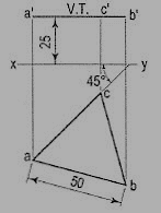
(i) Draw an equilateral triangle abc of 50 mm side, keeping one side, say ac, inclined at 45° to xy.
(ii) Project the front view, parallel to and 25 mm above xy, as shown in fig. 7.
When the plane is parallel to V.P.
Beginning should be made with the front view and the top view projected from it.
Problem:
A square ABCD of 40 mm side has a corner on the H.P. And 20 mm in front of the V.P. All the sides of the square are equally inclined to the H.P. And parallel to the V.P. Draw its projections and show its traces.
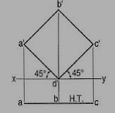
As all the sides are parallel to the V.P., the surface of the square also is parallel to it. The front view will show the true shape and position of the square.
(i) Draw a square a'b'c'd' in the front view with one corner in xy and all its sides inclined at 45° to xy.
(ii) Project the top view keeping the line ac parallel to xy and 30 mm below it. The top view is its H.T. It has no V.T.
Projections of planes inclined to one reference plane and perpendicular to other:
When a plane is inclined to a reference plane, its projections may be obtained in two stages. In the initial stage, the plane is assumed to be parallel to that reference plane to which it must be made inclined. It is then tilted to the required inclination in the second stage.
1) Plane, Inclined to the H.P. And perpendicular to the V.P.:
When the plane is inclined to the H.P. And perpendicular to the V.P., in the initial stage, it is assumed to be parallel to the H.P. Its top view will show the true shape. The front view will be a line parallel to xy. The plane is then tilted so that it is inclined to the H.P. The new front view will be inclined to xy at the true inclination. In the top view the corners will move along their respective paths (parallel to xy).
Problem:
A regular pentagon of 25 mm side has one side on the ground. Its plane is inclined at 45° to the H.P and perpendicular to the V.P. Draw its projections and show its traces.
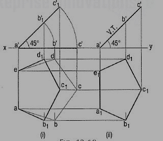
Assuming it to be parallel to the H.P.
(i) Draw the pentagon in the top view with one side perpendicular to xy [fig. 9 (i)]. Project the front view. It will be the line a'c' contained by xy.
(ii) Tilt the front view about the point a', so that it makes 45° angle with xy.
(iii) Project the new top view ab1c1d1e upwards from this front view and horizontally from the first top view. It will be more convenient if the front view is reproduced in the new position separately and the top view projected from it, as shown in fig. 9 (ii). The V.T. Coincides with the front view and the H.T. Is perpendicular to xy, through the point of intersection between xy and the front view-produced.
2) Plane, inclined to the V.P. And perpendicular to the H.P.:
In the initial stage, the plane may be assumed to be parallel to the V.P. And then tilted to the required position in the next stage.
Problem:
Draw the projections of a circle of 50 mm diameter, having its plane vertical and inclined at 30° to the V.P. Its center is 30 mm above the H.P. And 20 mm in front of the V.P. Show also its traces.
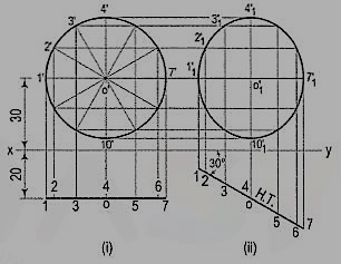
A circle has no corners to project one view from another. However, many points, say twelve, equal distances apart, may be marked on its circumference.
(i) Assuming the circle to be parallel to the V.P., draw its projections. The front view will be a circle [fig. 10 (i)], having its center 30 mm above xy. The top view will be a line, parallel to and 20 mm below xy.
(ii) Divide the circumference into twelve parts (with a 30°-60° set- square) and mark the points as shown. Project these points in the top view. The centre O will coincide with the point 4.
(iii) When the circle is tilted, to make 30° angle with the V.P., its top view will become inclined at 30° to xy. In the front view all the points will move along their respective paths (parallel to xy). Reproduce the top view keeping the centre o at the same distance, viz. 20 mm from xy and inclined at 30° to xy [fig. 10 (ii)].
(iv) For the final front view, project all the points upwards from this top view and horizontally from the first front view. Draw a freehand curve through the twelve points 1'1, 2'1 etc. This curve will be an ellipse.
Projection of oblique planes:
When a plane has its surface inclined to one plane and an edge or a diameter or a diagonal parallel to that plane and inclined to the other plane, its projections are drawn in three stages.
(1) If the surface of the plane is inclined to the H.P. And an edge (or a diameter or a diagonal) is parallel to the H.P. And inclined to the V.P.,
(i) in the initial position the plane is assumed to be parallel to the H.P. And an edge perpendicular to the V.P.
(ii) It is then tilted to make the required angle with the H.P. As already explained, its front view in this position will be a line, while its top view will be smaller in size.
(iii) In the final position, when the plane is turned to the required inclination with the V.P., only the position of the top view will change. Its shape and size will not be affected. In the final front view, the corresponding distances of all the corners from xy will remain the same as in the second front view.
If an edge is in the H.P. Or on the ground, in the initial position, the plane is assumed to be lying in the H.P. Or on the ground, with the edge perpendicular to the V.P. If a corner is in the H.P. Or on the ground, the line joining that corner with the center of the plane is kept parallel to the V.P.
(2) Similarly, if the surface of the plane is inclined to the V.P. And an edge (or a diameter or a diagonal) is parallel to the V.P. And inclined to the H.P.,
(i) in the initial position, the plane is assumed to be parallel to the V.P. And an edge perpendicular to the H.P.
(ii) It is then tilted to make the required angle with the V.P. Its top view in this position will be a line, while its front view will be smaller in size.
(iii) When the plane is turned to the required inclination with the H.P., only the position of the front view will change. Its shape and size will not be affected. In the final top view, the corresponding distances of all the corners from xy will remain the same as in the second top view.
If an edge is in the V.P., in the initial position the plane is assumed to be lying in the V.P. With an edge perpendicular to the H.P. If a corner is in the V.P., the line joining that corner with centre of the plane is kept parallel to the H.P.
Problem:
1. A square ABCD of 50 mm side has its corner A in the H.P., its diagonal AC inclined at 30° to the H.P. And the diagonal BO inclined at 45° to the V.P. And parallel to the H.P. Draw its projections.
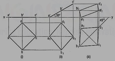
In the initial stage, assume the square to be lying in the H.P. With AC parallel to the V.P.
(i) Draw the top view and the front view. When the square is tilted about the corner A so that AC makes 30° angle with the H.P., BO remains perpendicular to the V.P. And parallel to the H.P.
(ii) Draw the second front view with a'c' inclined at 30° to xy, keeping a' or c' in xy. Project the second top view. The square may now be turned so that BO makes 45° angle with the V.P. And remains parallel to the H.P. Only the position of the top view will change. Its shape and size will remain the same.
(iii) Reproduce the top view so that b1d1 is inclined at 45° to xy. Project the final front view upwards from this top view and horizontally from the second front view.
2. Draw the projections of a circle of 50 mm diameter resting in the H.P. On a point A on the circumference, its plane inclined at 45° to the H.P. And
(a) the top view of the diameter AB making 30° angle with the V.P.;
(b) the diameter AB making 30° angle with the V. P.
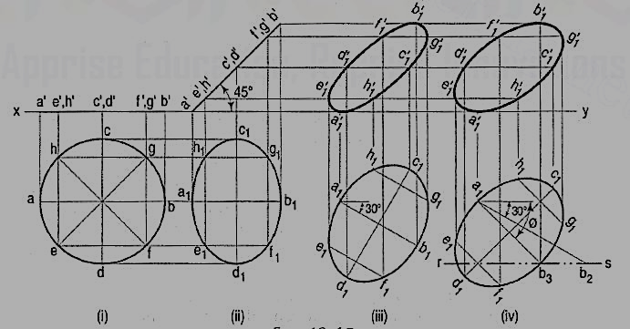
Draw the projections of the circle with A in the H.P. And its plane inclined at 45° to the H.P. And perpendicular to the V.P. [fig.(i) and fig.(ii)].
(a) In the second top view, the line a1b1 is the top view of the diameter AB. Reproduce this top view so that a1b1 makes 30° angle with xy [fig. 12(iii)]. Project the required front view.
(b) If the diameter AB, which makes 45° angle with the H.P., is inclined at 30° to the V.P. Also, its top view a1b1 will make an angle greater than 30° with xy. This apparent angle of inclination is determined as described below.
Draw any line a1b2 equal to AB and inclined at 30° to xy [fig. (iv)]. With a1 as center and radius equal to the top view of AB, viz. a1b1, draw an arc cutting rs (the path of B in the top view) at b3. Draw the line joining a1 with b3, and around it, reproduce the second top view. Project the final front view. It is evident that a1b3 is inclined to xy at an angle ϕ which is greater than 30°.
3. A thin 30°-60° set-square has its longest edge in the V.P. And inclined at 30° to the H.P. Its surface makes an angle of 45° with the V.P. Draw its projections.
In the initial stage, assume the set-square to be in the V.P. With its hypotenuse perpendicular to the H.P.
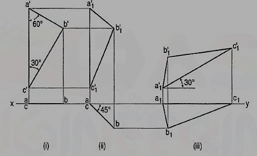
(i) Draw the front view a'b'c' and project the top view ac in xy.
(ii) Tilt ac around the end a so that it makes 45° angle with xy and project the front view a'1b'1c'1.
(iii) Reproduce the second front view a'1b'1c'1 so that a'1b'1 makes an angle of 30° with xy. Project the final top view a1b1c1.