GUJARAT TECHNOLOGICAL UNIVERSITY
WAVES, MOTION AND ACOUSTICS
MODULE 2
CONTENT
Simple Harmonic Motion or SHM is defined as a motion in which the restoring force is directly proportional to the displacement of the body from its mean position. The direction of this restoring force is always towards the mean position.
Simple harmonic motion can be described as an oscillatory motion in which the acceleration of the particle at any position is directly proportional to the displacement from the mean position. It is a special case of oscillatory motion.
All the Simple Harmonic Motions are oscillatory and also periodic but not all oscillatory motions are SHM. Oscillatory motion is also called the harmonic motion of all the oscillatory motions wherein the most important one is simple harmonic motion (SHM).
In this type of oscillatory motion displacement, velocity and acceleration and force vary (w.r.t time) in a way that can be described by either sine (or) the cosine functions collectively called sinusoids.
Simple Harmonic Motion
When a particle moves to and fro about a fixed point (called equilibrium position) along with a straight line then its motion is called linear Simple Harmonic Motion.
For Example: spring-mass system
Conditions for Linear SHM:
The restoring force or acceleration acting on the particle should always be proportional to the displacement of the particle and directed towards the equilibrium position.
F∝−x
a∝−x
x – displacement of particle from equilibrium position.
F – Restoring force
A – acceleration
Let us consider a simplest mechanical system executing simple harmonic motion. We will solve differential equation for SHM.
MECHANICAL SIMPLE HARMONIC OSCILLATORS
The figure-1 depicts simple mechanical oscillator having mass attached to the spring. This structure is similar to Pendulum. It is also known as harmonic oscillator.
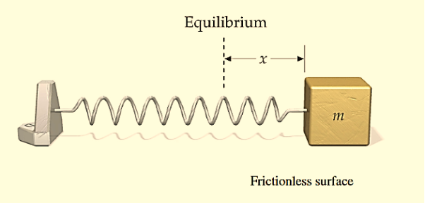
Figure: 1
If a body attached to a spring is displaced from its equilibrium position, the spring exerts a restoring force on it, which tends to restore the object to the equilibrium position. This force causes oscillation of the system, or periodic motion.
When the restoring force is directly proportional to the displacement from equilibrium, the resulting motion is known as simple harmonic motion and the oscillator is known as Harmonic Oscillator.
In this type of system body itself changes its position.
For mechanical oscillation two things are especially responsible i.e. Inertia & Restoring force.
Differential Equation
A particle is said to be execute simple harmonic oscillation is the restoring force is directed towards the equilibrium position and its magnitude is directly proportional to the magnitude and displacement from the equilibrium position. If F is the restoring force on the oscillator when its displacement from the equilibrium position is x, then
F –x
–x
Here, the negative sign implies that the direction of restoring force is opposite to that of displacement of body i.e. towards equilibrium position.
F= -kx ............. (1)
Where, k= proportionality constant called force constant.
An example of such a simple system is the mass m, attached to a spring of stiffness k.
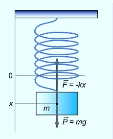
Figure: 2
In the case of a mass on a spring, the restoring force for small oscillations obeys Hooke’s law:
F=−kx ………….(1)
Where k is the stiffness of the spring. Here the coordinate x=0 corresponds to the point of equilibrium, in which the force of gravity is balanced by the initial tension of the spring.
Then, according to Newton’s second law
F= ma = m  ………….(2)
From equation (1) and (2)
m  = −kx
= −kx
m  + kx = 0
 +
+  x = 0 ………….(3)
Equation (3) can also be written as
⇒x′′+ x = 0
x = 0
 + ω2x = 0 ………….(4)
Or
⇒x′′+ ω2x=0
On comparing equation (3) and (4)
ω2 = 
ω= ………….(5)
Solution of differential equation is
x= Acosωt ………….(4)
Thus, the mass on the spring will perform undamped harmonic oscillations with the circular frequency
ω=
The period of oscillation, respectively, will be equal to
T=  = 2π
= 2π 
A similar analysis of other oscillatory system which execute Simple harmonic motion. a simple pendulum – leads to the following formula for the oscillation period:
T=2π 
Where L is the length of the pendulum, g is the acceleration of gravity.
In the case of a compound or physical pendulum, the period of oscillation is given by
T=2π 
Where I is the moment of inertia of the pendulum about the pivot point, m is the mass of the pendulum, a is the distance between the pivot point and the center of mass of the pendulum.
Example: oscillation of mass spring system, oscillation of fluid-column in a U-tube, oscillation of simple pendulum, rotation of earth around the sun, oscillation of body dropped in a tunnel along earth diameter, oscillation of floating cylinder, oscillation of a circular ring suspended on a nail, oscillation of atoms and ions of solids, vibration of swings etc.
Vibration is periodic back-and-forth motion of the particles of an elastic body or medium, commonly resulting when almost any physical system is displaced from its equilibrium condition and allowed to respond to the forces that tend to restore equilibrium.
Free Vibrations
Definition- A system is said to execute free vibrations if on being disturbed from its position of equilibrium, it vibrates itself without outside interference
Free vibrations occur when the system is disturbed momentarily and then allowed to move without restraint. A classic example is provided by a weight suspended from a spring. In equilibrium, the system has minimum energy and the weight is at rest. If the weight is pulled down and released, the system will respond by vibrating vertically.
A free vibration is where there is no externally applied vibration forcing. The solution to a free vibration is usually roughly sinusoidal. Of course, vibrations can occur across a whole spectrum of frequencies. There will usually be one or more frequencies where there is growing amplitude. At the limit of stability, a free vibration has constant amplitude. It neither grows nor decays.
The vibrations of a spring are of a particularly simple kind known as simple harmonic motion (SHM). This occurs whenever the disturbance to the system is countered by a restoring force that is exactly proportional to the degree of disturbance. In this case, the restoring force is the tension or compression in the spring, which (according to Hooke’s law) is proportional to the displacement of the spring. In simple harmonic motion, the periodic oscillations are of the mathematical form called sinusoidal. One characteristic of SHM is that the period of the vibration is independent of its amplitude.
Forced vibrations
Definition- A system is said to execute forced vibrations when it is compelled or forced to vibrate with a frequency other than its natural frequency.
Forced vibrations occur if a system is continuously driven by an external agency. A simple example is a child’s swing that is pushed on each downswing. Of special interest are systems undergoing SHM and driven by sinusoidal forcing.
We have learnt that the amplitude of the oscillations of a system or a body executing damped simple harmonic oscillator goes on decreasing and ultimately vanish with the passage of time. The oscillation of such a body can be maintained by applying an external periodic force.
When a body vibrates by being influenced by an external periodic force, it is called forced vibrations Here, the amplitude of vibrations, experiences damping but remains constant due to the external energy supplied to the system.
Sinusoidal vibration forcing of a stable system produces steady vibration amplitude. However, if the system is forced with a frequency at the limit of stability, vibration amplitude will grow to infinity or until limited by non-linearity. We may therefore consider limiting stability to be unstable in practice.
For example – A child’s swing comes to rest unless external force applied at proper and regular interval of time to make the swing keep on swinging with a large amplitude. The same is the case with a pendulum or a vibrating mass attached to a spring. The applied periodic force is called the Driving Force and the oscillating system is called the Driven Oscillator.
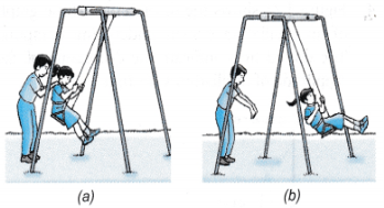
Figure: 3
Resonance
Resonance occurs when:-
Frequency of the external periodic force = Natural frequency of the system.
Definition:- The phenomena of producing vibratory motion in a system by the influence of an external periodic force having the same frequency as that of natural frequency of the system is called Resonance.
Free vibrations are oscillations where the total energy stays the same over time. This means that the amplitude of the vibration stays the same. This is a theoretical idea because in real systems the energy is dissipated to the surroundings over time and the amplitude decays away to zero, this dissipation of energy is called damping.
Example:- Resonance causes disaster during earthquake. When the natural frequency of the building becomes equal to the frequency of the periodic vibration present in the earth during earthquake, then the building starts vibrating with large amplitude and hence it collapses.
Undamped Vibration
Undamped Vibration refers to vibrations where energy of the vibrating object does not get dissipated to surroundings over time.
If there is no external force applied on the system, f(t) =0, the system will experience free vibration. Motion of the system will be established by an initial disturbance (i.e. initial conditions).
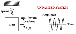
Figure: 4
Furthermore, if there is no resistance or damping in the system, the oscillatory motion will continue forever with constant amplitude. Such a system is termed undamped.
Damped Vibration
When the energy of a vibrating system is gradually dissipated by friction and other resistances, the vibrations are said to be damped. The vibrations gradually reduce or change in frequency or intensity or cease and the system rests in its equilibrium position.
Damped vibration refers to vibrations where the vibrating object loses its energy to the surroundings.
Damping, in physics, restraining of vibratory motion, such as mechanical oscillations, noise, and alternating electric currents, by dissipation of energy. Unless a child keeps pumping a swing, its motion dies down because of damping. Shock absorbers in automobiles and carpet pads are examples of damping devices.
A system may be so damped that it cannot vibrate. Critical damping just prevents vibration or is just sufficient to allow the object to return to its rest position in the shortest period of time.
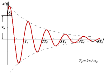
Figure: 5
There are many types of mechanical damping. Friction, also called in this context dry, or Coulomb, damping, arises chiefly from the electrostatic forces of attraction between the sliding surfaces and converts mechanical energy of motion, or kinetic energy, into heat. The motion of a vibrating body is also checked by its friction with the gas or liquid through which it moves.
Damped Oscillations
In real systems, there is always a resistance or friction, which leads to a gradual damping of the oscillations. In many cases, the resistance force (denoted by FC) is proportional to the velocity of the body, that is
FC=−cx′.
Then, taking into account the force of resistance, the differential equation for the “mass-spring” system is written as
Mx′′+cx′+kx=0, ⇒ x′′+  x′+
x′+ x=0
x=0
We introduce the following notations:  =2β,
=2β,  =
=  . Here ω0 is the natural frequency of the undamped oscillator (previously, we denoted it as ω), β is the damping coefficient. In the new notations, the differential equation looks like
x′′+2βx′+ x=0.
x=0.
We will seek the solution of this equation as a function
x(t)=Aeλt.
The derivatives are given by
x′(t)=Aλeλt, x′′(t)=Aλ2eλt.
Substituting this into the differential equation, we obtain the algebraic characteristic equation:
Aλ2eλt+2βAλeλt+ Aeλt=0,
⇒λ2+2βλ+ =0.
=0.
The roots of this equation are
D=4β2−4 ,
,

It can be seen that depending on the sign of the radicand β2− , there may be three different types of solutions.
Case 1. Overdamping or Heavy Damping: β>ω0
When resistance to motion is.very strong, the system is said to be heavily damped. Can you name a heavily damped system of practical interest? Springs joining wagons of a train constitute the most important heavily damped system. In your physics laboratory, vibrations of a pendulum in a viscous medium such as thick oil and motion of the coil of a dead beat galvanometer are heavily damped systems.
In this case (the case of strong damping), the radicand is positive: β2> . The roots of the characteristic equation are real and negative. The general solution of the differential equation has the form
x(t)=C1eλ1t+C2eλ2t,
Where the coefficients C1, C2, as usual, depend on the initial conditions.
It follows from this expression that there are no oscillations and the system returns to equilibrium exponentially, i.e. aperiodically (Figure 9).
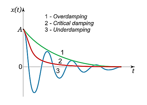
Figure 6
Case 2. Critical Damping: β=ω0
You may have observed that on hitting an isolated road bump, a car bounces up and down and the occupants feel uncomfortable. To minimise this discomfort, the bouncing caused by the road bumps must be damped very rapidly and the automobile is restored to equilibrium quickly. For this we use critically damped shock absorbers. Critical damping is also useful in recording instruments such as a galvanometer (pointer type as well as suspended coil type) which experience sudden impulses. We require the pointer to move to the correct position in minimum time and stay there without executing oscillations. Similarly, a ballistic galvanometer coil is required to return to zero displacement immediately.
In the limiting case when β=ω0, the roots of the characteristic equation are real and coincide:
λ1=λ2=−β=−ω0.
Here the solution is given by the formula
x(t)=(C1t+C2)
In this mode, the value of x(t) may even increase at the beginning of the process because of the linear factor C1t+C2. But in the end the deflection x(t) decreases rapidly due to the exponential decay with a characteristic time τ=2π/ω0.
Note that in this critical mode the relaxation occurs faster than in the case of the aperiodic damping (Case 1). Indeed, in this mode the relaxation time will be determined by the smaller (in absolute value) root λ1, and will be given by the formula

The function Φ(β/ω0) included in this expression is monotonically increasing. It is always greater than or equal to 1, as shown in Figure 10

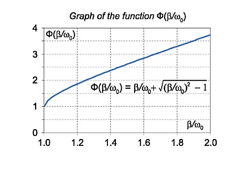
Figure: 7
In the critical case (Case 2) the ratio βω0 is 1, and βω0>1 in the case of the aperiodic damping (Case 1). Therefore for the aperiodic damping mode, we can write
τ= Φ(
Φ( ) >
) > 
Thus, the critical damping mode provides the fastest possible return of the system to equilibrium. This is often used, for example, in door closing mechanisms.
Case 3. Underdamping or Light Damping β<ω0
Here the roots of the characteristic equation are complex conjugate:
λ1,2 =−β±i√
The general solution of the differential equation is oscillatory in nature and can be written as
x(t)=e−βt[C1cos(ω1t)+C2sin(ω1t)]
Where the oscillation frequency ω1 is equal to
ω1= 
The resulting formula can be written in a somewhat different form:
x(t)=Ae−βtcos(ω1t+φ0),
Where φ0 is the initial phase of the oscillations and Acosφ0 is the initial amplitude of the oscillations. We see that classical damped oscillations occur in this mode. Here the oscillation frequency ω1 is less than the harmonic frequency ω0, and the oscillation amplitude decreases exponentially with e−βt.
Forced vibration without damping
Force Applied to Mass. When the sinusoidal force F=F0sinωt is applied to the mass of the undamped single degree-of-freedom system shown in Figure 8.
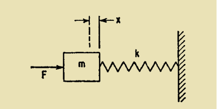
Figure 8: Undamped single degree-of-freedom system excited in forced vibration by force acting on mass.
The differential equation of motion is
m +kx=F0sinωt ..………..(1)
The solution of this equation is
X = Asinωnt + Bcosωnt+  sinωt ..………..(2)
Where ωn= 
The first two terms represent an oscillation at the undamped natural frequency ωn. The coefficient B is the value of x at time t=0, and the coefficient A may be found from the velocity at time t=0.
Differentiating Equation (2) and setting t=0,
 (0)=Aωn+
 …………..(3)
The value of A is found from Equation (3).
The oscillation at the natural frequency ωn gradually decays to zero in physical systems because of damping. The steady-state oscillation at forcing frequency ω is
x= sinωt ……………(4)
This oscillation exists after a condition of equilibrium has been established by decay of the oscillation at the natural frequency ωn and persists as long as the force F is applied.
The force transmitted to the foundation is directly proportional to the spring deflection: Ft=kx. Substituting x from Equation (4) and defining transmissibility T=Ft/F,
T=  ……….…(5)
If the mass is initially at rest in the equilibrium position of the system (i.e., x=0 and  =0) at time t=0, the ensuing motion at time t>0 is
x= (sinωt−
  sinωnt) …………(6)
For large values of time, the second term disappears because of the damping inherent in any physical system, and Equation (6) becomes identical to Equation (4).
When the forcing frequency coincides with the natural frequency, ω=ωn and a condition of resonance exists. Then Eq. (6) is indeterminate and the expression for x may be written as
X =−  cos ωt+
 sin ωt ……………(7)
According to Equation (7), the amplitude x increases continuously with time, reaching an infinitely great value only after an infinitely great time.
Motion of Foundation
The differential equation of motion for the system of Figure 9 excited by a continuing motion u=u0sinωt of the foundation is
m = −k(x−u0sin ωt)
The solution of this equation is

Where ωn=k/m and the coefficients A1,B1 are determined by the velocity and displacement of the mass, respectively, at time t=0. The terms representing oscillation at the natural frequency are damped out ultimately, and the ratio of amplitudes is defined in terms of transmissibility T:
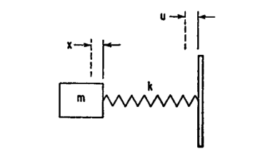
Figure 9: Undamped single degree-of-freedom system excited in forced vibration by motion of foundation.
 = T = T=
Where x=x0sinωt.Thus, in the forced vibration of an undamped single degree-of-freedom system, the motion response, the force transmissibility, and the motion transmissibility are numerically equal.
Forced vibration with viscous damping
Force Applied to Mass.
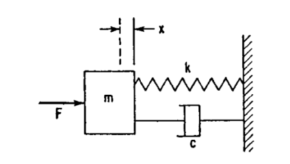
Figure 10: Single degree-of-freedom sys-tem with viscous damping, excited in forced vibration by force acting on mass
The differential equation of motion for the single degree-of-freedom system with viscous damping shown in Figure 10, when the excitation is a force F=F0sinωt applied to the mass, is
m +c
+c kx=F0sinωt ..………..(8)
Equation (8) corresponds to Equation (1) for forced vibration of an un-damped system; its solution would correspond to Eq. (2) in that it includes terms representing oscillation at the natural frequency. In a damped system, however, these terms are damped out rapidly and only the steady-state solution usually is considered. The resulting motion occurs at the forcing frequency ω; when the damping coefficient c is greater than zero, the phase between the force and resulting motion is different than zero. Thus, the response may be written
x=Rsin(ωt−θ) =A1sin ωt+B1cos ωt ..………..(9)
Substituting this relation in Eq. (8), the following result is obtained:
 ..………..(10)
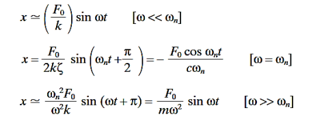
And Rd is a dimensionless response factor giving the ratio of the amplitude of the vibratory displacement to the spring displacement that would occur if the force F were applied statically. At very low frequencies Rd is approximately equal to 1; it rises to a peak near ωn and approaches zero as ω becomes very large. The displacement response is defined at these frequency conditions as follows:
 ..………..(11)
For the above three frequency conditions, the vibrating system is sometimes described as spring-controlled, damper-controlled, and mass-controlled, respectively, depending on which element is primarily responsible for the system behaviour. Curves showing the dimensionless response factor Rd as a function of the frequency ratio ω/ωn are plotted in Figure 11 on the coordinate lines having a positive 45° slope. Curves of the phase angle θ are plotted in Figure 12. A phase angle between 180 and 360°cannot exist in this case since this would mean that the damper is furnishing energy to the system rather than dissipating it. An alternative form of Equations (10) and (11) is
 …………..(12)
This shows the components of the response which are in phase [(Rd)xsin ωt] and 90°out of phase [(Rd)Rcosωt] with the force. Curves of (Rd)x and (Rd)R are plotted as a function of the frequency ratio ω/ωn in Figures 13 and 14.
Velocity and Acceleration Response
The shape of the response curves changes distinctly if velocity ̇x or acceleration ̈x is plotted instead of displacement x. Differentiating Equation (10),
 ………………(13)
The acceleration response is obtained by differentiating Equation (13)

……………….(14)
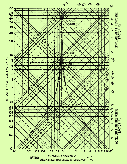
Figure: 11
Response factors for a viscous-damped single degree-of-freedom system excited in forced vibration by force acting on the mass. The velocity response factor shown by horizontal lines is defined by Eq. (13); the displacement response factor shown by diagonal lines of positive slope is defined by Eq. (10); and the acceleration response factor shown by diagonal lines of negative slope is defined by Equation (14).
The velocity and acceleration response factors defined by Equations. (13) and (14) are shown graphically in Figure 11, the former to the horizontal coordinates and the latter to the coordinates having a negative 45°slope. Note that the velocity response factor approaches zero as ω→0 and ω→∞, whereas the acceleration response factor approaches 0 as ω→0 and approaches unity as ω→∞
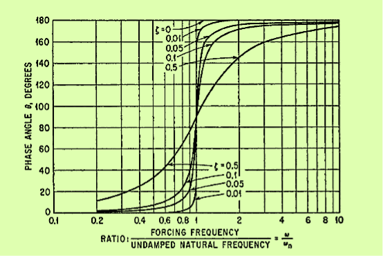
Figure 12:
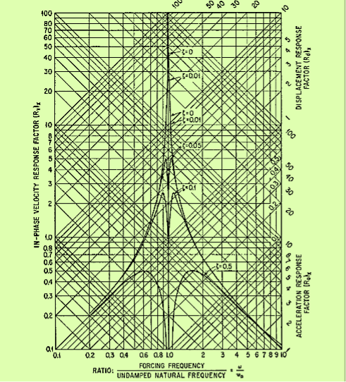
Figure 13: In-phase component of response factor of a viscous-damped system in forced vibration. All values of the response factor for ω/ωn>1 are negative but are plotted without regard for sign. The fraction of critical damping is denoted by ζ.
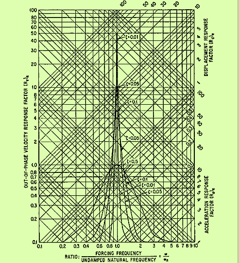
Figure 14: Out-of-phase component of response factor of a viscous-damped system in forced vibration. The fraction of critical damping is denoted by ζ.
Resonance Frequencies
The peak values of the displacement, velocity, and acceleration response of a system undergoing forced, steady-state vibration occur at slightly different forcing frequencies. Since a resonance frequency is defined as the frequency for which the response is a maximum, a simple system has three resonance frequencies if defined only generally. The natural frequency is different from any of the resonance frequencies. The relations among the several resonance frequencies, the damped natural frequency, and the undamped natural frequency ωn are:
Displacement resonance frequency: ωn(1 −2ζ2)1/2
Velocity resonance frequency: ωn
Acceleration resonance frequency: ωn/(1 −2ζ2)1/2
Damped natural frequency: ωn(1 −ζ2)1/2
For the degree of damping usually embodied in physical systems, the difference among the three resonance frequencies is negligible
Energy Intake
When the viscous damped, single degree-of-freedom system shown in Figure 10 undergoes vibration defined by
x=x0sin ωt ……………(15)
The net force exerted on the mass by the spring and damper is
F=kx0sin ωt+cωx0cos ωt ……………(16)
Equations (15) and (16) define the relation between F and x; this relation is the ellipse shown in Figure 15.
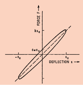
Figure 15: Hysteresis curve for a spring and viscous damper in parallel.
The energy dissipated in one cycle of oscillation is
W = =πcω
=πcω
In physics a wave can be thought of as a disturbance or oscillation that travels through space-time accompanied by a transfer of energy. Wave motion transfers energy from one point to another, often with no permanent displacement of the particles of the medium —that is with little or no associated mass transport.
The emphasis of the last point highlights an important misconception of waves. Waves transfer energy not mass.
A wave is a vibratory disturbance in a medium which carries energy from one point to another point without any actual movement of the medium. There are three types of waves
- Mechanical Waves Those waves which require a material medium for their propagation, are called mechanical waves, e.g., sound waves, water waves etc.
- Electromagnetic Waves Those waves which do not require a material medium for their propagation, are called electromagnetic waves, e.g., light waves, radio waves etc.
- Matter Waves These waves are commonly used in modern technology. These waves are associated with electrons, protons and other fundamental particles.
There are two types of waves:
- Longitudinal waves
- Transverse waves
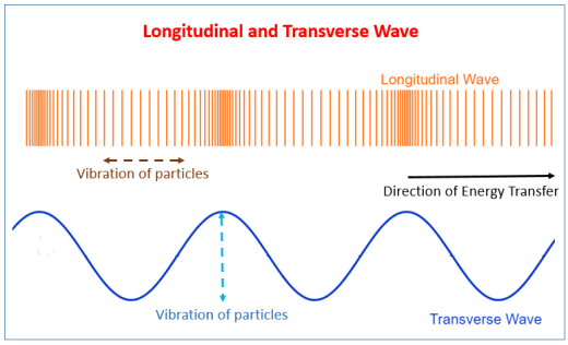
Figure: 16
Longitudinal Waves: A wave in which the particles of the medium vibrate back and forth in the ‘same direction’ in which the wave is moving. Medium can be solid, liquid or gases. Therefore, sound waves are longitudinal waves. These waves travel in the form of compressions and rarefactions.
Longitudinal waves have the same direction of vibration as their direction of travel. This means that the movement of the medium is in the same direction as the motion of the wave. Some longitudinal waves are also called compressional waves or compression waves. An easy experiment for observing longitudinal waves involves taking a Slinky and holding both ends. After compressing and releasing one end of the Slinky (while still holding onto the end), a pulse of more concentrated coils will travel to the end of the Slinky. In the example of the Slinky, each coil will oscillate at a point but will not travel the length of the Slinky. It is important to remember that energy, in this case in the form of a pulse, is being transmitted and not the displaced mass.
Longitudinal waves can sometimes also be conceptualized as pressure waves. The most common pressure wave is the sound wave. Sound waves are created by the compression of a medium usually air. Longitudinal sound waves are waves of alternating pressure deviations from the equilibrium pressure, causing local regions of compression and rarefaction. Matter in the medium is periodically displaced by a sound wave, and thus oscillates. When people make a sound, whether it is through speaking or hitting something, they are compressing the air particles to some significant amount. By doing so, they create transverse waves. When people hear sounds, their ears are sensitive to the pressure differences and interpret the waves as different tones.
Transverse Waves: A wave in which the particles of the medium vibrate up and down ‘at right angles’ to the direction in which the wave is moving. These waves are produced only in a solids and liquids but not in gases. These waves travel in the form of crests and troughs. If a transverse wave is moving in the positive x-direction, its oscillations are in up and down directions that lie in the y–z plane. Light is an example of a transverse wave. For transverse waves in matter, the displacement of the medium is perpendicular to the direction of propagation of the wave. A ripple on a pond and a wave on a string are easily visualized transverse waves.
Transverse waves are waves that are oscillating perpendicularly to the direction of propagation
Wave can be described by following characteristics:
- Wavelength
- Amplitude
- Time-Period
- Frequency
- WAVELENGTH
The distance between the centres of two consecutive compressions or two consecutive rarefactions is equal to its wavelength.
It is denoted by a Greek letter λ (lambda). The S.I unit for measuring wavelength is metre (m).
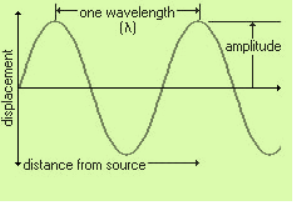
Figure 17 :Wavelength of wave
The minimum distance in which a sound wave repeats itself is called its wavelength. That is it is the length of one complete wave. We know that in a sound wave, the combined length of a compression and an adjacent rarefaction is called its wavelength.
The distance between the centres of a compression and an adjacent rarefaction is equal to half of its wavelength i.e. λ/2.
- AMPLITUDE
When a wave passes through a medium, the particles of the medium get displaced temporarily from their original undisturbed positions and the maximum displacement of the particles of the medium from their original undisturbed positions is called amplitude of the wave.
The S.I unit of measurement of amplitude is metre (m) though sometimes it is also measured in centimetres.
Amplitude is used to describe the size of the wave. The amplitude of a wave is the same as the amplitude of the vibrating body producing the wave.
- TIME-PERIOD
The time required to produce one complete wave or cycle is called time-period of the wave.
It is denoted by letter T. The unit of measurement of time-period is second (s).
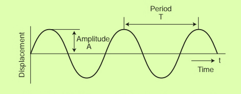
Figure 18 :Time period of wave
One complete wave is produced by one full vibration of the vibrating body. So, we can say that the time taken to complete one vibration is known as time-period
- FREQUENCY
The number of complete waves or cycles produced in one second is called frequency of the wave.
The frequency of a wave is denoted by the letter f. The S.I unit of frequency is hertz written as Hz. Bigger unit of frequency is known as kilohertz (kHz). 1 kHz = 1000 Hz.
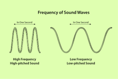
Figure 19: Frequency of sound wave
Since one complete wave is produced by one full vibration of the vibrating body so we can say that the number of vibrations per second is called frequency. A vibrating body emitting 1 wave per second is said to have a frequency of 1 hertz. That is 1Hz is equal to 1 vibration per second.
Frequency of a wave is fixed and does not change even when it passes through different substances. The frequency of a wave is the same as the frequency of the vibrating body which produces the wave.
For example: if 20 complete waves or vibrations are produced in one second then the frequency of the waves will be 20 hertz or 20 cycles per second.
What is the relation between time-period and frequency of a wave?
The time required to produce one complete wave is called time-period of the wave. Suppose the time-period of a wave is T seconds.
In T seconds number of waves produced = 1
So, in 1 second, number of waves produced will be = 1/T
But the number of waves produced in 1 second is called its frequency.
Therefore, F = 1/Time-period
f = 1/T
where f = frequency of the wave
T = time-period of the wave
SOUND ABSORPTION
The coefficient of absorption of material is defined as the ratio of the sound energy absorbed by the surface to that of the total incident sound energy on the surface.
Absorption Coefficient = 
As all sound waves falling on an open window pass through, it can be assumed that an open window behaves as perfect absorber of sound and hence the standard of absorption is taken as the unit area of an open window as a standard unit of absorption.
Thus, the absorption coefficient of a material is defined as the rate of the sound energy absorbed by a certain area of the surface to that of open window of same area.
The absorption coefficient of a surface is defined as the reciprocal of its area which absorbs the same sound energy absorbed at a unit area of an open window.
REVERBERATION
Reverberation and Time of Reverberation
When a sound is produced in a building, it lasts too long after its production. It reaches to the listener a number of times. Once it reaches directly from the source and subsequently after reflection from the walls, windows, ceiling and flour of hall. The listener therefore receives series of sounds of diminishing intensity. By reverberation is meant the prolonged reflection of sound from the walls, floor and ceiling of a room.
The reverberation is defined as the persistence of audible sound after the source has stopped to emit sound. The duration for which the sound is stopped is called reverberation time. This time is measured from the instant the source stops emitting sound.
The time of reverberation is defined as the time taken by the sound to fall below the minimum audibility measured from the instant when the source stopped emitting sound.
According to Prof. W. C. Sabine, the standard reverberation time is defined as the time taken by sound to fall to one millionth of its intensity just before the sound is cut off.
According to W. C. Sabine, the time of reverberation depends up on
1. Size of hall,
2. Loudness of the sound,
3. Kind of music or sound for which hall is to be used.
Acoustics and Ultrasonic Reverberation Time
T = 0.165 V/
T = 0.165 V/ A
Where V-Volume of hall in m3
a - Absorption coefficient
S - Area of reflecting surface in a square meter
 Absorption of hall.
Acoustically good hall we mean that in which every syllable or musical note reaches an audible level of loudness at every point of the hall and then quickly dies away to make room ready for the next syllable or group of notes. Following are the factors affecting architectural acoustics.
- REVERBERATION
In a hall, if the reverberation is large there is of successive sounds which result in loss of clarity in hearing. However if the reverberation is very small, the loudness is inadequate Thus the time of reverberation for a hall should neither too large nor too small. The preferred value of the time of reverberation is called optimum the reverberation time. According to W. C. Sabine standard reverberation time is given by:
T = 0.165 V/
T = 0.165 V/ A
Where V-Volume of hall in m3
a - Absorption coefficient
S - Area of reflecting surface in a square meter
 Absorption of hall
The reverberation can be controlled by the following factors:
- By providing windows and ventilators which can be opened and closed to make the optimum time of reverberation
- Decorating the walls by pictures and maps
- Using heavy curtains with folds
- The walls are lined with absorbent material such as felt, fibreboard, glass wool etc.
- Having full capacity of audience
- By covering floor with carpet
- By providing acoustics tiles
2. ADEQUATE LOUDNESS
With large absorption the time of reverberation will be smaller which will minimize the chances of confusion and may go below the level of intelligibility of hearing. Hence sufficient loudness in every portion of the hall is an important factor for satisfactory hearing.
The loudness can he maintained at desired level by:
Using large sounding boards behind the speaker and facing the audience.
Large polished wooden reflecting surfaces immediately above the speakers.
Low ceiling are also useful in reflecting the sound energy towards the audience.
By providing additional sound energy using more number of speakers
3. FOCUSING DUE TO WALLS AND CEILINGS
If there are focusing surfaces like concave, spherical, cylindrical or parabolic etc. on the walls or ceiling or the floor of the hall, they produce concentration of the sound in to particular region, while in some other parts no sound reaches at all. Thus there will be non- uniformity in the distribution of sound energy in the hall.
For uniform distribution of sound in the hall:
- There should be no curved surfaces. If such surfaces are present, they should be covered with absorbent material.
- Ceiling should be low.
- Arrange speaker at the focus of parabolic reflecting surface. This will helpful to reflect beam of sound in the hall.
4. ECHOES
An echo is heard, when direct and reflected sound waves coming from the same source reach the listener with time interval of about  th second. It should be avoided as far as possible by absorption.
Echoes can he avoided by:
- Covering long distant walls with curtain or absorbent material
- Covering high ceiling with absorbent material
5. ECHELON EFFECT
A set of railings, pillars or any regular spacing of reflected surfaces may produce a musical note due to regular succession of the echoes of the original sound to the listener. This makes the original sound confused.
This can be avoided by:
- Covering steps with carpet
- Covering flour with carpet
- Avoid pillars in the hall
6. BALCONIES
There are chances of reflection of sound from the railing of balcony. This may lead to the problem like echelon effect or echoes.
This can be eliminated by:
- Adjust height to depth ratio as 2: 1
- Use grills and bars for railings instead of bricks
7. SEATING ARRANGEMENT
This is one of the factors to be taken care at the time of arranging the seats.
It preferred to arrange:
- Seats perpendicular to the direction of sound for better audibility
- Seats must be gradually elevated to take care of absorption of sound energy by human body.
8. EXTRANEOUS NOISE AND SOUND INSULATION
In a good hall no noise should reach from outside. Noise may be defined as unwanted sound such as:
Outside Noise: street traffic, hammering, drilling, operating machinery, moving of furniture, electrical generator etc.
Inside Noise: machinery, typewriters, telephone, mobiles, projector etc.
This extraneous noise can be avoided by:
- Avoiding openings for pipes and ventilators
- Allotting suitable locations for doors and windows
- Using heavy glasses to doors and windows
- By providing double wall construction with air space between them
- By interposing layers of some acoustical insulators
- Use of soft floor finish e.g. Carpet, rubber etc.
- Insulating machines like refrigerators, lifts, typewriters, projector etc.
- Constructing small sound proof cabin for machine and office staff
- Making hall sound proof
9. FREEDOM FROM RESONANCE
If the frequency of the created sound is equal to original sound, then the original music will be reinforced. Due to the interference between original sounds is distorted. Enclosed air in the hall also causes resonance.
This can be avoided by:
- Using absorbing material on reflecting surfaces
- Providing decoration which include holes in the design on interior wall
- Using ventilators whenever necessary