GUJARAT TECHNOLOGICAL UNIVERSITY
ULTRASONIC AND NON DISTRACTIVE TESTING (NDT)
MODULE 3
CONTENT
ULTRASONIC WAVE
Ultra (meaning beyond) + sonic (meaning sound) = beyond the audible sound range i.e. 20kHZ
As we know Sound wave is a vibration that can be transmitted through a medium like air, water, and metals. Whereas Ultrasonic wave is defined as inaudible sound with high frequency of range more than 20 kHz which is actually higher than the upper audible limit of human hearing.A healthy body can hear soundwave of frequency approximately 20 kilohertz. Also this range can vary from human to human.
In other words Sound wave which is not intended to be heard by human is also called ultrasonic wave.
Generally these waves are called as high frequency waves
Sound wave is a vibration that is transmitted through a medium, such as air, water, and metals. Ultrasonic wave is defined as “inaudible sound with high frequency for human” the frequency of which generally exceeds 20 kHz. These days, sound wave which is not intended to be heard is also called ultrasonic wave.
Longitudinal wave and transverse wave
There are types of ultrasonic waves, longitudinal wave, transverse wave and surface wave, etc.
In a solid, there simultaneously exist two types of elastic waves. One is an elastic wave that has a displacement in the same direction of the propagation direction of the wave called longitudinal wave or density wave and another is an elastic wave that has a displacement to the vertical direction of the propagation direction of the wave called traverse wave or shear wave.
Our ultrasonic processing machine mainly uses the longitudinal wave.
Longitudinal wave

Figure:1
Where R is Rarefaction and C is Compression.
Transverse wave

Figure:2
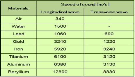
The following table shows physical property of longitudinal wave and
Transverse wave of the main material.
Table:1
- The ultrasonic waves cannot travel through vacuum.
- These waves travel with speed same as sound wave travel in any given medium.
- In homogeneous medium the velocity of ultrasonic wave is constant.
- These waves can also weld some material like plastics and metals.
- They have high energy content.
- Ultrasonic waves get reflected, refracted and absorbed just like sound waves.
- They can be transmitted over large distances without any appreciable loss of energy.
- They produce intense heating effect when passed through a substance.
- The ultrasonic waves have high frequency.
- Because of their smaller wavelength Ultrasonic waves produce negligible diffraction effects.
- Ultrasonic waves can produce vibrations in low viscosity liquids.
- When the ultrasonic wave is absorbed by a medium, it produces heat because of high frequency and high energy and that energy is used to drill and cut thin metals.
Production of Ultrasonic Wave
Ultrasonic waves are produced by the following methods.
- Magneto-striction generator or oscillator
- Piezo-electric generator or oscillator
PIEZOELECTRIC EFFECT
In Piezoelectric “Piezo” derived from the Greek word “piezein” and the meaning of piezein is squeeze or press. So its name itself explaining the effect.
Direct Piezoelectric Effect
The piezoelectric effect transforms kinetic or mechanical energy into electrical energy, due to crystal deformation. When material is compressed or squeezed, this Mechanical stress applied to material generates electricity.
Microphones, speakers, buzzers, pressure sensors, hydrophones and many other sensing types of devices use direct piezoelectric effect.
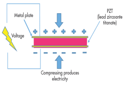
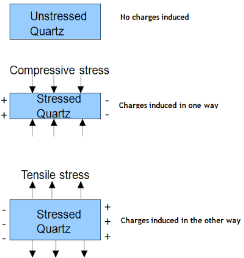
Figure:3
Above figure shows the direct piezoelectric effect
Inverse Piezoelectric Effect
We can reverse the same effect. Inverse piezoelectric effect – when electric field is applied to a crystal it align all dipoles present in the material in order. This realignment results in deformation of crystal i.e. converting electrical energy into kinetic or mechanical energy. Reversal of the piezoelectric effect is called the inverse piezoelectric effect.
Using the inverse piezoelectric effect we can develop devices that produce acoustic sound waves. Even medical ultrasound and sonar transducers use inverse piezoelectric effect.
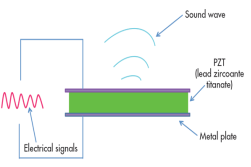
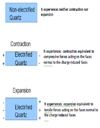
Figure:4
Above figure shows the inverse piezoelectric effect
Examples of Piezoelectric Materials
All piezoelectric materials are non-conductive in order for the piezoelectric effect to occur and work. Quartz is natural and first Piezoelectric Material whereas Lead Zirconate Titanate, Barium Titanate, and Lithium Niobate are man-made Piezoelectric Materials.
Piezoelectric Generator or Oscillator
Principle:
This is based on the Inverse piezoelectric effect. When a quartz crystal is placed under the effect of an alternating potential difference, vibrations produce in the crystal. If the frequency of electric oscillations coincides with the natural frequency of vibrations of the crystal, the vibrations will be of large amplitude. When the frequency of the electric field matches the ultrasonic frequency range, then the crystal produces ultrasonic waves.
Electric circuit :
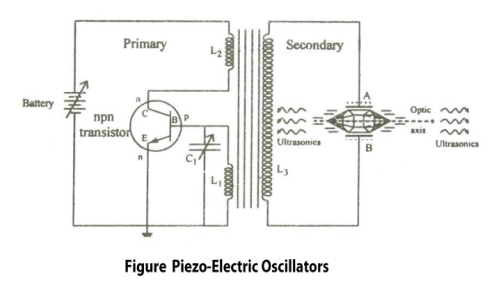
Figure:5
Construction:
- It is common base NPN oscillator circuit.
- Coils L1 and L2 are primary coils of the transformer.
- Coil L2 is connected to the collector and L1 connected to the base.
- The coil L1 and variable capacitor C1 form the tank circuit of the oscillator.
- Quartz crystal is placed between the metal plates A and B so as to form a parallel plate capacitor.
- Quartz Crystal is connected to the secondary coil L3 of the transformer through which output or ultrasonic wave is obtained.
- The frequency of the oscillations can be changed by changing the value of capacitance.
Working:
As soon as the circuit is closed, the current starts flow through the circuit and charges the capacitor. After the charging is completed the capacitor starts discharging through the inductor L1, this energy is stored in the form of electric field in capacitor C1 and in the form of magnetic field in inductor L1.
Due to this high frequency electric oscillations are produced in the tank circuit. Transistor is also produces electric oscillations. This energy or oscillations is provided to the secondary coil which is again fed to the quartz crystal. Thus oscillating electric field is converted to mechanical vibration of crystal.
When the frequency of electric oscillations is equal to that of natural frequency of the crystal, resonance is achieved and the sound waves of maximum amplitude are produced. Thus by using inverse piezoelectric effect high frequency ultrasonic waves are produced.
Condition for Resonance:
Frequency of the oscillator circuit = Frequency of the vibrating crystal

Where,
L1 is inductance of the circuit
C1 is capacitance of the circuit
t = Thickness of crystal slab
Y = Young's Modulus of material
ρ = Density of material
k = 1, 2, 3 ... (Integer Multiple)
Advantages:
- High frequency Ultrasonic waves can be produced.
- This method is more effective than the Magnetostriction oscillator.
- The output power is very high
- We are able to get a stable and constant frequency of ultrasonic waves.
- It is not affected by temperature humidity
Disadvantages:
- Quartz crystal is very costly.
- Cutting and shaping the crystal is difficult.
Principle: Magnetostriction effect: Magnetostriction is a property of magnetic materials like nickel or iron that causes them to change their shape or dimensions during the process of magnetization. i.e. when these material is placed in magnetic field parallel to its length it undergoes changes in its dimensions. This is called Magnetostriction effect.
Figure
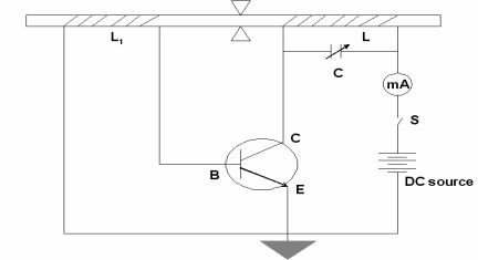
Figure:6
Construction
- In above figure we are using NPN Transistor
- In which battery is connected in such a way that emitter is forward biased and collector is reverse biased.
- Current can be produced by applying necessary biasing to the transistor with the help of the battery.
- The current produced in a circuit can be noted by the mill ammeter connected across the coil L.
- The ends of the ferromagnetic rod A and B is wound by the coils L1 and L.
- The coil L1 is connected to the base of NPN transistor The coil L is connected to the collector of the NPN transistor as shown in the figure.
- The frequency of the oscillatory circuit (LC) can be adjusted by the condenser C.
Working
The rod is initially magnetized by the DC power supply. The transistor is properly biased. The battery is switched on and hence current is produced by the transistor. This current is passed through the coil L, this current causes a change in the magnetization of the rod. Now, the rod starts vibrating due to Magnetostriction effect.
When rod is vibrating and the coil is wounded over a vibrating rod, An emf is induced in coil L, this induces an emf to coil L1 & a part of it is feed as input to the base. Hence, this feedback system makes transistor operates continuously. The e.m.f. Induced in the coil called as converse Magnetostriction effect. In this way the current is maintained in transistor so as the vibrations.
The frequency of the oscillatory circuit is adjusted by the condenser C and when this frequency is equal to the frequency of the vibrating rod, resonance occurs. At resonance, the rod vibrates longitudinally with larger amplitude producing ultrasonic waves of high frequency along both ends of the rod.
Condition for resonance
Frequency of the oscillatory circuit = Frequency of the vibrating rod

Where,
L is inductance of the circuit
C is capacitance of the circuit
l is the length of the rod.
E is the young’s modulus of the material of the rod.
ρ is the density of material of the rod.
Advantages
- This Oscillatory circuit is simple to construct.
- Magnetostrictive materials are easily available at low cost
- Large output power can be generated by using this method.
Disadvantages
- It can produce frequencies up to 3 MHz only.
- As rod depends on temperature and the degree of magnetization so it becomes difficult to get a constant single frequency.
- As the frequency is inversely proportional to the length of the vibrating rod, so if you increase the frequency, the length of the rod gets decreased which is practically impossible.
Ultrasonic waves propagated through a medium can be detected in a number of ways. Some of the methods employed are as follows:
(1) KUNDT’S TUBE METHOD
Kundt devised an experimental technique in 1889 to study the transmission of sound in different materials.
Kundt’s tube consists of a horizontal glass tube about 1 m long and 5 cm in diameter. One end of the tube has an adjustable piston and the other end has a loosely fitted cardboard cap that is firmly fixed to a metal rod. The metal rod is clamped in the middle at B on a horizontal table to ensure minimum disturbance during the use of Kundt’s tube. A small amount of lycopodium powder is scattered in the tube. When ultrasonic waves are incident on the tube and pass through it, the lycopodium powder collects in the form of heaps at the nodal points and is blown off at the antinodal points. The distance between subsequent nodes is then equal to half the magnitude of the wavelength of ultrasonic waves. This information can then be used to determine the frequency of the waves.

Figure 7: Kundt’s tube
This method cannot be used if the wavelength of ultrasonic waves is very small i.e., less than few mm. In the case of a liquid medium, instead of lycopodium powder, powdered coke is used to detect the position of nodes.
(2) SENSITIVE FLAM METHOD
The formation of nodes and antinodes in the presence of ultrasonic waves can be exploited in another interesting way to detect and determine the frequency of the waves A narrow sensitive flame is moved along the medium. At the positions of antinodes, the flame is steady. At the positions of nodes, the flame flickers because there is a change in pressure. In this way, positions of nodes and antinodes can be found out in the medium. The average distance between the two adjacent nodes is equal to half the wavelength. If the value of the frequency of ultrasonic wave is known, the velocity of ultrasonic wave propagated through the medium can be calculated.
(3) THERMAL DETECTORS
This is the most commonly used method of detection of ultrasonic waves. Whenever an ultrasonic wave propagates through a medium, it causes alternate compressions and rarefactions in the medium. Due to these compressions and rarefactions the temperature of the medium change at the nodes while remaining almost constant at antinodes. A thermal detector comprises of a fine platinum wire whose resistance changes at the nodes due to these temperature variations. The complete thermal detector uses the fine platinum wire as one of the arms of a sensitive bridge arrangement. Using this bridge arrangement, changes in the resistance of the platinum wire at the nodes can be measured as a function of time. These measurements can then be used to determine the frequency of ultrasonic waves. As the detector element is moved through the medium, the bridge remains balanced at antinodes but gets off-balance at nodes.
(4) QUARTZ CRYSTAL METHOD OR PIEZOELECTRIC DETECTOR
This method is based on the principle of Piezo-electric effect. Piezoelectric crystals have the ability to develop an electric potential when a stress is applied across certain faces of the crystal. This phenomenon can be used to detect ultrasonic waves. One pair of faces of a quartz crystal (piezoelectric material) is subjected to ultrasonic waves. An alternating potential then develops across the perpendicular faces. This potential can be amplified and measured to detect the presence of ultrasonic waves.
When one pair of the opposite faces of a quartz crystal is exposed to the ultrasonic waves, the other pairs of opposite faces developed opposite charges. These charges are amplified and detected using an electronic circuit.
Used in Medical applications
- Ultrasonic waves are used to treat the patients having stone in kidney. These high frequency and lower wavelength wave used to break kidney stones into tiny pieces which can be easily flushed out through urine.
- Ultrasonic waves are used in echocardiography.it is used to capture the images of the heart and its features and detect the problems associated with the heart.
- Ultrasonic waves are used in Ultrasound scans/Ultrasonography. It is very commonly used to capture images of internal body organs such as liver, kidney and uterus. It helps to diagnose and helps in treatment problems of the patient. In this method, ultrasound waves are made to travel through the body to the organ. They get reflected from the organ which is to be diagnosed and then these waves converted to electrical signals which can be monitored on a screen.
- Ultrasonography is used to observe the growth of the fetus inside the uterus.
- Ultrasonic waves are used to treat the patients having stone in kidney. These high frequency waves used to break kidney stones into tiny pieces which can be easily flushed out through urine.
Used in Industrial Applications
- Ultrasound is used to clean internal parts of machine Because of the high frequency of the waves, the dust particles just fall out.
- It is used to detect defects, flaws, cracks in machine parts, bridges, building etc. the presence. The ultrasound waves are reflected back from the cracks indicating of a defect.
Used in SONAR (Sound Navigation and Ranging)
- SONAR is a device that uses ultrasonic waves to measure distances which are practically impossible to measure - depth of ocean, distance and direction of underwater objects.
- SONAR comprises of a ultrasound transmitter and detector fitted in a ship. Transmitter transmits ultrasonic wave which travel to the bottom of the ocean and come back and detected.
Used in Food Processing
- Recent years, Ultrasonic waves are also used in food processing.
NDT is an acronym that stands for Nondestructive Testing.
NDT is a field of engineering encompassing the testing and inspection of materials and equipment to evaluate condition, find flaws and defects, and extend the useful life of the infrastructure all around us.
Sometimes broadly termed 'industrial inspection', NDT is the interdisciplinary engineering field dedicated to ensuring the structural components, systems, and infrastructure used in construction and industry stay in a reliable and safe state. Besides ensuring the cost-effective operation of mills, factories, airplanes, and municipal systems, NDT also ensures the safety of all persons in and around these systems.
The key difference between NDT and other forms of materials evaluation is that NDT allows in-situ evaluation or inspection of the part without modifying or permanently damaging the part. Many of the technologies developed for medical imaging are used in NDT, in addition to many other high-energy forms of inspection, unique to NDT, that would be harmful if used on living tissue.
The term NDE (Nondestructive Evaluation) is sometimes used to describe NDT methods that result in quantitative measurements of material characterization, for instance the size of an indication, a measure of remaining life of a part, or another quantitative characteristic of a material or part.
Non-destructive testing is a descriptive term used for the examination of materials and components in such a way that allows materials to be examined without changing or destroying their usefulness. NDT or NDE can be used to find size and locate surface and subsurface flaws and defects.
NDT plays a crucial role in everyday life and is necessary to assure safety and reliability. Typical examples are found in aircraft, spacecraft (shuttle), motor vehicles, pipelines, bridges, trains, power stations, refineries, buildings and oil platforms which are all inspected using NDT.
NDT is a Quality Assurance management tool which can give impressive results when used correctly. It requires an understanding of the various methods available, their capabilities and limitations, knowledge of the relevant standards and specifications for performing the tests.
Materials, products and equipment which fail to achieve their design requirements or projected life due to undetected defects may require expensive repair or early replacement. Such defects may also be the cause of unsafe conditions or catastrophic failure, as well as loss of revenue due to unplanned plant shutdown.
Non-destructive testing can be applied to each stage of an item's construction. The materials and welds can be examined using NDT and either accepted, rejected or repaired. NDT techniques can then be used to monitor the integrity of the item or structure throughout it's design life.
NDT is used typically for the following reasons:
- Accident prevention and to reduce costs
- To improve product reliability
- To determine acceptance to a given requirement
- To qive information on repair criteria.
In order to gain the information and obtain valid results, the following is required:
- Visual Inspection
- Liquid Penetrant Inspection
- Acoustic Emission
- Magnetic Particle Inspection
- Eddy Current Inspection
- Ultrasonic Inspection
- Radiographic Inspection
Sound with high frequencies, or ultrasound, is one method used in NDT. Basically, ultrasonic waves are emitted from a transducer into an object and the returning waves are analysed. If an impurity or a crack is present, the sound will bounce off of them and be seen in the returned signal. In order to create ultrasonic waves, a transducer contains a thin disk made of a crystalline material with piezoelectric properties, such as quartz. When electricity is applied to piezoelectric materials, they begin to vibrate, using the electrical energy to create movement. Remember that waves travel in every direction from the source. To keep the waves from going backwards into the transducer and interfering with its reception of returning waves, an absorptive material is layered behind the crystal. Thus, the ultrasound waves only travel outward.
One type of ultrasonic testing places the transducer in contact with the test object. If the transducer is placed flat on a surface to locate defects, the waves will go straight into the material, bounce off a flat back wall and return straight to the transducer. The animation on the right, developed by NDTA, Wellington, New Zealand, illustrates that sound waves propagate into a object being tested and reflected waves return from discontinuities along the sonic path. Some of the energy will be absorbed by the material, but some of it will return to the transducer.
Ultrasonic measurements can be used to determine the thickness of materials and determine the location of a discontinuity within a part or structure by accurately measuring the time required for a ultrasonic pulse to travel through the material and reflect from the back surface or the discontinuity.
When the mechanical sound energy comes back to the transducer, it is converted into electrical energy. Just as the piezoelectric crystal converted electrical energy into sound energy, it can also do the reverse. The mechanical vibrations in the material couple to the piezoelectric crystal which, in turn, generates electrical current.
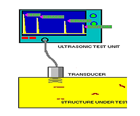
Figure: 8
The ultrasonic tester graphs a peak of energy whenever the transducer receives a reflected wave. As you recall, sound is reflected any time a wave changes mediums. Thus, there will be a peak anytime the waves change mediums. Right when the initial pulse of energy is sent from the tester, some is reflected as the ultrasonic waves go from the transducer into the couplant. The first peak is therefore said to record the energy of the initial pulse. The next peak in a material with no defects is the back wall peak. This is the reflection from waves changing between the bottom of the test material and the material behind it, such as air or the table it is on. The back wall peak will not have as much energy as the first pulse, because some of the energy is absorbed by the test object and some into the material behind it.
The amount of distance between peaks on the graph can be used to locate the defects. If the graph has 10 divisions and the test object is 2 inches thick, each division represents 0.2 inches. If a defect peak occurs at the 8th division, we know the defect is located 1.6 (0.2 x 8) inches into the test object.
If the thickness of the object is unknown, it can be calculated using the amount of time it takes for the back wall peak to occur. The thickness of the object is travelled twice in that time, once to the back wall and once returning to the transducer. If we know the speed of our sound, then we can calculate the distance it travelled, which is the thickness of the object times two.
If a defect is present, it will reflect energy sooner also. Another peak would then appear from the defect. Since it reflected energy sooner than the back wall, the defect's energy would be received sooner. This causes the defect peak to appear before the back wall peak. Since some of the energy is absorbed and reflected by the defect, less will reach the back wall. Thus the peak of the back wall will be lower than had there been no defect interrupting the sound wave.
When the wave returns to the transducer, some of its energy bounces back into the test object and heads towards the back wall again. This second reflection will produce peaks similar to the first set of back wall peaks. Some of the energy, however, has been lost, so the height of all the peaks will be lower. These reflections, called multiples, will continue until all the sound energy has been absorbed or lost through transmission across the interfaces.