Unit-1
DC Circuits
Resistor
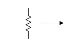
Control the flow of current
V=IR
P=I2R
Behaviour of Resistance:-
t=0- t=0 t=0+ t=∞
R R R R
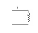
Inductor
- Active - FET, diode
- Passive - R, L, C
Storage of energy
Based on electromagnetic induction
Faraday’s Law
Φ∝i
Φ = L.i


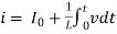
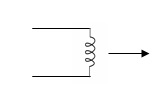
Relaxed inductor I0 = 0

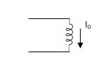
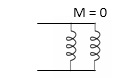
Current Carrying Inductor:

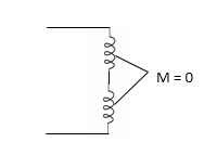
L = L1+L2
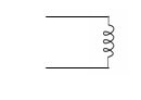

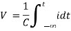
Capacitor:
Charge storing device (voltage)
Q ∝ V
Q = C V


Relaxed capacitor 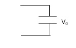
charged capacitor
Electrostatic Energy

Inductor do not respond any change as far as current is concerned.
Capacitor does not respond any change as far as voltage is concerned.
Definition of Open circuit and short circuit
R=∞
V=0 or V≠ 0
I=0
Short Circuit:
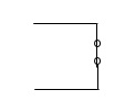
V = 0
R = 0
I may or may not be zero
Categories of sources
- Voltage source and current source
- A.C. Source and D.C. Source
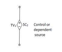
- Dependent source and independent source
- Constant and function of time source
few either
AC or DC 
dc

Equivalent circuit diagram of
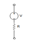
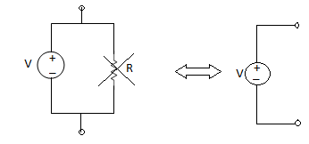
- Voltage Source: A voltage source always have a resistance in series.
Ideal source
R = 0
Practical = 2 - 5Ω
I = 0
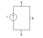
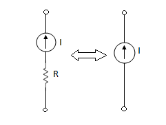
2. Current Source: Always have R parallel with the source.
Ideal and Practical Sources (Independent Sources only)
Ideal and practical Voltage and Current source:
A voltage source is a device which provides a constant voltage to load at any instance of time and is independent of the current drawn from it. This type of source is known as an ideal voltage source. Practically, the ideal voltage source cannot be made. It has zero internal resistance. It is denoted by this symbol.
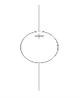
Fig: Voltage source symbol
Ideal Voltage Source
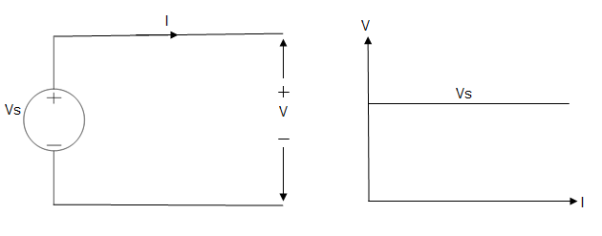
Fig: Ideal Voltage Source
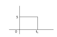
The graph represents the change in voltage of the voltage source with respect to time. It is constant at any instance of time.
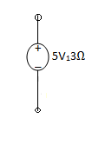
Voltage sources that have some amount of internal resistance are known as a practical voltage source. Due to this internal resistance, voltage drop takes place. If the internal resistance is high, less voltage will be provided to load and if the internal resistance is less, the voltage source will be closer to an ideal voltage source. A practical voltage source is thus denoted by a resistance in series which represents the internal resistance of source.
Practical Voltage source

Fig: Practical Voltage source
The graph represents the voltage of the voltage source with respect to time. It is not constant but it keeps on decreasing as the time passes.
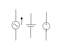
Current source
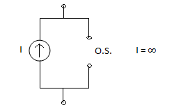
A current source is a device which provides the constant current to load at any time and is independent of the voltage supplied to the circuit. This type of current is known as an ideal current source; practically ideal current source is also not available. It has infinite resistance. It is denoted by this symbol.
Ideal Current source
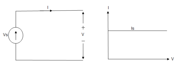
Fig: Ideal Current source
The graph represents the change in current of the current source with respect to time. It is constant at any instance of time.
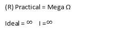
Why ideal Current source has infinite resistance?
A current source is used to power a load, so that load will turn on. We try to supply 100% of the power to load. For that, we connect some resistance to transfer 100% of power to load because the current always takes the path of least resistance. So, in order for current to go to the path of least resistance, we must connect resistance higher than load. This is why we have the ideal current source to have infinite internal resistance. This infinite resistance will not affect voltage sources in the circuit.
Practical Current source
Practically current sources do not have infinite resistance across there but they have a finite internal resistance. So the current delivered by the practical current source is not constant and it is also dependent somewhat on the voltage across it.
A practical current source is represented as an ideal current source connected with resistance in parallel.
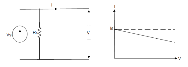
Fig; Practical Current source
The graph represents the current of the current source with respect to time. It is not constant but it also keeps on decreasing as the time passes.
The algebraic sum of currents meeting at a junction or node in a electric circuit is zero or the summation of all incoming current is always equal to summation of all outgoing current in an electrical network.
Explanation
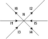
Assuming the incoming current to be positive and outgoing current negative we have


Ie incoming current = ∑ outgoing current thus, the above Law can also be stated as the sum of current flowing towards any junction in an electric circuit is equal to the sum of currents flowing away from that junction
Kirchhoff’s Voltage Law (KVL)
Statement : the algebraic summation of all Voltage in any closed circuit or mesh of loop zero.
Ie ∑ Voltage in closed loop = 0 the summation of the Voltage rise (voltage sources) is equal to summation of the voltage drops around a closed loop in 0 circuit for explanation from here
Determination of sigh and direction of currents (Don’t write in exams just for understanding)
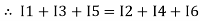
Current entering a resistor is +ve and leaving should be –ve
Now
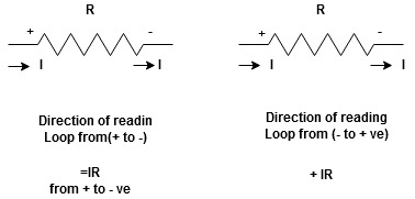


Potential Rise Potential Drop
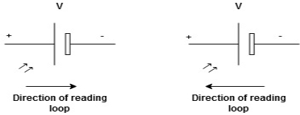
We are reading from +V to –V we are reading from –V to +V
 potential drops
  potential rise
 -V
-V  +V
+V
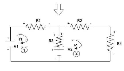
Given Circuit
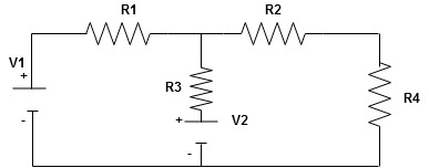
First identify no of loops and assign direction of current flowing in loop
Note : no of loops in circuit = No, of unknown currents = no, of equations in the circuit
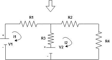
Note : keep loop direction and current direction same ie either clockwise or anticlockwise for all loops I1 I2
Now according to direction of direction assign signs (+ve to –ve) to the resistors
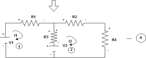
Note : voltage sources (V) polarities does not change is constant.
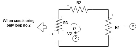
Note: for common resistor between 2 loops appearing in the circuit like R3 give signs according to separate loops as shown
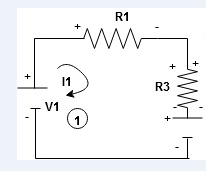
When considering only loop no 1 (+ R3 - )
- B
Now consider diagram A and write equations
Two loops  two unknown currents
  two equation
Apply KVL for loop ① [B. Diagram ]
(+ to drop -) = - sign and (- to rise +) = + sign
 for drop = -sign
 for rise = + sign
-
-( ) R2 is considered because in R3,2 currents are flowing
  and
and  and we have taken (
 ) because we are considering loop no 1 and current flowing is
  in loop no 1
 )
)
Similarly for loop no. 2 currents flowing is  resistor R3 it should be
  )R3
)R3
Consider loop no. 1 apply KVL
- …….①
…….①
-
Consider loop no. 2 apply KVL
- …….②
…….②
-
After solving equation ① and ② we will get branch current  and
and 
And Norton Theorems.
Superposition Theorem:
- This is only applicable to circuits with linear elements.
- If two or more than two independent sources (voltage or current) are operating in the circuit than voltage across any element or current through any element is sum of current and voltages due to individual sources.
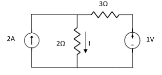
Question 1. Find the current through  resistance.
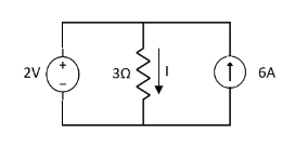
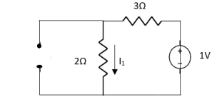
Solution:
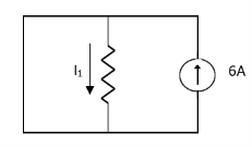
 1= 0
1= 0
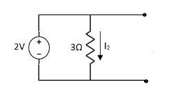
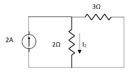
 2=
2=
 1 +
1 +  2
2 
Special Case:
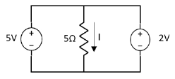
Since two voltage sources with different magnitude in parallel which cannot be connected as in single branch two different current is not possible (if 5V than I = zero).
Question:
 1 =
1 = 
 2 =
2 = 
=
 1 +
1 +  2
2
= 
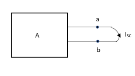
Thevenin’s And Norton’s Theorem
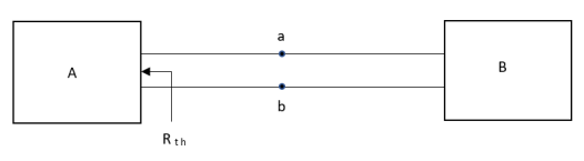
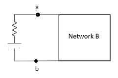
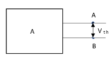
Thevenin’s equivalent of A
Norton’s equivalent of A
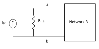
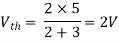
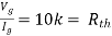
 sc = Vth/Rth
- Norton’s equivalent is obtained by source conversion of thevenin’s equivalent circuit.
CONDITIONS FOR APPLICATION
- For network A:
- Network A should contain linear elements.
- Network A can have independent and dependent current and voltage source.
- If network A has dependent source than controlling parameter must lie in network A itself.
- Network A should not have any source coupling and magnetic coupling.
- For network B:
- It can have linear and non linear elements.
- It can have dependent and independent voltage and current sources.
- It should not have any source and magnetic coupling with network A.
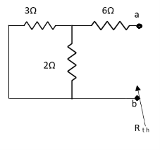
Method for finding Rth :
Firstly, open circuit terminal A and B.
- If network is operating with only independent sources:
- Make all sources zero in network A.
- Find out the equivalent resistance across terminal A and B.
2. If network A is operating with independent and dependent sources:
- Make all independent sources zero in network A.
- Connect a generation between A and B.
3. If network is operating with only dependent sources:
Connect generation between A and B

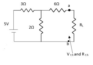
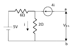
Method for Vth:
First open circuit terminal A and B.
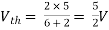
Find out the voltage between A and B this is Vth
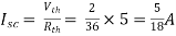
Method for Isc:
- Isc =

- Remove network B and S.C. The terminal A and B and current from terminal A to B Isc.
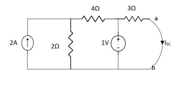
Question:
Answer:


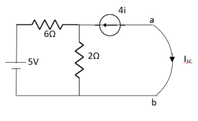
Finding Isc from circuit directly:
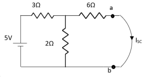
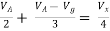
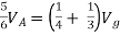
By KCL,
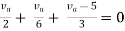


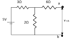
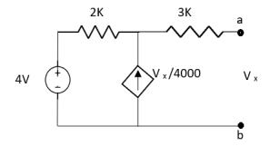
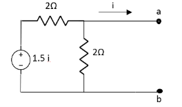
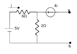
Question:
Answer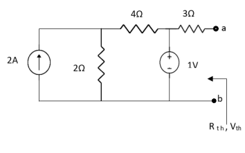
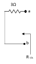
Also, clear from circuit that Vth = 1V.
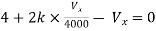
By applying KVL we get,
1-3Isc=0
Isc= A
A
Que:
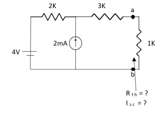
Ans;
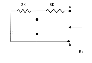
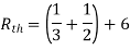
Rth=3k+2k=5k
By applying KVL we get


Therefore, 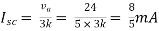
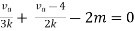
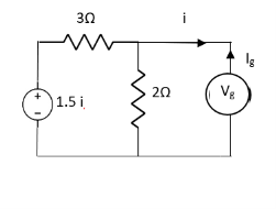
Question:
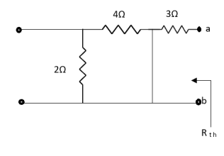
Solution: For Rth
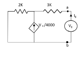
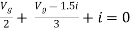
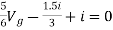
By KCL,
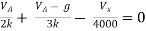

But, 


By KVL,


Question:
Solution: Since, no independent source is present so,
Isc = 0
And we know that,


Since Rth cannot be zero

But 


Question: Find out the Norton’s equivalent
Solution:

Since, there is no significance of current source


FOR RL Circuit
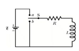
Fig: Series RL circuit
After switch is closed applying KVL
 =0
=0
This is first order homogeneous differential equation so
 dt
dt
Integrating both sides
Ln i=  t+K
t+K
Taking antilog of both sides
i=k
At t=0
i(0)= =I0
=I0
 =ke0
=ke0
The particular solution is given as
i=  for t≥0
= for t<0
FOR RC Circuit
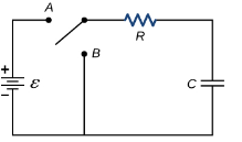
Fig: Series RC circuit
 =V
=V
For t>0 applying KVL
Ri(t)+ +V=0
+V=0

Hence general solution of above equation is calculated same as for RL circuit
i=k
i(0)=- 
Hence, particular solution for network is given as
i=-  for tfor t≥0
= for t<0
Time Constant
Time constant for RL circuit
From above section for RL circuit at t≥0
i= 
i=I0
I0= 
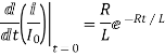
Time taken for current to drop from unity to zero is called as time constant T.

 sec
sec
FOR RC Circuit
It can be calculated in the same manner as for series RL circuit
The time constant is given as 
T=RC
Reference
1 D.P Kothari and I.J Nagrath “Basic electrical engineering” Tata Mcgraw Hill,2010
2 D.C.KulshtreshthaBasic electrical engineering” Tata Mcgraw Hill,2009
3 E.Hughes “Electrical and Electronics Technology” Pearson,2010
4 V.D.Toro “Electrical Engineering Fundamentals” Prentice Hall India, 1989


