Unit-2
AC Circuits
Average Value:
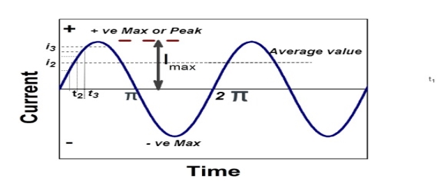
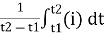
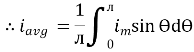
The arithmetic mean of all the value over complete one cycle is called as average value
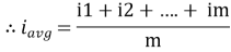
 =
= 
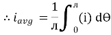
For the derivation we are considering only hall cycle.
Thus  varies from 0 to ᴫ
i = Im Sin
Solving
We get

Similarly, Vavg=
The average value of sinusoid ally varying alternating current is 0.636 times maximum value of alternating current.
RMS value: Root mean square value
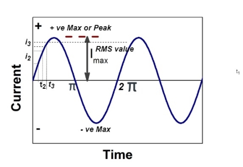
The RMS value of AC current is equal to the steady state DC current that required to produce the same amount of heat produced by ac current provided that resistance and time for which these currents flows are identical.
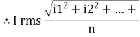
I rms = 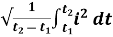
Direction for RMS value:
Instantaneous current equation is given by
i = Im Sin 
But 
I rms = 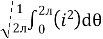
= 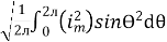
=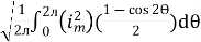
=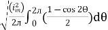
Solving
=
=
Similar we can derive
V rms=  or 0.707 Vm
 the RMS value of sinusoidally alternating current is 0.707 times the maximum value of alternating current.
Real Power: [P]
It is nothing but the actual power being used in a circuit.
P= = I2R Watts
Reactive Power: [Q]
It is the function of reactance in the circuit X. Mainly reactive loads are inductor and capacitors. These elements dissipate zero power. These element shows that they dissipate power. This is called as reactive power.
Q= = I2X VAR (volt-Ampere-Reactive)
Apparent Power: [S]
It is the product of a circuit voltage and current without reference to phase angle. It is the combination of both reactive and real power.
S= = I2Z VA (volt-Ampere)
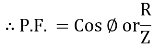
Power factor (P.F.)
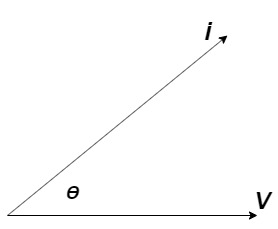
It is the cosine of angle between voltage and current
If Ɵis –ve or lagging (I lags V) then lagging P.F.
If Ɵ is +ve or leading (I leads V) then leading P.F.
If Ɵ is 0 or in phase (I and V in phase) then unity P.F.
Reactance
- Inductive Reactance (XL)
It is opposition to the flow of an AC current offered by inductor.
XL = ω L But ω = 2 ᴫ F
 XL = 2 ᴫ F L
It is measured in ohm
 XL∝FInductor blocks AC supply and passes dc supply zero
2. Capacitive Reactance (Xc)
It is opposition to the flow of ac current offered by capacitor
Xc = 
Measured in ohm
 Capacitor offers infinite opposition to dc supply
Impedance (Z)
The ac circuit is to always pure R pure L and pure C it well attains the combination of these elements. “The combination of R1 XL and XC is defined and called as impedance represented as
Z = R +i X
Ø = 0
 only magnitude
R = Resistance, i = denoted complex variable, X =Reactance XL or Xc
Polar Form
Z =  L I
L I
Where  =
=
 Measured in ohm
Ac circuit containing pure resisting
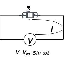
Consider Circuit Consisting pure resistance connected across ac voltage source
V = Vm Sin ωt ①
According to ohm’s law i =  =
= 
But Im = 
 ②
②
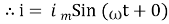
Phases diagram
From ① and ② phase or represents RMD value.
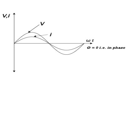
Power P = V. i
Equation P = Vm sin ω t Im sin ω t
P = Vm Im Sin2 ω t
P =  -
- 

Constant fluctuating power if we integrate it becomes zero

Average power
Pavg = 
Pavg = 
Pavg = Vrms Irms
Series RLC circuit
The voltage across inductor = jIXL
Voltage across capacitance = -jIXC
Net voltage across L and C = jI(XL-XC) = j(EL-EC)
Voltage drop across R= IR=ER
Applied voltage E= IR+jI(XL-XC)
E=I
Z=R+j(XL+XC)
Z= 
Φ= tan-1
I= 
CosΦ= R/Z
Active Power= EI CosΦ
Reactive Power = EI SinΦs
Definition: it is defined as the phenomenon which takes place in the series or parallel R-L-C circuit which leads to unity power factor
Voltage and current in R – L - C ckt. Are in phase with each other
Resonance is used in many communicate circuit such as radio receiver.
Resonance in series RLC series resonance in parallel RLC anti resonance / parallel resonance.
- Condition for resonance XL = XC
- Resonant frequency (Fr): for given values of R-L-C the inductive reactance XL become exactly aqual to the capacitive reactance Xc only at one particular frequency. This frequency is called as resonant frequency and denoted by (fr)
- Expression for resonant frequency(fr): we know thet XL = 2ƛ FL - Inductive reactance
Xc =  - capacitive reactance
At a particular frequency ȴ = fr, the Inductive and capacitive reactance are exactly equal
 XL = XC ……at ȴ = fr
Ie  L =
L = 
 fr2 =
fr2 = 
 fr =
fr =  H2
H2
And  = wr =
  rad/sec
Quality factor / Q factor
The quality of resonance circuit is measured in terms of efficiency of L and C to stare energy and the efficiency of L and C to store energy as measured in terms of a factor called quality factor or Q factor it is expressed as
Q =  and Q =
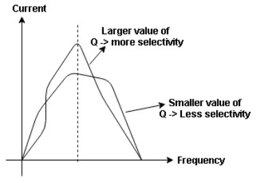
The sharpness of tuning of R-L-C series circuit or its selectivity is measured by value of Q. As the value of Q increases, sharpness of the curve also increases and the selectivity increases.
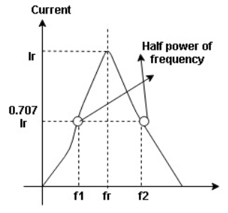
Bandwidth (BW) = f2 = b1
 and
and  are the frequency at which the power delivered to the resistor is reduced to 50% of the power delivered to it at resonance
  these frequency are called as half power frequency
Bw = fr/Q
Resonance in Parallel circuit:
When a coil is in parallel with a capacitor, as shown below. The circuit is said to be in resonance.
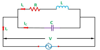
The resonant frequency for above circuit is fr =  Hz
Hz
The current at resonance is I=
The value L/RC is known as dynamic impedance.
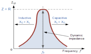
The current at resonance is minimum. The circuits admittance must be at its minimum and one of the characteristics of a parallel resonance circuit is that admittance is very low limiting the circuits current. Unlike the series resonance circuit, the resistor in a parallel resonance circuit has a damping effect on the circuit band width making the circuit less selective.
Also, since the circuit current is constant for any value of impedance, Z, the voltage across a parallel resonance circuit will have the same shape as the total impedance and for a parallel circuit the voltage waveform is generally taken from across the capacitor.
Bandwidth and selectivity:
 and
and  are the frequency at which the power delivered to the resistor is reduced to 50% of the power delivered to it at resonance
  thesefrequency are called as half power frequency
Bw = fr/Q
Q =  =
=  fCR = R
Resonant Frequency:
The resonant frequency for parallel resonant circuit is given as
fR= 
Where L= inductance of the coil
C = is the capacitance
Rs = Resistive value of coil.
Que) A coil takes a current of 6A when connected to 24V dc supply. To obtain the same current with 50HZ ac, the voltage required was 30V. Calculate inductance and p.f of coil?
Sol: The coil will offer only resistance to dc voltage and impedance to ac voltage
R =24/6 = 4ohm
Z= 30/6 = 5ohm
XL = 
= 3ohm
Cosφ =  = 4/5 = 0.8 lagging
Que) The potential difference measured across a coil is 4.5V,when it carries a dc current of 8A. The same coil when carries ac current of 8A at 25Hz,the potential difference is 24V. Find current and power when supplied by 50V,50Hz supply?
Sol: R=V/I= 4.5/8 = 0.56ohm
At 25Hz, Z= V/I=24/8 =3ohms
XL = 
= 2.93ohm
XL = 2 fL = 2
 x 25x L = 2.93
L=0.0187ohm
At 50Hz
XL = 2x3 =6ohm
Z =  = 5.97ohm
I= 50/5.97 = 8.37A
Power = I2R = 39.28W
Que) A coil having inductance of 50mH an resistance 10ohmis connected in series with a 25 F capacitor across a 200V ac supply. Calculate resonant frequency and current flowing at resonance?
Sol: f0= = 142.3Hz
I0 = V/R = 200/10 = 20A
Que) A 15mH inductor is in series with a parallel combination of 80ohm resistor and 20 F capacitor. If the angular frequency of the applied voltage is 1000rad/s find admittance?
Sol: XL = 2 fL = 1000x15x10-3 = 15ohm
XL = 1/ C = 50ohm
Impedance of parallel combination Z = 80||-j50 = 22.5-j36
Total impedance = j15+22.5-j36 = 22.5-j21
Admittance Y= 1/Z = 0.023-j0.022 siemens
Que) A circuit connected to a 100V, 50 Hz supply takes 0.8A at a p.f of 0.3 lagging. Calculate the resistance and inductance of the circuit when connected in series and parallel?
Sol: For series Z =100/0.8 = 125ohm
Cosφ = 
R = 0.3 x 125 = 37.5ohm
XL =  = 119.2ohm
XL = 2 fL = 2
 x 50x L
119.2 = 2 x 50x L
L= 0.38H
For parallel:
Active component of current = 0.8 cosφ = 0.3x0.3 = 0.24A
R = 100/0.24 =416.7ohm
Quadrature component of current = 0.8 sinφ = 0.763
XL= 100/0.763 = 131.06ohm
L= 100/0.763x2 x50 = 0.417H
In three phase the windings are separated by 1200 each. The voltage produced in those windings is 1200 apart from each other. Below shown is one coil RR’ and two more coils YY’ and BB’ each having phase shift of 1200.
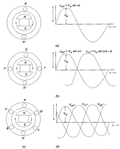
The instantaneous value of voltages is given as
VRR’ = Vmsinωt
VYY’ = Vmsin(ωt-120)
VBB’ = Vmsin(ωt-240)
The three phase voltages are of same magnitude and frequency.
Phase sequence
The change in voltage is in orderVRR’- VYY’- VBB’. So, the three-phase are changed in that order and are called as phase change.
VRR’ = Vmsinωt
VYY’ = Vmsin(ωt-120)
VBB’ = Vmsin(ωt-240)
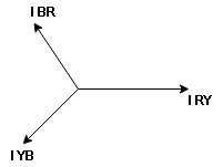
- Phasor Diagram
Consider equation ①
Note : we are getting resultant line current IR by subtracting 2 phase currents IRY and IBR  take phase currents at reference as shown
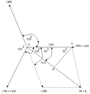
Cos 300 = 
 =
= 
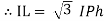
- Complete phases diagram for delta connected balanced Inductive load.
Phase current IYB lags behind VYB which is phase voltage as the load is inductive
- Power relation for delta load star power consumed per phase
PPh = VPh IPh Cos Ø
For 3 Ø total power is
PT= 3 VPh IPh Cos Ø …….①
For star
VL and IL = IPh (replace in ①)
 PT = 3
  IL Cos Ø
 PT = 3
  VL IL Cos Ø – watts
For delta
VL = VPh and IL =  (replace in ①)
PT = 3VL
= 3VL  Cos Ø
Cos Ø
 PT
PT VL IL Cos Ø – watts
Total average power
P =  VL IL Cos Ø – for ʎ and
  load
load
K (watts)
Total reactive power
Q =  VL IL Sin Ø – for star
  delta load
K (VAR)
Total Apparent power
S =  VL IL – for star
  delta load
K (VA)
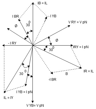
Star Connection:
In this type similar ends are connected to common point called as neutral and having a star shape. These connections are used in case of unbalanced current flowing in the three-phase. To avoid any kind of damage we use this connection.
Line voltage VL = Vphase
Line current IL = Iphase
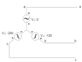
Delta Connection:
There are three wires with no neutral. They are used for short distance due to unbalanced current in circuit.
Line voltage VL =Vphase
Line current IL =  Iphase
Q) Three similar resistors are connected in star across 400V 3-phase lines. Line current is 4A. Calculate the value of each resistor.
Sol: For star connection:
IL=Iph=4A
Vph=VL/ = 400/
 = 231V
Rph= 231/4= 57.75ohm
For Delta Connection:
IL=4A
Iph= IL/
=4/ ==2.30A
Zph=400/2.30=173.9ohm
Rph= 173.9/3 = 57.97ohm
Q) Three identical impedances are connected in delta 3-phase supply of 400V. The line current is 30A and total power taken from the supply is 10kW. Calculate the resistance and reactance value of each impedance?
Sol: VL=Vph=400V
IL=30A
Iph=IL/ = 30/
= 30/ =17.32A
Zph=Vph/Iph= 400/17.32=23.09ohm
P= VLILCos Ø
Cos Ø = 10000/ 400x30 = 0.48
Sin Ø =0.88
Rph=ZphCos Ø= 23.09x0.48=11.08ohm
Xph=ZphSin Ø = 23.09x0.88=20.32ohm
Q) A star connected alternator supplies a delta connected load. The impedance of the load branch is 6+j5 ohm/phase. The line voltage is 230V. Determine the current in the load branch and power consumed by the load.
Sol: Zph= = 7.8ohm
VL=Vph=230V
Iph=Vph/Zph=230/7.8=29.49A
Iph=IL/
IL= Iph=
Iph= x29.49=51.07A
P= VLIL Cos Ø =
  x 230x51.07x0.768=15.62kW
Q) The load connected to a 3-phase supply comprise three similar coils connected in star. The line currents are 25A and the kVA and kW inputs are 18 and 10 respectively. Find the line and phase voltage, the kVAR input resistance and reactance of each coil?
Sol: IL= 25A
P= 10000W
Cos Ø = 10/18 = 0.56
P= VLIL Cos Ø
10000= x VLx25x0.56
VL =412.39V
Vph=VL/ = 412.39/
 =238.09V
KVAR= = 14.96
Zph=238.09/25=9.52ohm
Rph=Zph Cos Ø= 9.52x0.56=5.33ohm
Xph=Zph Sin Ø = 9.52x0.83=7.88ohm
Q) A balanced delta connected load consisting of three coils draws 8 A at 0.5 p.f from 100V 3-phase ac supply. If the coils are reconnected in star across the same supply. Find the line current and total power consumed?
Sol: For Delta connection:
IL=8 A
A
Iph= IL/ = 8A
= 8A
Vph=100V
Zph=100/8=12.5ohm
Rph=Zph Cos Ø=12.5x0.5 = 6.25ohm
Xph=Zph Sin Ø = 12.5x0.866=10.825ohm
P= VLIL Cos Ø
=  x 100x 8
 x0.5=1200W
For Star Connection:
Vph= VL/ = 100/
 V=57.73V
Zph=100/8=12.5ohm
Iph=57.73/12.5=4.62A
P= VLIL Cos Ø
= x 100x 4.62x0.5
P= 400W
Reference
1 D.P Kothari and I.J Nagrath “Basic electrical engineering” Tata Mcgraw Hill,2010
2 D.C.Kulshtreshtha Basic electrical engineering” Tata Mcgraw Hill,2009
3 E.Hughes “Electrical and Electronics Technology” Pearson,2010
4 V.D.Toro “Electrical Engineering Fundamentals” Prentice Hall India, 1989


