UNIT 3
Moment of Inertia
When a distributed loading whose intensity varies linearly acts perpendicular to an area, the computation of the moment of the loading distribution about an axis involves a quantity called the moment of inertia of the area or simply area moment of inertia.
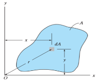
Consider a differential plate, subjected to fluid pressure P that varies linearly with depth, as shown in fig, such that  , where,
  is the specific weight of fluid.
The force acting on a acting on the differential area of the plate is given by

The moment of this this force about the x-axis is

Integrating  over the entire area of the plate yields


The integral part of the moment equation is called area moment of inertia about x-axis 

Similarly, area moment of inertia about y-axis is given as,

Moment of Inertia for area can also be given as

Where, A is the total area
And k is referred as radius of gyration
Radius of gyration for area of a plate about an axis is defined as the radial distance to a point which would have a same moment of inertia as the plate’s actual distribution of area, if the total area of the plate were concentrated.
It is given by,

Moment Of Inertia Of Cylinder
The moment of inertia of cylinder about a perpendicular axis passing through its centre is determined by;
Ix = ¼ MR2 + 1/12 ML2
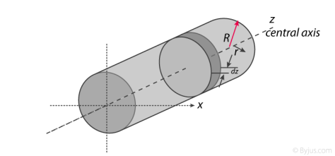
We will look at the derivation of this formula below.
Generally, the derivation involves 3 primary steps. It includes;
- Splitting the cylinder into infinitesimally thin disks and stating the moment of inertia.
- Using both parallel and perpendicular axis theorems to determine the expression.
- Integrating over the length of the cylinder.
1. Cutting the cylinder into infinitesimally thin disks
We will consider the cylinder having mass M, radius R, length L and the z-axis which passes through the central axis.
Here,
Density ρ = M / V
Next, we will consider the moment of inertia of the infinitesimally thin disks with thickness dz.
First, we assume that dm is the mass of each disk, We get;
Dm = ρ X Volume of disk
Dm = M / V X (πr2.dz)
We take V = area of circular face X length which is = πr2L. Now we obtain;
Dm = M / πr2L X (πr2.dz)
Dm = M / L X dz
The moment of inertia about the central axis is given as;
Dlz = ½ dmR2
Use of Perpendicular Axis Theorem
We now apply the perpendicular axis theorem which gives us;
Dlz = dlx + dly
Here, if we need to consider that both x and y moments of inertia are equal by symmetry.
Dlx = dly
We need to combine the equations for the perpendicular axis theorem and symmetry. We get;
Dlx = dlz / 2
Now we substitute lz from the equation above.
Dlx = ½ x ½ dmR2
Dlx = ¼ dmR2
Alternatively, for the x-axis, we use the parallel axis theorem to find the moment of inertia. We get;
Dlx = ¼ dmR2 + dmz2
Integration
Now we conduct integration over the length of the cylinder to express the mass element dm in terms of z. We take the integral from z=0 to z=L.
Ix = o∫L dlx
Ix = o∫L ¼ dzR2 + o∫L ¼ z2 m / l dz
Ix = ¼ M / L R2z + M / L Z3 / 3]0L
Since it is a definite form of integral we ignore the constant. We will now have;
Ix = ¼ M / L R2 L + M / 3L 2L3 / 23
Ix = ¼ MR2 + 1/12 ML2
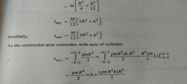
Therefore, I =1/2 MR2
Moment Of Inertia of Sphere
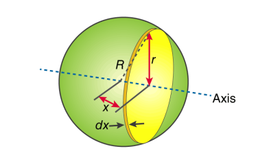
First, we take the moment of inertia of a disc that is thin. It is given as;
I = ½ MR2
In this case, we write it as;
DI (infinitesimally moment of inertia element) = ½ r2dm
Find the dm and dv using;
Dm = p dV
p = moment of a thin disk of mass dm
Dv = expressing mass dm in terms of density and volume
DV = π r2 dx
Now we replace dV into dm. We get;
Dm = p π r2 dx
And finally, we replace dm with dI.
DI = ½ p π r4 dx
The next step involves adding x to the equation. If we look at the diagram we see that r, R and x forms a triangle. Now we will use Pythagoras theorem which gives us;
r2 = R2 – x2
Now if we substitute the values we get;
DI = ½ p π (R2 – x2)2 dx
This leads to:
I = ½ p π -R∫R (R2 – x2)2 dx
After integration and expanding we get;
I = pπ 8/15 R5
Additionally, we have to find the density as well. For that we use;
P (density) = M (mass) / V (volume)
p = M (mass) / (4/3 πR3)
If we substitute all the values;
I = 8/15 π [M / (4/3 πR3)] R5
I = ⅖ MR2
Moment of inertia of Solid Cone
We will take a solid cone where its axis will pass through the centre with radius = r, height = h. We will need to determine the mass though.
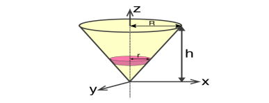
We take the elemental disc whose mass is given by;
Dm = ρ⋅ π r2dz
Density is given as;
ρ = M / V = M / (⅓π R2h)
With this, we will calculate the dm.
Dm = [M / (⅓π R2h)] X π r2dz
Dm = (3M / R2h) Xr2dz
If we consider the similarity of the triangle, then we have;
R / r = h / z
r = R .z / h
Now,
Dm = (3M / R2h )⋅( R2 / h2) ⋅ z2dz
Dm = (3M / h3 ). z2dz
If we consider z-axis, the moment of inertia of the elemental disk will be;
DI = ½ dmr2
DI = ½ ⋅(3M / h3) . z2 ⋅(z2 R2 / h2) dz
DI = 3 / 2 ⋅ M R2 / h5 X z4dz
Now we will follow the integration process. Here;
I = 3 / 2 ⋅ M R2 / h5 o∫h z4dz
I = 3 / 2 ⋅ M R2 / h5 [z5 / 5 ]oh
I = 3 / 2 ⋅ M R2 / h5 ⋅ h5 / 5
Therefore, I = 3/10 MR2
Parallel axes theorem
Parallel axis theorem states that
The moment of inertia of a body about an axis parallel to the body passing through its centre is equal to the sum of moment of inertia of body about the axis passing through the centre and product of mass of the body times the square of distance between the two axes.
Parallel Axis Theorem Formula
Parallel axis theorem statement can be expressed as follows:
I = Ic + Mh2
Where,
- I is the moment of inertia of the body
- Ic is the moment of inertia about the centre
- M is the mass of the body
- h2 is the square of the distance between the two axes
Parallel Axis Theorem Derivation
Let Ic be the moment of inertia of an axis which is passing through the center of mass (AB from the figure) and I be the moment of inertia about the axis A’B’ at a distance of h.
Consider a particle of mass m at a distance r from the center of gravity of the body.
Then,
Distance from A’B’ = r + h
I = ∑m (r + h)2
I = ∑m (r2 + h2 + 2rh)
I = ∑mr2 + ∑mh2 + ∑2rh
I = Ic + h2∑m + 2h∑mr
I = Ic + Mh2 + 0
I = Ic + Mh2
Hence, the above is the formula of parallel axis theorem.
Theorem of perpendicular axes
It states that , if  be the moments of inertia of figure or plane section about two axis x and y which are perpendicular to each other at point O, then moment of Inertia of that plane section about Z axis which is perpendicular to the plane [&(
 is given by :

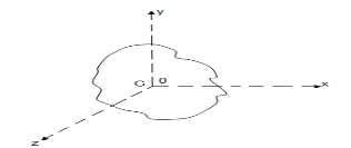
 of plane area aboutZ axis passing through C.G.
 of plane area aboutX axis passing through C.G
 of plane area about Y axis passing through C.G
 Is also called as polar moment of Inertia (J)
The moment of inertia of a body about an axis is sometimes represented using the radius of gyration. Now, what do you mean by the radius of gyration? We can define the radius of gyration as the imaginary distance from the centroid at which the area of cross-section is imagined to be focused at a point in order to obtain the same moment of inertia. It is denoted by k.
Radius of Gyration Formula
The formula of moment inertia in terms of the radius of gyration is given as follows:
I = mk2 (1)
Where I is the moment of inertia and m is the mass of the body
Accordingly, the radius of gyration is given as follows
k=√I/m (2)
The unit of the radius of gyration is mm. By knowing the radius of gyration, one can find the moment of inertia of any complex body equation (1) without any hassle.
Consider a body having n number of particles each having a mass of m. Let the perpendicular distance from the axis of rotation be given by r1, r2, r3,…,rn. We know that the moment of inertia in terms of radius of gyration is given by the equation (1). Substituting the values in the equation, we get the moment of inertia of the body as follows

………… (3)
If all the particles have the same mass then equation (3) becomes

We can write mn as M which signifies the total mass of the body. Now the equation becomes

………… (4)
From equation (4), we get
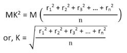
From the above equation, we can infer that the radius of gyration can also be defined as the root-mean-square distance of various particles of the body from the axis of rotation.
What is the use of radius of gyration?
The radius of gyration is used to compare how various structural shapes will behave under compression along an axis. It is used to predict buckling in a compression beam or member.
Polar Moment of Inertia is a measure of an object’s capacity to oppose or resist torsion when some amount of torque is applied to it on a specified axis. Torsion, on the other hand, is nothing but the twisting of an object due to an applied torque. Polar moment of inertia basically describes the cylindrical object’s (including its segments) resistance to torsional deformation when torque is applied in a plane that is parallel to the cross-section area or in a plane that is perpendicular to the object’s central axis.
If we put it in simple terms polar moment of inertia is the resistance offered by a beam or shaft when it is being distorted by torsion. This opposition usually arises from the cross-sectional area and it should be noted that it does not depend on the material composition. If the polar moment of inertia is of higher magnitude then the torsional resistance of the object will also be greater. More torque will be required to turn the shaft at an angle.
Nonetheless, it is one of the main aspects of the area moment of inertia and we can use the perpendicular axis theorem to link the two quantities.
Polar Moment Of Inertia Formula
Polar Moment of Inertia is also called the second polar moment of area. It is usually denoted by IZ. However, sometimes J or JZ is also used. Polar Moment of Inertia can be represented mathematically with the given formula;
I or J = r2 dA
Here,
r = distance to the element dA.
Units
The dimension unit of polar moment of inertia is length to the power of four (L4); The SI unit of this property is, meters to the fourth power (m4). In the imperial unit system, it is inches to the fourth power (in4).
Types of Cross-section Polar Moment of Inertia
There are three main types of cross-section polar moment of inertia. They are as follows.

1. Hollow Shaft
To determine the polar moment of inertia we use;
Jhollow = π(R04–R14)/2
R1 and Ro = inner and outer radius of the hollow shaft.
2. Thin-Walled Shaft
To determine the polar moment of inertia we use;
Jthin = 2πt [R0+Ri/2]3
t = thickness of the thin-walled shaft.
3. Solid Circular Shaft
To determine the polar moment of inertia we use the following formula;
Jsolid = πR4/2
R = radius of the circular shaft.
Uses and Limitations
Generally, the second polar moment of area is used in determining the angular displacement of a body that is subjected to torque or to calculate the torsion force on a circular body. As for the limitation, the polar moment of inertia is not suitable for analysing shafts and beams with non-circular cross-sections. This is mainly because objects with non-circular cross-sections tend to warp when torque is applied and it further leads to out-of-plane deformations.
The area product of inertia is defined as
The x and y terms inside the integral denote the centroidal position of the differential area measured from the y and x axes, respectively. Similar to moments of inertia discussed previously, the value of product of inertia depends on the position and orientation of selected axes. It is possible for the product of inertia to have a positive, negative, or even a zero value.
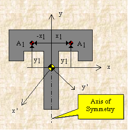
If, for example, either x or y represents an axis of symmetry, then the product of inertia Ixy would be zero. To see why this is the case, take a look at the figure to the right. Consider the small area A1 to the right of y axis at the distance of x1. Then consider a similar area to the left of this axis of symmetry at the distance of -x1. Since both areas are at the same vertical position from the x-axis, they have the same value of y. The contribution from the left area is -x1yA1 and that from the right is x1yA1 which add up to zero. Since every point on one side of the axis of symmetry has an equal counterpart on the other side, the total value of the integral would be zero.
However, if we were to consider the product of inertia with respect to the x' and y' axes, then Ix'y' would not be zero. We will have more discussion about the product of inertia in the section on principal axes.
For a general three-dimensional body, it is always possible to find 3 mutually orthogonal axis (an x, y, z coordinate system) for which the products of inertia are zero, and the inertia matrix takes a diagonal form. In most problems, this would be the preferred system in which to formulate a problem. For a rotation about only one of these axis, the angular momentum vector is parallel to the angular velocity vector. For symmetric bodies, it may be obvious which axis is principle axis. However, for an irregular-shaped body this coordinate system may be difficult to determine by inspection; we will present a general method to determine these axes in the next section. But, if the body has symmetries with respect to some of the axis, then some of the products of inertia become zero and we can identify the principal axes.
For instance, if the body is symmetric with respect to the plane  then, we will have
  and
and  will be a principal axis. This can be shown by looking at the definition of the products of inertia.
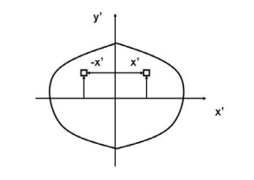
The integral for, say,  can be decomposed into two integrals for the two halves of the body at either side of the plane
  . The integrand on one half
  will be equal in magnitude and opposite in sign to the integrand on the other half (because
  will change sign). Therefore, the integrals over the two halves will cancel each other and the product of inertia
  will be zero. (As will the product of inertia
  ) Also, if the body is symmetric with respect to two planes passing through the center of mass which are orthogonal to the coordinate axis, then the tensor of inertia is diagonal, with
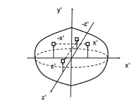
Another case of practical importance is when we consider axisymmetric bodies of revolution. In this case, if one of the axis coincides with the axis of symmetry, the tensor of inertia has a simple diagonal form. For an axisymmetric body, the moments of inertia about the two axis in the plane will be equal. Therefore, the moment about any axis in this plane is equal to one of these. And therefore, any axis in the plane is a principal axis. One can extend this to show that if the moment of inertia is equal about two axis in the plane (IP P = Ixx), whether or not they are orthogonal, then all axes in the plane are principal axes and the moment of inertia is the same about all of them. In its inertial properties, the body behaves like a circular cylinder.
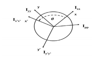
The tensor of inertia will take different forms when expressed in different axes. When the axes are such that the tensor of inertia is diagonal, then these axes are called the principal axes of inertia.
The Search for Principal Axes and Moments of Inertia as an Eigenvalue Problem
Three orthogonal principal axes of inertia always exist even though in bodies without symmetries their directions may not be obvious. To find the principle axis of a general body consider the body shown in the figure that rotates about an unknown principal axis. The total angular momentum vector is  in the direction of the principle axis. For rotation about the principal axis, the angular momentum and the angular velocity are in the same direction.
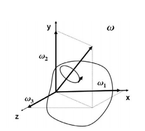
We seek a coordinate axes x, y and z, about which a rotation ωx, ωy and ωz, which is aligned with this coordinate direction, will be parallel to the angular momentum vector and related by the equation

We then express the general form for angular momentum vector in components along the x, y and z axis in term of the components of ω along these axes using the general form of the inertia tensor in the x, y, z system, we have

At this point in the process we know the inertia tensor in an arbitrary x, y, and z system and are seeking the special orientation of ω which will align the angular momentum HG with the angular velocity ω. Collecting terms from equation(11) on the left-hand side, we obtain

The structure of the solution for finding the principal axes of inertia and their magnitudes is a characteristicvalue problem. The three eigenvalues give the directions of the three principal axis, and the three eigenvectors give the moments of inertia with respect to each of these axis. In principal directions, the inertia tensor has the form

A rigid body is an idealization of a solid body where the deformations occurring on the body are neglected. In other words, the distance between any two given points of a rigid body remains a constant regardless of the external force acting upon it.
The concept of rigid body and Rigid body dynamics was developed to solve a range of problems that could not be explained with classical physics. Motions such as rotation of a fan, a potter’s wheel, a top, etc cannot be adequately explained with a point mass. In real life, in the case of bodies such as wheels and steel rods, deformation or bending is considered to be negligible, and we treat them as rigid.
Rigid Body Dynamics:
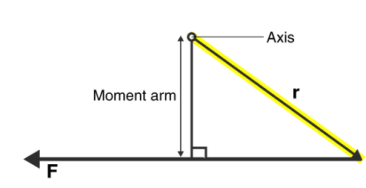
The question is, what kind of motion can a rigid body have? This new outlook meant that there now could be two different types of rigid body motion. We could explore and understand more kinds of problems and in doing so develop a deeper understanding of the world around us. Rigid Body Dynamics laid the foundation to what has come after, Quantum Mechanics. The two types of motion a rigid body can undergo are;
- Translational Motion
- Rotational Motion
Configuration Space for a Rigid Body:
A macroscopic body is made up of a very large number of atoms. Describing the motion of such a system without some simplifications is clearly impossible. Many objects of interest, however, are very well approximated by the assumption that the distances between the atoms in the body are fixed. This constitutes a set of holonomic constraints, but not independent ones, as we have here 12n(n−1) constraints on 3n coordinates.
Rather than trying to solve the constraints, we can understand what are the generalized coordinates by recognizing that the possible motions which leave the interparticle lengths fixed are combinations of translations of the body as a whole, r⃗ α→r⃗ α+C⃗ and rotations of the body about some fixed, or “marked”, point.
We will need to discuss how to represent the latter part of the configuration, (including what a rotation is), and how to re-express the kinetic and potential energies in terms of this configuration space and its velocities.
The first part of the configuration, describing the translation, can be specified by giving the coordinates of the marked point fixed in the body, R~(t). Often, but not always, we will choose this marked point to be the center of mass R⃗ (t) of the body.
In order to discuss other points that are part of the body, we will use an orthonormal coordinate system fixed in the body, known as the body coordinates, with the origin at the fixed point R.The constraints mean that the position of each particle of the body has fixed coordinates in terms of this coordinate system. Thus, the dynamical configuration of the body is completely specified by giving the orientation of these coordinate axes in addition to R~. This orientation needs to be described relative to a fixed inertial coordinate system, or inertial coordinates, with an orthonormal basis ei.
Stay tuned with BYJU’S to learn more about Rigid Body Dynamics, Translational Motion and Rotational Motion, and much more with interesting video lectures.
Velocity
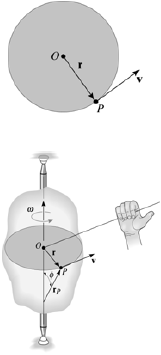
The magnitude of the velocity of P is equal to ωr (the text provides the derivation). The velocity’s direction is tangent to the circular path of P. In the vector formulation, the magnitude and direction of v can be determined from the cross product of ωand rp .Here rp is a vector from any point on the axis of rotation to P.
v= ωx rp = ωx r
The direction of v is determined by the right-hand rule.
In above figure ∆ = displacement vector
∆r = displacement of particle (magnitude).
∆t = time taken by particle to move from P to P’.
Avg. Velocity =  = vavg.
When the time interval approaches to zero∆t → 0.
Instantaneous velocity at P will be,
V = 
V = 
Speed = 
Acceleration
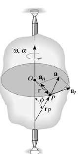
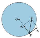
The acceleration of P is expressed in terms of its normal (an) and tangential (at) components.
In scalar form, these are at = αr and an = ω2 r. The tangential component, at, represents the time rate of change in the velocity's magnitude. It is directed tangent to the path of motion.
The normal component, an, represents the time rate of change in the velocity’s direction. It is directed toward the center of the circular path.
Using the vector formulation, the acceleration of P can also be defined by differentiating thevelocity.
a = dv/dt = dω/dt x rP + ωx drP/dt
= αx rP + ωx (ωx rP)
It can be shown that this equation reduces to
a = αx r – ω2r = at + an
The magnitude of the acceleration vector is a = √((at)2 + (an)2)
Avg. Acceleration a = 
For very small interval of time ∆t → 0
Thus a =  &
&
The acceleration at point P = 
(Instantaneous acceleration)
Relative velocity is used to denotethe aircraft moving in the wind or boats movingthroughthe water,etc. The velocity is measured within the object according to theobserver. It can be measured using the use of an intermediate reference frame.
In simpler terms, this can be the vector sum of the velocities. The relative velocity formula is expressed as

Where
VAB is the velocity with respect to A and B, VBC is the velocity with respect to B and C and VAC is the velocity with respect to A and C.
The velocity of an object A relative to another object B is the velocity that objects A would appear to have to an observer moving with B.
Have you ever been sat in a stationary train at a station, and seen another train moving off forwards? Did you feel you were moving backwards even though you knew you were stationary?
To you, sitting on the stationary train (A), or to a person on the platform, the moving train (B) appears to be travelling at a velocity v away. However, to a person on the moving train the platform and the stationary train at the platform both appear to be moving in the opposite direction with the same speed, or to put it another way, with the opposite velocity. Really what we are measuring in all of these cases is the velocity relative to an observer.
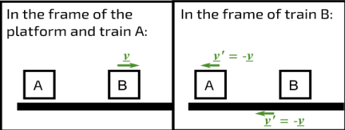
Figure 1: Relative velocities of trains A and B and the platform
A rigid body is an ideal body that does not change its shape when subjected to external forces or couples. The distance between the particles in a rigid body remains same during the motion. Hence, a rigid body can be defined as the group or collection of number of particles at fixed distance from each other.
There are three types of motion of a rigid body
- Translation
- Rotation
- General Plane Motion
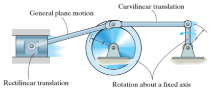
Kinematics of rigid body in translation motion
Translation motion occurs when a line (generally axis) in the body remains parallel to its initial orientation throughout the motion.
If the path of motion of any two lines on the rigid body is parallel or is in a straight line, then the translation is termed as rectilinear translation.
If the path of motion of any two lines on the rigid body is along the fixed curve, then the translation is termed as curvilinear translation.
Consider a rigid body that is subjected to translation motion as shown in fig.
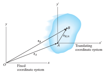
The position of points A and B is defined are defined by the position vectors  and
and  w.r.t the fixed frame x, y.
Let the translating system is fixed in a body with origin A which is referred to the base point. The position vector of B w.r.t A is denoted by  .
.
By vector addition, we get,


Taking, the first time derivative of the above equation, we get,

According to the definition of rigid body, the term  is constant
Hence,

And,  gives the absolute velocities
  and
and  respectively with respect to the fixed frame.
So, we get,

This shows that, for the rigid body in translation motion, the velocity of every particle on the body is same.
Now, taking the time derivative of the velocity equation, it simply yields

Where,  and
and  are the absolute accelerations of points A and B on the rigid body w.r.t fixed frame.
This shows that, for the rigid body in translation motion, the velocity and acceleration of every particle on the body is same.
Kinematics of a body rotating about fixed axis
When a rigid body is subjected to the rotation about a fixed axis, as shown in fig below, all the particles of the body, except those which lie on the axis of rotation, move along circular paths whose center lies on the axis of rotation.
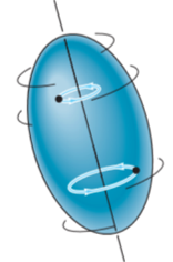
Consider the point P on the rigid body defined by the position vector r. As the rigid body rotates about the fixed axis, then the point P travels a circular path of radius r with center point O as shown in fig below
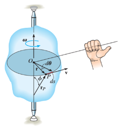
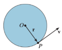
If the body rotates with a differential angular displacement , then the point P displaces the distance
  , which is given by

Differentiating the above equation w.r.t time, we get

The term,  is referred to as the angular velocity
  of the rotating body
And  gives the velocity of point P
Hence,

The direction of velocity is tangent to the circular path.
Considering the magnitude and direction, velocity is the cross product of angular velocity and the position vector

Where,  is directed from axis to the point P
To find acceleration, differentiate velocity vector w.r.t time

Here, the term  refers to the angular acceleration
  of the rigid body
And  is the velocity
Hence,


Where,  is the tangential acceleration and
  is normal component of acceleration
Hence,

Magnitude of both components is given by,


Tangential component refers to the time rate of change of velocity’s magnitude. Hence, if velocity of point P is increasing,  is in same direction of
  , but if velocity of point P is decreasing,
  is in direction opposite to that of
The normal component of acceleration refers to time rate of change of the velocity’s direction. Hence, the direction of the normal component is always from point P towards the center O. Hence it is also called as centripetal acceleration.
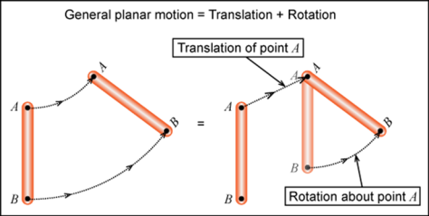
General plane motion of a rigid body refers to a combination of translation and rotation motion.
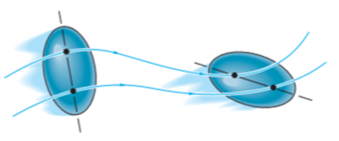
General planar motion refers to the simultaneous rotational and translational motion of a planar body in a 2-D plane.
General planar motion can be fully specified by knowing both the angular rotation of a line fixed in the body and the motion of any point on the body.
These motions can be related by using a rectilinear position coordinate s to locate the point along its path and an angular position coordinate  to specify the orientation of the line. Then these two coordinates are related using the geometry of the problem. The following relation is found.

Differentiating the above equation, gives the relation between velocity  and angular velocity
  .
.
Where,

Then again differentiating, it yields to the relation between acceleration  and angular acceleration
Where,


