UNIT 2
POLARIZATION
There is more to be said about the complex vector amplitudes Ɛ and B. We introduce a right-handed set of orthogonal unit vectors (Ɛ1, Ɛ2, n), as shown in Figure, where we take n to be the propagation direction of the plane wave. In general, the electric field amplitude Ɛ can be written as
 …………(1)
Where the amplitudes and are arbitrary complex numbers. The two plane waves
 …………(2)
And
 …………(3)
If the n index of refraction is real, Ɛ and B have the same phase) are said to be linearly polarized with polarization vectors Ɛ1 and Ɛ2 .Thus the most general homogeneous plane wave propagating in the direction k=kn is expressed as the superposition of two independent plane waves of linear polarization:
 …………(4)
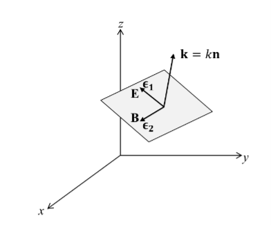
Figure 1
It is convenient to express the complex components in polar form. Let
 …………(5)
Then, for example,
 …………(6)
That is  1 is the phase of the E-field component in the Ɛ1-direction. It is no restriction to let
 2
2 1
1  1=0 …………(7)
Since  1=0 merely dictates a certain choice of the origin of t. With this choice,
 …………(8)
Or the real part is
 …………(9)
The E -field is resolved into components in two directions, with real amplitudes a1 and a2, which may have any values. In addition the two components may be oscillating out of phase by  , that is, at any given point x, the maximum of E in the Ɛ1-direction may be attained at a different time from the maximum E of in the –direction Ɛ2.
A detailed picture of the oscillating E-field at a certain point, e.g. x=0, is best seen by considering some special cases.
 …………(10)
Linearly polarized wave
If E1 and E2 have the same phase  , i.e.,
 …………(11)
Represents a linearly polarized wave, with its polarization vector
Ɛ = Ɛ1cosθ + Ɛ2sinθ …………(12)
With θ=tan-1 (a2/a1) and a magnitude E= as shown in Figure.
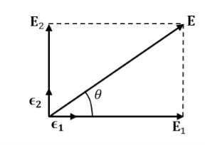
Figure 2: field of a linearly polarized wave
If a1 =0 or a2=0, we also have linear polarization. For ,
,
 …………(13)
Is again linearly polarized.
Elliptically polarized wave
If E1 and E2 have different phases, the wave of equation 8 is elliptically polarized. The simplest case is circular polarization. Then a1 = a2 and  :
:
 …………(14)
At a fixed point in space, the fields are such that the electric vector is constant in magnitude, but sweeps around in a circle at a frequency ω, as shown in Figure
For  +=
+=  , the tip of the E-vector traces the circular path counter clockwise. This wave is called left circularly polarized (positive helicity) in optics.
For  ,
, ), same path but traced clockwise, then the wave is called right circularly polarized (negative helicity). For other values of
  , we have elliptical polarization for the trace being an ellipse.
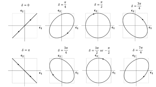
Figure 3: Trace of the tip of the E-vector (a1 = a2) at a given point in space as a function of time. The propagation direction is point toward us. The traces for  and
and  are linearly polarized. The traces for
  and
and  are left and right circularly polarized, respectively.
When electromagnetic wave travels in space, it carries energy and energy density is always associated with electric fields and magnetic fields.
The rate of energy travelled through per unit area i.e. the amount of energy flowing through per unit area in the perpendicular direction to the incident energy per unit time is called Poynting vector.
Mathematically Poynting vector is represented as
 =
=  =(
=(  ) (i)
) (i)
The direction of Poynting vector is perpendicular to the plane containing  and
and  . Poynting vector is also called as instantaneous energy flux density. Here rate of energy transfer
  is perpendicular to both
  and
and . It represents the rate of energy transfer per unit area.
UNIT
Its unit is W/m2.
Poynting Theorem
Poynting theorem states that the net power flowing out of a given volume V is equal to the time rate of decrease of stored electromagnetic energy in that volume decreased by the conduction losses.
i.e. total power leaving the volume =Rate of decrease of stored electromagnetic energy – ohmic power dissipated due to motion of charge
Proof
The energy density carried by the electromagnetic wave can be calculated using Maxwell's equations
Div  = 0 ...(i)
Div  =0 ...(ii)
Curl  = -
= -  …(iii)
Curl  =
=  +
+  …(iv)
…(iv)
Taking scalar product of (3) with H and (4) with 
i.e.  curl
curl  = -
= - 
 ……(v)
……(v)
And  curl
curl  =
=  +
+  .
.  …..(vi)
Doing (vi) – (v) i.e.


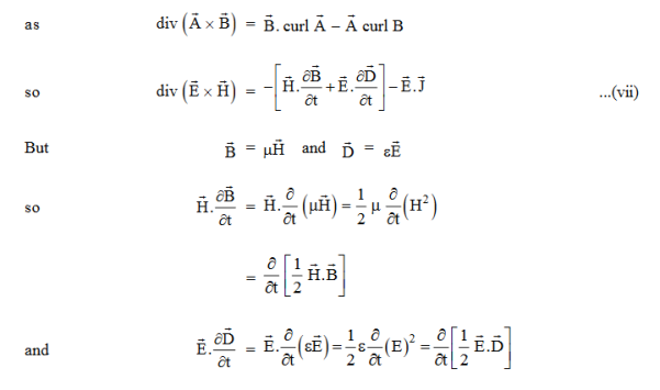
So, from equation (vii)

Or

Integrating equation (viii) over a volume V enclosed by a Surface S

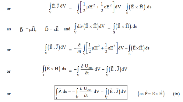
Total power leaving the volume = rate of decrease of stored e.m. Energy -ohmic power dissipated due to charge motion
This equation (ix) represents the Poynting theorem according to which the net power flowing out of a given volume is equal to the rate of decrease of stored electromagnetic energy in that volume minus the conduction losses.
In equation (ix)  .ds represents the amount of electromagnetic energy crossing the closed surface per second or the rate of flow of outward energy through the surface S enclosing volume V i.e. it is Poynting vector.
The term represents

The energy stored in electric and magnetic fields respectively and their sum denotes the total energy stored in electromagnetic field. So total terms gives the rate of decrease of energy stored in volume V due to electric and magnetic fields.

Gives the rate of energy transferred into the electromagnetic field.
This is also known as work-energy theorem. This is also called as the energy conservation law in electromagnetism.
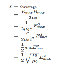
The intensity of the radiation is the magnitude of the average value of the Poynting vector.
Note: Poynting vector  is also represented by
  in most of the books. Don’t get confused.
We know that in classical physics a particle is well localized in space. We can calculate its position and velocity simultaneously.
But for quantum mechanics, a particle is not well localized in space. We cannot calculate its position and velocity simultaneously.
In Quantum mechanics it is describe that the matter wave associated with the particle. Wave functions depend on the whole space. Hence, they cannot be localized.
If the wave function is made to vanish everywhere except in the neighbourhood of the particle or the neighbourhood of the classical trajectory, it can then be used to describe the dynamics of the particle. That is a particle which is localized within a certain region of space can be described by a matter wave whose amplitude is large in that region and zero outside it. This matter wave must then be localized around the region of space within which the particle is confined.
A localized wave function is called a Wave Packet or Wave Group. A wave packet or wave group therefore consists of a group of waves of slightly different wavelengths with phases and amplitudes so chosen that they interfere constructively over a small region of space and destructively elsewhere.
Wave packets are Not only useful in the explanation of isolated particles that are confined to a certain spatial region but they also play a key role in understanding the connection between quantum mechanics and classical mechanics. The wave packet concept also represents a uniting mathematical tool that describes particle-like behaviour and also its wave-like behaviour.
Phase and group velocity are two important and related concepts in wave mechanics. They arise in quantum mechanics in the time development of the state function for the continuous case, i.e. wave packets.
According to the theory of relativity particle velocity (v) is always less than the speed of light c. But according to the De-Broglie wave velocity must be greater than c. This is an unexpected result. According to this the de-Broglie wave associated with the particle would travel faster than the particle itself thus leaving the particle far behind.
The difficulty was recovered by Schrodinger. He proposed that a material particle in motion is equivalent to a wave packet rather than a single wave. Wave packet comprises of a group of waves, each with slightly different velocity and wavelength.
The function
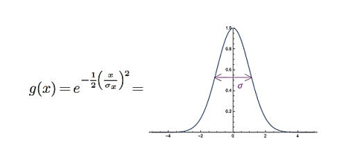
Figure 4
Is called a Gaussian. For a Gaussian, note that
g(±σx) =  g(0)≈0.6g(0), so when x=±σx, the Gaussian has decreased to about 0.6 of its value at the top. Alternatively, the Gaussian is at half its maximal value at x=±1.1σx. Either way, σx indicates the width of the Gaussian. The plot above has σx= 1.
You may recall that the power of a driven oscillator is given by a Lorentzian function l(x) =γ/x2+γ2, which has roughly similar shape to a Gaussian and decays to half of its value at the top at x=±γ.
The Fourier transform of the Gaussian is

This is also a Gaussian, but with width σk=1/σx. Thus, the narrower the Gaussian is in position space (σx→0), the broader its Fourier transform is(σk→∞), and vice versa.
When σ=∞, the Gaussian is infinitely wide: it takes the same value at all x. Then g ̃(k) becomes a δ-function at k= 0. That is, to construct a constant, one only needs the infinite wave-length mode (recall λ=2π/k).
To construct something narrower than a constant, one needs more and more wavenumbers. To construct a very sharp Gaussian in x(σx→0) the Fourier transform flattens out: one needs an infinite number of wavenumbers to get infinitely sharp features. As you know, if we shift the Gaussian g(x+x0), then the Fourier transform rotates by a phase. Conversely, if we shift the Fourier transform, the function rotates by a phase. Even with these extra phases, the Fourier transform of a Gaussian is still a Gaussian

The Gaussian is called a wave packet because of its Fourier transform: it is a packet of waves with frequencies/wavenumbers clustered around a single value kc(the subscript “c” is for “carrier”).
Such a wave packet moves with its own velocity vg called the group velocity.
The individual wave forming the wave packet possesses an average velocity vp called the phase velocity.
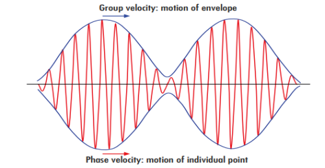
Figure 5
It can be shown that the velocity of the material particle v is the same as group velocity
Let us assume two wave trains have same amplitude but different frequency and phase velocities
u (x, t) =A sin(ωt - kx) …….(1)
u’(x, t) =A sin[(ω+∆ω)t-(k+∆k)x] …….(2)
Where ω and (ω+Δω) are angular frequencies and k and (k +Δk) are propagation constants
The superposition of two waves is of the form
ψ(x,t) = u +u’ = A sin(ωt - kx)sin[(ω+∆ω)t - (k+∆k)x] …….(3)
As Δ ω and Δk are small therefore (ω+Δω)  and (k + Δk)
  k, equation (3) reduces to
ψ(x,t) = 2Acos[  t -
t - x] sin(ωt - kx) .…….(4)
This equation represents a vibration of amplitude
2Acos[  t -
t - x] …….(5)
The phase of the resultant wave moves with the velocity known as phase velocity
vp=  ……..(6)
And the amplitude moves with the velocity known as group velocity
vg = =
= 
vg =  ….….(7)
We’ll now study the reflection and refraction that arise when light propagating in one medium encounters another medium. For example, we might have light traveling through air and then encountering a region of glass. We’ll begin with the case of normal incidence and then eventually get to the more complicated case of non-normal incidence. For the case of normal incidence, we’ll start off by considering only one boundary.
Normal Incidence
We begin with the simplest possible case: a plane wave normally incident on a plane dielectric interface. We will see that the boundary conditions are satisfied only if reflected and transmitted waves are present.
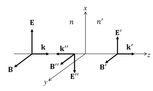
Figure 6: Reflection and transmission at normal incidence
The prime symbol ′, double prime symbol ″, triple prime symbol ‴,
Figure 5 describes the incident wave (E,B) travelling in the z-direction, the reflected wave (E″,B″) travelling in the minus z-direction, and the transmitted wave (E′, B′) travelling in the z-direction. The interface is taken as coincident with the xy-plane at z=0, with two dielectric media with the indices of refraction, n for z and for n z
 . The electric fields, which are assumed to be linearly polarized in the x-direction, are described by
 …………(1)
Where
 …………(2)
And

Therefore, the magnetic fields associated with the electric fields of equation (1) are given by
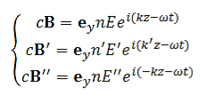 …………(3)
Clearly the reflected and transmitted waves must have the same frequency ω as the incident wave if boundary conditions at z=0 are to be satisfied for all t. The E-field must be continuous at the boundary
E - E″ = E′ …………(4)
The H-field must also be continuous, and for nonmagnetic media ( ), so must be the B-field:
n(E + E″ ) = n′ E′ …………(5)
Equations (3) and (4) can be solved simultaneously for the amplitudes E′ and E″ in terms of the incident amplitude E:
 …………(6)
The Fresnel coefficients for normal incidence reflection and transmission are defined as
 …………(7)
For n′ n, there is a phase reversion for the reflected wave. What is usually measureable is the reflected and transmitted average energy fluxes per unit area i.e. the intensity of EM wave given by the magnitude of the Poynting vector
 …………(8)
We define the reflectance R and the transmittance T for normal incidence by the ratios of the intensities
 …………(9)
With the Fresnel coefficients given by Equation 7, and satisfy
R+T =1 …………(10)
For any pair of non-conducting media. This is an expression of energy conservation at the interface.
Oblique Incidence
We consider reflection and refraction at the boundary of two dielectric media at oblique incidence. The discussion will lead to three well-known optical laws: Snell’s law, the law of reflection, and Brewster’s law governing polarization by reflection.
Figure 7depicts the situation that the wave vectors k, k′ and k″ are coplanar and lie in the xz-plane. The media for z and z
and z have the indices of refraction n, and n′, respectively.
The unit normal to the boundary is n. The plane defined by k and n is called the plane of incidence, and its normal is in the direction of k  n.
n.
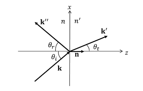
Figure 7: Reflection and transmission at oblique incidence. Incident wave k strikes plane interface between different media, giving rise to a reflected wave k″ and refracted wave k′.
The three plane waves are:
Incident
 …………(11)
Refracted
 …………(12)
Reflected
 …………(13)
Where
 …………(14)
Phase matching on the boundary
Not only must the refracted and reflected waves have the same frequency as the incident wave, but also the phases must match everywhere on the boundary to satisfy boundary conditions at all points on the plane at all times:
 …………(15)
This condition has three interesting consequences. Using the vector identity
 …………(16)
And n.x=0 on the boundary, we obtain
 …………(17)
We substitute this into equation (15)
 …………(18)
And similarly, for the other members of Equation (15). Since is an arbitrary vector on the boundary, Equation (15) can hold if and only if
 …………(19)
This implies that
(i)All three vectors, k, k′ and k″ lie in a plane, i.e., and lie in the plane of incidence;
(ii)Law of reflection:  =
=  =
=  thus
thus  =
= 
(iii)Snell’s Law:  =
=  =
=  thus
thus  =
=  .
.
Boundary conditions and Fresnel coefficients
At all points on the boundary, normal components of D and B and tangential components of E and H are continuous. The boundary conditions at are
 …………(20)
In applying the boundary conditions, it is convenient to consider two separate situations:
The incident plane wave is linearly polarized with its polarization vector
(a) Perpendicular (s-polarization) and
(b) Parallel (p-polarization) to the plane of incidence
(See Figure 8):
For simplicity, we assume the dielectrics are nonmagnetic ( ),
),
(a) s-polarization
The E-fields are normal to n, therefore (i) in Equation (20) is automatically satisfied. (iii) and (iv) give
 …………(21)
 …………(22)
While(ii), using Snell’s law, duplicates (iii). With Equations (21) and (22), we obtain the s-pol Fresnel coefficients,
 …………(23)
..….……(24)
Where, using Snell’s law, we could write
 …………(25)
(b) p-polarization
The B-fields are normal to n, therefore (ii) in Equation (20) is automatically satisfied. (iii) and (iv) give
 …………(26)
And
 …………(27)
While (i), using Snell’s law, duplicates (iv). With Equation (26) and (27), we obtain the p-pol Fresnel coefficients,

..………(28)
And

...….…(29)
For normal incidence, rp = - rs = - ( )/(
)/(  ), because we assign opposite directions for E and E
 for p-polarization.
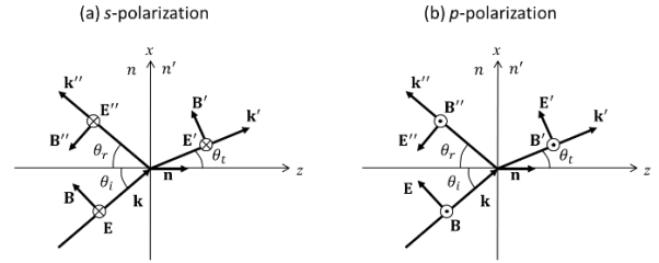
Figure 8: Reflection and refraction with polarization (a) perpendicular (s-polarization) and (b) parallel (p-polarization) to the plane of incidence
For certain purposes, it is more convenient to express the Fresnel coefficients in terms of the incident and refraction angles,  and
and  only. Using the Snell’s law,
 =
=  ,we can write

Then
 ..………(30)
Similarly,
 ..………(31)
 …..……(32)
And
 .………(33)
Polarization at the Brewster angle is a practical means of producing polarized radiation. If a plane wave of mixed polarization is incident on a plane interface at the Brewster angle, the reflected radiation is completely s-polarized. The generally lower reflectance for p-polarized lights accounts for the usefulness of polarized sun glasses. Since most outdoor reflecting surfaces are horizontal, the plane of incidence for most reflected glare reaching the eyes is vertical. The polarized lenses are oriented to eliminate the strongly reflected s-component.
We consider the dependence of R and T on the angle of incidence, using the Fresnel coefficients.
We will start with expression of p-polarized reflected wave

We can see the above equation vanishes when  +
+  =
= . Using Snell’s law, we can determine Brewster’s angle
  =
= at which the p-polarized reflected wave is zero:

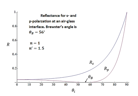
Figure 9: shows Rs and Rp as a function of  with n=1 and
  = 1.5, as for an air-glass interface. The Brewster angle
  is 560 for this case.
Total internal reflection
There is another case in which Rs and Rp equations (24) and (29) indicates that perfect reflection occurs for  =
= . The incident angle for which
  is called the critical angle, From Snell’s law

 can exist only if
  , i.e., the incident and reflected waves are in a medium of larger index of refraction than the refracted wave.
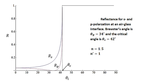
Figure 10
For waves incident at  , the refracted wave is propagated parallel to the surface. There can be no energy flow across the surface. Hence at that angle of incidence there must be total reflection. For incident angles greater than the critical angle
  , Snell’s law gives

This means that  is a complex angle with a purely imaginary cosine.

Then equations (24) and (29) indicates that rs and rp both take the form

Where a and b are real, therefore,

The result is that Rs and Rp is 1 for all . This perfect reflection is called total internal reflection. The meaning of this total internal reflection becomes clear when we consider the propagation factor for the refracted wave

Where

With the wavelength of the radiation λ. This shows that, for  , the refracted wave is propagating only parallel to the surface and is attenuated exponentially beyond the interface. The attenuation occurs within a few wavelengths of the boundary except for
  ,
,
Plane Monochromatic Waves in Conducting Media
In a conducting medium there is an induced current density in response to the -field of the wave. The current density J is linearly proportional to the electric field (Ohm’s law, Eq. 5.21):
J =  …………(1)
The constant of proportionality  is called the conductivity. For an electromagnetic plane wave with direction of propagation (Eq. 7.12) described by
 …………(2)
The Maxwell equation
 …………(3)
Becomes
 …………(4)
Where we define a complex dielectric constant
 …………(5)
Comparing Equation (5) with the following result

We can obtain that the transverse dispersion relation results in
 …………(6)
Where we define a complex refractive index
 …………(7)
To interpret the wave propagation in the conducting medium, it is useful to express the complex propagation vector k as
 …………(8)
Then the plane wave is expressed as
 …………(9)
This is a plane wave propagating in the direction kr with wavelength λ= 2π/ kr; but it decreases in amplitude, most rapidly in the direction ki.
A plasma is very similar to a gaseous medium, expect that the electrons are free: i.e., there is no restoring force due to nearby atomic nuclei.
Expression for the dielectric constant of the collection of atoms is given by
 | …………(10) |
Hence, we can obtain an expression for the dielectric constant of a plasma from equation (10) by setting ω0 to zero, and n to the number density of electrons, ne. We obtain
 | …………..(11) |
Where the characteristic frequency
 | ……………(12) |
is called the plasma frequency. We can immediately see that formula (12) is challenging.
For frequencies above the plasma frequency, the dielectric constant of a plasma is less than unity. Hence, the refractive index n = is also less than unity.
This shows that high frequency electromagnetic waves can propagate through a plasma with a velocity c/n which is greater than the velocity of light in a vacuum.
On the other hand, for frequencies below the plasma frequency, the dielectric constant is negative, which would seem to imply that the refractive index n = is imaginary.
Consider an infinite plane-wave, of frequency, ω, greater than the plasma frequency, propagating through a plasma. Suppose that the wave electric field takes the form
|
Suppose that the wave electric field takes the form
 | ………..(13) |
The physical electric field is the real part of the above expression. A peak of the above wave travels with phase velocity, which is given by
 | ………….(14) |
Now, we have also seen that the phase velocity of electromagnetic waves in a dielectric medium is vp = c/n = c / , so
, so
 | …………..(15) |
It follows from Eq. (11) that
 | ……………(16) |
In a plasma. The above type of expression is called a dispersion relation. This gives relation between the wave frequency, ω, and the wave-number, k.
According to the above dispersion relation, the phase velocity of high frequency waves propagating through a plasma is given by
 | …………(17) |
Which is greater than  .
.
The theory of relativity says is that information cannot travel at a velocity greater than c. And the peaks of an infinite plane-wave, such as (9), do not carry any information.
We now need to consider how we could transmit information through plasma (or any other dielectric medium) by means of electromagnetic waves. The easiest way would be to send a series of short discrete wave-pulses through the plasma, so that we could encode information in a sort of Morse code. We can build up a wave-pulse from a suitable superposition of infinite plane-waves of different frequencies and wave-lengths: e.g.,
 | …………...(18) |
Where
 ,
,
And ω(k) is determined from the dispersion relation (16). Now, it gives that a relatively short wave-pulse can only be built up from a superposition of plane-waves with a relatively wide range of different k values.
Hence, for a short wave-pulse, the integrand in the above formula consists of the product of a fairly slowly varying function, F(k), and a rapidly oscillating function, exp[i ϕ(k)].
The function is rapidly oscillating because the phase ϕ(k) varies very rapidly with k, relative to F(k). We expect the net result of integrating the product of a slowly varying function and rapidly oscillating function to be small, since the oscillations will generally average to zero.
It follows that the integral (18) is dominated by those regions of k-space for which ϕ(k) varies least rapidly with k. Hence, the peak of the wave-pulse most likely corresponds to a maximum or minimum of ϕ(k):
 | …………(19) |
Thus, the velocity of the wave-pulse is given by
 | ……………(20) |
This velocity is called the group velocity, and is different to the phase velocity in dispersive media, for which ω is not directly proportional to k. In a vacuum, ω =kc, and both the phase and group velocities are equal to c.
The outcome of the above discussion is that information travels through a dispersive media at the group velocity, rather than the phase velocity. Hence, relativity demands that the group velocity, rather than the phase velocity, must always be less than c.
Group velocity for high frequency waves propagating through plasma
Differentiation of the dispersion relation (16) yields
 | …………..(21) |
Hence, it follows from equation (17) that
 | ………….(22) |
Which is less than c. We thus conclude that the dispersion relation (16) is indeed consistent with relativity.
Let us now consider the propagation of low frequency electromagnetic waves through plasma. We can see, from Equations. (17) and (22), that when the wave frequency, ω, falls below the plasma frequency, ωp, both the phase and group velocities become imaginary.
This indicates that the wave attenuates as it propagates. Consider, a plane-wave of frequency ω  ωp . According to the dispersion relation (16), the associated wave-number is given by
 | …………..(23) |
Hence, the wave electric field takes the form
 | ……………(24) |
Indeed, it can be seen that for ω  ωp electromagnetic waves in plasma take the form of decaying standing waves, rather than traveling waves.
We conclude that an electromagnetic wave, of frequency less than the plasma frequency, which is incident on a plasma will not propagate through the plasma. Instead, it will be totally reflected.
We can be sure that the incident wave is reflected by the plasma, rather than absorbed, by considering the energy flux of the wave in the plasma. It is easily demonstrated that the energy flux of an electromagnetic wave can be written
 | ……………(25) |
For a wave with a real frequency and a complex  -vector, the above formula generalizes to
 | ……………..(26) |
However, according to equation (23), the k-vector for a low frequency electromagnetic wave in a plasma is purely imaginary. It follows that the associated energy flux is zero. Hence, any low frequency wave which is incident on the plasma must be totally reflected, since if there were any absorption of the wave energy then there would be a net energy flux into the plasma.
The outermost layer of the Earth's atmosphere consists of a partially ionized zone known as the ionosphere. The plasma frequency in the ionosphere is about 1MHz, which lies at the upper end of the medium-wave band of radio frequencies. It follows that low frequency radio signals (i.e., all signals in the long-wave band, and most in the medium-wave band) are reflected off the ionosphere. For this reason, such signals can be detected over the horizon.
Indeed, long-wave radio signals reflect multiple times off the ionosphere, with very little loss and can consequently be detected all over the world.
On the other hand, high frequency radio signals pass straight through the ionosphere. For this reason, such signals cannot be detected over the horizon, which accounts for the relatively local coverage of FM radio stations.
Note, from Eq. (12), that the plasma frequency is proportional to the square root of the number density of free electrons. The level of ionization in the ionosphere is maintained by ultra-violet light from the Sun. Of course, there is no such light at night, and the number density of free electrons in the ionosphere consequently drops as electrons and ions gradually recombine. It follows that the plasma frequency in the ionosphere also drops at night, giving rise to a marked deterioration in the reception of distant medium-wave radio stations.