UNIT 1
Introduction
Force [(F) or ( P )] :-
It is an external agency which produces or tends to produce, destroy or tends to destroy motion.
OR
It is an external agent which changes or tends to change the state of motion of body.
It is a vector quantity.
Force is also known as rate of change of momentum.
As momentum = mass x velocity
But mass will never change, then
Force = mass x rate of change of velocity
= mass x Acceleration
F = P = ma
S.I. Unit: - Newton (N)
KiloNewton (KN) = 103 N
MegaNewton (MN) = 106 N
GigaNewton (GN) = 103 N
TeraNewton (TN) = 1012 N
1 Kg Force:-
Force required to produce unit gravitational acceleration on unit mass.
01 kg force = mass x Accln(gravity)
= 1 kg x 9.81 m / s2
= 9.81 kg.m / s2
1 kg.F = 9.81 Kg m / s2
1 kg.F = 9.81 N
i.e. 1 Kg = 9.81 N
Characteristics of Force:-
1>. Magnitude:- The value of force i.e. 10N, 2KN, etc.
2>. Direction:- Line of action & angle formed with fixed axis.
3>. Nature of force or sense:-It means whether the force is push or pull.


Pull type force Push type force
Push:- Force acting towards the point
Pull: - Force acting away from the point.
4>. Point of application:-
The point at which or through which the force acts.
Effects of Force:-
Force may produce following effects on the body.
1>. It may change the state of body.
i.e. if body is at rest, force may bring it in motion or if body is in motion, force may accelerate it or force may stop it or may retard it.
2>. It may produce internal stress in the body.
3>. It may produce deformation in non-rigid body.
4>. It may produce rotational effect in body.
5>. It may keep the body in stable state (Equilibrium).
When a single agency is acting on body then it is known as force. But when numbers of forces are acting on the body simultaneously, then it is known “System of force”.
Types of Force System
1. Co-planer Forces
2. Non Co-planer Forces
3. Co-linear Forces
4. Non Co-linear Forces
5. Concurrent Forces
6. Non Concurrent Forces
7. Parallel Forces (Like & unlike)
8. Coplanar Concurrent Forces
9. Coplanar Non Concurrent Forces
10. Non Coplanar Concurrent Forces
11. Non Coplanar Non Concurrent Forces
1. Co – planer Force System / Forces:-


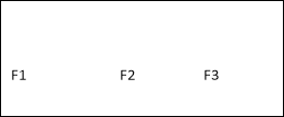 The forces whose line of action lies on the same plane are called as Co-planer Forces.
The forces which are acting in the same plane are known as co-planer forces.
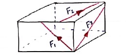
2. Non Co-planer Force System / Forces:-
- A forces whose line of action does not lie in the same plane ( i.e. lie in different planes )
- Forces which are acting in the different planes known as non-co-planer forces (system).
3. Co-linear force system / Forces:-
- The forces whose line of action lies on the same line are called as co-linear forces.
- The forces which are acting along the same straight line are called as co-linear forces.
4. Non – Collinear Forces / force system:-
- The forces which are not acting along the same straight line are known as non-co-linear forces.
- The forces whose line of action doesn’t lie on the same line.
F2


 F1
F1


 F1 F3 F2
5. Concurrent forces / Force system:-
- The forces whose line of action meets at one common point are called concurrent forces.
- The forces which are passing through a common point are concurrent forces.
- The forces which meets at one point are concurrent forces.
6. Non Concurrent force system / forces:-
- The forces which are not passing through common point OR
- The forces whose line of action does not meet at common point OR
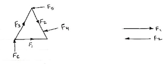 - The force which does not meet at one point is called as non-concurrent forces.
7. Parallel Forces / Force system:-
The forces whose lines of actions are parallel to each other are called as parallel forces.
a) Like parallel Forces:-
The forces whose lines of actions are parallel to each other and having same direction are called like parallel forces.
Forces which are parallel to each other & acting in same direction are called as Like parallel forces.


F1 F2 F3
b. Unlike parallel Forces:-
The forces which are parallel to each other but having different directions orThe forces which are parallel to each other & acting in opposite direction are called as unlike parallel forces.


F1 F2 F3 F4 F5
8. Coplanar concurrent forces:-
The forces which meets at one point & their lines of action also lie on the same plane are called as coplanar concurrent force system.

 F5 F4
F5 F4


 F1
F1
F2 F3
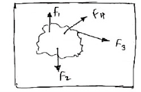
9. Coplanarnon-concurrent forces:-
The forces which do not meet at one point but their line of action lies on the same plane are known as coplanar non-concurrent system of force.

10. Non Coplanar concurrent forces:-
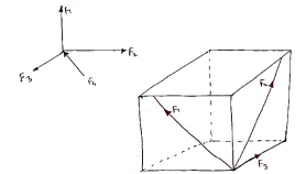 The forces which meets at one point but their line of action do not lie on the same plane are known as non-coplanar concurrent forces.
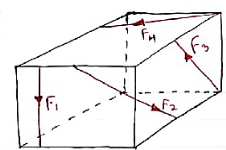
11. Non coplanar non-concurrent forces:-
Their forces which do not meet at one point & their lines of actions do not lie on the same plane are called as non - coplanar non-concurrent forces.
Newton’s law
Law I
Each body remains in its state of rest or motion uniform in direction until it is made to change this state by imposed forces.
Law II
The change of motion is proportional to the imposed driving force and occurs along a straight line in which the force acts.
Law III
To every action there is always an equal reaction: or the mutual interactions of two bodies are always equal but directed contrary.
Scalars
A physical quantity which is completely described by a single real number is called a
Scalar. Physically, it is something which has a magnitude, and is completely described
By this magnitude. Examples are temperature,densityand mass. In the following,
Lowercase (usually Greek) letters, e.g.
,,
, will be used to represent scalars
Scalars
A physical quantity which is completely described by a single real number is called a scalar. Physically, it is something which has a magnitude, and is completely described by this magnitude. Examples are temperature, density and mass. In the following lowercase (usually Greek) letters, e.g. will be used to represent scalars
Vectors
The concept of the vector is used to describe physical quantities which have both a
Magnitude and a direction associated with them. Examples are force, velocity,
Displacement and acceleration.
Geometrically, a vector is represented by an arrow; the arrow defines the direction of the
Vector and the magnitude of the vector is represented by the length of the arrow, Fig.
1.1.1a.
Analytically, vectors will be represented by lowercase bold-face Latin letters, e.g. a, r, q.
The magnitude (or length) of a vector is denoted by
a
Ora. It is a scalar and must be
Non-negative. Any vector whose length is 1 is called a unit vector; unit vectors will
Usually be denoted by e
Vectors
The concept of the vector is used to describe physical quantities which have both a magnitude and a direction associated with them. Examples are force, velocity, displacement and acceleration. Geometrically, a vector is represented by an arrow; the arrow defines the direction of the vector and the magnitude of the vector is represented by the length of the arrow, Fig 1a. Analytically, vectors will be represented by lowercase bold-face Latin letters, e.g. a, r, q. The magnitude (or length) of a vector is denoted by lal or a. It is a scalar and must be non-negative. Any vector whose length is 1 is called a unit vector; unit vectors will usually be denoted by e

Vector Algebra
The operations of addition, subtraction and multiplication familiar in the algebra of
Numbers (or scalars) can be extended to an algebra of vectors.
Vector Algebra
The operations of addition, subtraction and multiplication familiar in the algebra of numbers (or scalars) can be extended to an algebra of vectors.
Vector addition
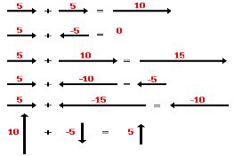
A variety of mathematical operations can be performed with and upon vectors. One such operation is the addition of vectors. Two vectors can be added together to determine the result (or resultant). This process of adding two or more vectors has already been discussed in an earlier unit. Recall in our discussion of Newton's laws of motion, that the net force experienced by an object was determined by computing the vector sum of all the individual forces acting upon that object. That is the net force was the result (or resultant) of adding up all the force vectors. During that unit, the rules for summing vectors (such as force vectors) were kept relatively simple. Observe the following summations of two force vectors:
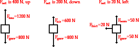
These rules for summing vectors were applied to free-body diagrams in order to determine the net force (i.e., the vector sum of all the individual forces). Sample applications are shown in the diagram below
In this unit, the task of summing vectors will be extended to more complicated cases in which the vectors are directed in directions other than purely vertical and horizontal directions. For example, a vector directed up and to the right will be added to a vector directed up and to the left.
Vector subtraction is a straightforward extension of vector addition. To define subtraction (say we want to subtract B from A , written A – B , we must first define what we mean by subtraction. The negative of a vector B is defined to be –B; that is, graphically the negative of any vector has the same magnitude but the opposite direction, as shown in Figure 1. In other words, B has the same length as –B, but points in the opposite direction. Essentially, we just flip the vector so it points in the opposite direction.
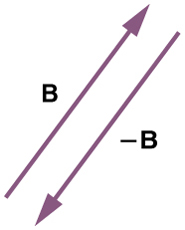
Figure 1The negative of a vector is just another vector of the same magnitude but pointing in the opposite direction. So B is the negative of –B; it has the same length but opposite direction.
The subtraction of vector B from vector A is then simply defined to be the addition of –B to A. Note that vector subtraction is the addition of a negative vector. The order of subtraction does not affect the results.
A – B = A + (-B)
This is analogous to the subtraction of scalars (where, for example, 5 – 2 = 5 + (–2)). Again, the result is independent of the order in which the subtraction is made.
The Dot Product
The dot product of two vectors a and b (also called the scalar product) is denoted by a.b It is a scalar defined by

here is the angle between the vectors when their initial points coincide and is restricted to the range 
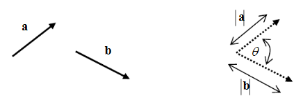
An important property of the dot product is that if for two (proper) vectors a and b, the
Relation
0ba
, then a andb are perpendicular. The two vectors are said to be
Orthogonal.
An important property of the dot product is that if for two (proper) vectors a and b, the relation a.b=0 then a and b are perpendicular. The two vectors are said to be orthogonal.
Also,
)0cos(aaaa
, so that the length of a vector is
Also,  so that the length of a vector is
Another important property is that the projection of a vector u along the direction of a
Unit vector e is given by
Eu
. This can be interpreted geometrically as in Fig. 1.1.5
Another important property is that the projection of a vector u along the direction of a unit vector e is given by u.e. This can be interpreted geometrically as in
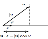
The projection of a vector along the direction of a unit vector
The Cross Product
The cross product of two vectors a and b (also called the vector product) is denoted by
Ba
. It is a vector with magnitude
The Cross Product
The cross product of two vectors a and b (also called the vector product) is denoted by a x b It is a vector with magnitude

With
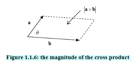
Defined as for the dot product. It can be seen from the figure that the magnitude
Of
Ba
Is equivalent to the area of the parallelogram determined by the two vectors a
Andb.
With defined as for the dot product. It can be seen from the figure that the magnitude of a x b is equivalent to the area of the parallelogram determined by the two vectors a and b.
Section 1.1
Solid Mechanics Part III Kelly
6
Figure 1.1.5: the projection of a vector along the direction of a unit vector
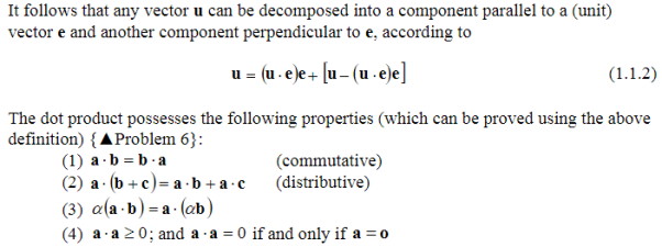
It follows that any vector u can be decomposed into a component parallel to a (unit)
Vectore and another component perpendicular to e, according to
Eeuueeuu
(1.1.2)
The dot product possesses the following properties (which can be proved using the above
Definition) {▲Problem 6}:
(1)
Abba
(commutative)
(2)
Cabacba
(distributive)
(3)
Baba
(4)
0aa
; and
0aa
If and only if
Oa
1.1.5 The Cross Product
The cross product of two vectors a and b (also called the vector product) is denoted by
Ba
. It is a vector with magnitude
Sinbaba
(1.1.3)
With
Defined as for the dot product. It can be seen from the figure that the magnitude
Of
Ba
Is equivalent to the area of the parallelogram determined by the two vectors a
Andb.
Figure 1.1.6: the magnitude of the cross product
The direction of this new vector is perpendicular to both a andb. Whether
Ba
Points
“up” or “down” is determined from the fact that the three vectors a, b and
Ba
Form a
Right handed system. This means that if the thumb of the right hand is pointed in the
The direction of this new vector is perpendicular to both a andb. Whether
Ba
Points
“up” or “down” is determined from the fact that the three vectors a, b and
Ba
Form a
Right handed system. This means that if the thumb of the right hand is pointed in the
The direction of this new vector is perpendicular to both a and b. Whether
A x b points “up” or “down” is determined from the fact that the three vectors a, b and a x b form a right handed system. This means that if the thumb of the right hand is pointed in thedirection of a x b and the open hand is directed in the direction of a, then the curling ofthe fingers of the right hand so that it closes should move the fingers through the angle  bringing them to b. Some examples are shown in Fig. 1.1.7.
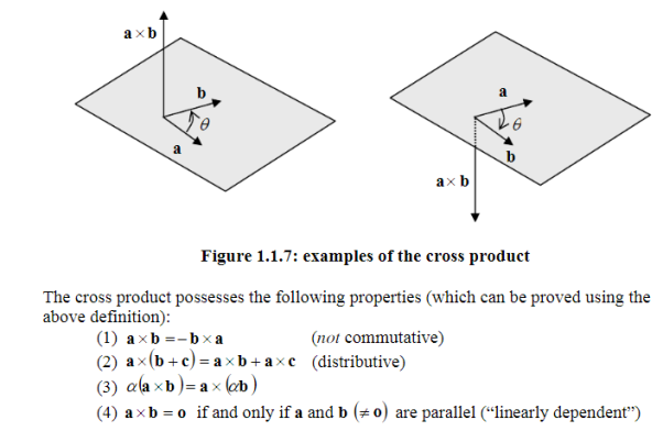
Direction of
Ba
, and the open hand is directed in the direction of a, then the curling of
The fingers of the right hand so that it closes should move the fingers through the angle
,
0
, bringing them to b. Some examples are shown in Fig. 1.1.7, and the open hand is directed in the direction of a, then the curling o bringing them to b. Some examples are shown in Fig. 1.1.7
The Dot Product
The dot product of two vectors a and b (also called the scalar product) is denoted by
Ba
. It is a scalar defined by
Cosbaba
. (1.1.1)
Here is the angle between the vectors when their initial points coincide and is restricted
To the range
0
, Fig. 1.1.4
Moment:-
The turning effect produced by a force on the body on which it acts is called as Moment.
Moment of force about any point is the product of magnitude of force and perpendicular distance of force from the point about which moment is to be taken.
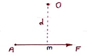
Let force F is applied at point A as shown & O is any point about which we want to take moment.
Thus from point O, draw OM line perpendicular to the line of action of force.
OM = d = Perpendicular distance between Force & point O.
Moment = M = F x d
Graphical representation of Moment:-
- Select suitable scale to locate the force graphically.
- Draw a line parallel to line of action of force. Length of this line can be calculated from selected scale.
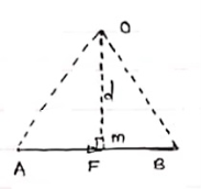 - Length of a line will be equal to magnitude of force.In the figure, Force F is represented by line AB.
- Now let O is the moment center&
OM = d = perpendicular distance
By definition, Mo = F xd
Now join OA & OB, then
In Δ OAB
Area (ΔOAB) = ½ x AB x OM
2 (Area of ΔOAB) = F xd = Mo
Thus the moment of any force about any point is numerically equal to twice area of triangle in which base represents force & height represents the perpendicular distance.
A pair of two equal and opposite (unlike) parallel forces (of same magnitude) is known as couple.
Properties of Couple:-
1>. Two unlike parallel, non-collinear forces of same magnitude will form couple.
2>. Resultant of couple is always zero.
3>. Moment of couple is product of one of the force & lever arm of couple.
M = F xd
Lever arm of couple = ḻlar distance betn couple forces.
4>. Couple cannot be balanced by single force.
5>. Couple can be balanced only by another couple of opposite nature.
6>. Moment of couple is independent of moment centre. i.e. Ref. Point is not required to take moment of couple.
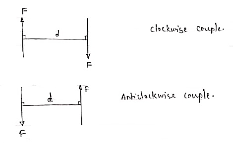
The moment of a couple is the product of the magnitude of one of the forces and the perpendicular distance between their lines of action. M = F x d. It has the units of kip-feet, pound-inches, KN-meter, etc. The magnitude of the moment of a couple is the same for all points in the plane of the couple. A couple may be moved anywhere in its plane or a parallel plane without changing its external effect. The magnitude of the couple is independent of the reference point and its tendency to create a rotation will remain constant. This can be illustrated with the simple illustration of a bar with a length d that is pinned at its midpoint. Two parallel forces of equal magnitude, opposite in sense are applied at the ends of the bar. The magnitude of the moment generated by the couple of the forces F, relative to the pin in the illustration, is equal to
(F)(d/2) + (F)(d/2)
= (F)(d)
The magnitude of the couple of the forces F relative to point "O" is
(F)(d+x) - (F)(x)
(F)(d) + (F)(x) - (F)(x)
= (F)(d)
Again, it can be seen that the magnitude of the couple is independent of the reference location. It is always equal to (F)(d)!
The resultant of a number of couples is their algebraic sum. A couple CANNOT be put in equilibrium by a single force! A couple can only be put in equilibrium by a moment or another couple of equal magnitude and opposite direction anywhere in the same plane or in a parallel plane. If a single force is added to the system that balances the sum of the moments, one of the other two equations of equilibrium will not be satisfied. A couple maintains the internal equilibrium of a simple beam or of many other simple structural systems. The concept is very important to the further study of structural behaviour.
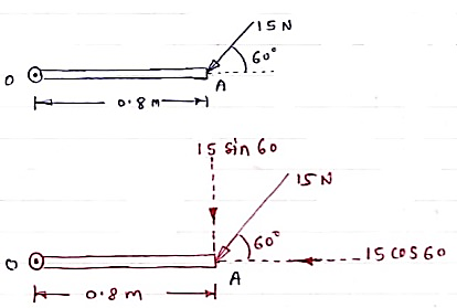 Question )A force of 15 N is applied at an angle of 600 to the edge of door as shown in figure. Find the moment of this force.
Solution:-
Resolving force at point B & then taking the moment about point O,
M0 = (15 Cos 60 x 0) + (15 Sin 60 x 0.8)
 = 0 + 10.39
M0 = 10.39 N.m
A 90 N force is applied to the control rod AB. Determine moment of this Force about point B.
Solution:-
As we don’t know perpendicular distance betn force & point ‘ B ’, Let us resolve the force into two components.
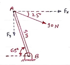 X – Component of force
Fx = 90 Cos 25 = 81.567 N
Y – Component of force
Fy = 90 Sin 25 = 38.036
Now taking moments about point B.
MB = [Fx x (3 Sin 65)] - [Fy x (3 Cos 65)]
MB = (81.65 x 2.72) – (38.036 x 1.27)
 = 221.843 – 48.31
MB = 173.53 N.m
If two forces acting simultaneously on a particle, be represented in magnitude & direction by two adjacent sides of parallelogram, then the diagonal passing through the point of intersection of two forces will represent the resultant in magnitude & direction.
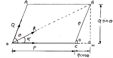
Consider two forces P & Q acting at a point represented by two sides OA & OC of parallelogram OABC.
Let, θ is the angle between two forces P & Q.
α be the angle between Force P & Resultant R.
Let’s draw a line BM perpendicular to OC which intersects OC at M.
In Δ CMB
Sin θ = BM / BC = BM / Q
BM = Q Sin θ
Also, Cos θ = CM / BC = CM / Q
CM = Q Cos θ
Now in Δ OMB,
We have, (OB) 2 = (OM) 2 + (BM)2
R2 = (OC + CM) 2 + (BM)2
R2 = (P + Q Cos θ) 2 + (Q Sin θ)2
= P2 + 2PQ Cos θ + Q2 Cos2 θ+ Q2 Sin2 θ
= P2 + 2PQ Cos θ + Q2(Cos2 θ+ Q2 Sin2 θ)
= P2 + 2PQ Cos θ + Q2
 Taking sq. Root,
R = √P2 + Q2 + 2PQ Cos θ . . . . Magnitude

Tanα = Q Sin θ / P + Q Cos θ . . . . Direction
Question )A ball is thrown with an initial velocity of 70 feet per second., at an angle of 35° with the horizontal. Find the vertical and horizontal components of the velocity.
Let v represent the velocity and use the given information to write v in unit vector form:
v =70(cos (35°))i+70(sin(35°))j
Simplify the scalars, we get:
v ≈57.34i+40.15j
Since the scalars are the horizontal and vertical components of v
Therefore, the horizontal component is 57.34 feet per second and the vertical component is 40.15 feet per second.
Question)A laser beam is aimed 15.95° above the horizontal at a mirror 11,648 m away. It glances off the mirror and continues for an additional 8570. m at 11.44° above the horizon until it hits its target. What is the resultant displacement of the beam to the target?
Solution
Vectors that are not at nice angles need to be dealt with. Break them up into their components
x1 = | r1 cos θ1 |
x1 = | (11,648 m)cos(15.95°) |
x1 = | 11,200 m |
y1 = | r1 sin θ1 |
y1 = | (11,648 m)sin(15.95°) |
y1 = | 3200 m |
x2 = | r2 cos θ2 |
x2 = | (8,570 m)cos(11.44°) |
x2 = | 8400 m |
y2 = | r2 sin θ2 |
y2 = | (8,570 m)sin(11.44°) |
y2 = | 1700 m |
Add vectors in the same direction with "ordinary" addition.
x = | 11,200 m + 8,400 m |
x = | 19,600 m |
y = | 3200 m + 1700 m |
y = | 4900 m |
Add vectors at right angles with a combination of PythagoreanTheorem for magnitude…
r = | √(x2 + y2) |
r = | √[(19,600 m)2 + (4,900 m)2] |
r = | 20,200 m |
And tangent for direction.
Tan θ = | y | = | 4,900 m |
|
x | 19,600 m |
| ||
θ = | 14.04° |
| ||
Statics
Static is the branch of mechanics which deals with the study of bodies at rest under a number of forces, the equilibrium, conditions of equilibrium, types of equilibrium, torque etc.
Equilibrium
A body is said to be in equilibrium if it is at rest or moving with uniform velocity.
In other words if the linear and angular acceleration of a body are zero, the body is said to be in equilibrium. Or we can say that when two or more forces act on a body such that their resultant or combining effect on the body is zero and the body retains its state of rest or of uniform motion then the body is said to be in equilibrium.
Example
A book lies on the table, suspended bodies, all stationary bodies , jump by using parachute.
Types of equilibrium
With respect to the state of a body, equilibrium may be divided into two categories:
1. Static equilibrium.
2. Dynamic equilibrium.
For latest information free computer courses and high impact notes visit
Static equilibrium
If the combined effect of all the forces acting on a body is zero and the body is in the state of rest then its equilibrium is termed as static equilibrium.
For example: All stationary bodies
Dynamic equilibrium
When a body is in state of uniform motion and the resultant of all forces acting upon it is zero then it is said to be in dynamic equilibrium.
For example: Jump by using parachute.
Conditions of equilibrium
There are two conditions of equilibrium are as follows
First condition of equilibrium
The first condition of equilibrium stated as follows:
Second condition of equilibrium
A body will be in rotational equilibrium when the vector sum of all the torques acting on it is zero.
Second condition of equilibrium
The second condition of equilibrium stated as follow:
A body will be in rotational equilibrium when the vector sum of all the torques acting on it is zero.
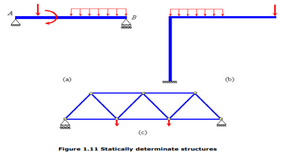
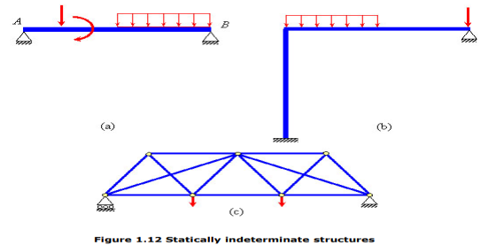
If the number of independent static equilibrium equations is not sufficient for solving for all the external and internal forces (support reactions and member forces, respectively) in a system, then the system is said to be statically indeterminate. A statically determinate system, as against an indeterminate one, is that for which one can obtain all the support reactions and internal member forces using only the static equilibrium equations. For example, for the system in Figure 1.10, idealized as one-dimensional, the number of independent static equilibrium equations is just 1 (R1 and R2), while the total number of unknown support reactions are 2 ( ), that is more than the number of equilibrium equations available. Therefore, the system is considered statically indeterminate. The following figures illustrate some example of statically determinate (Figures 1.11a-c) and indeterminate structures (Figures 1.12a-c).
1. If the body moves in any direction, it means that there is a resultant force acting on it. In other words, the horizontal component of all the forces (Σ H) and vertical component of all the forces (ΣV) must be zero. Mathematically,
Σ H = 0 and Σ V = 0
2. If there is rotation of body, without moving, that means there is couple acting. In other words, the resultant moment of all the forces (Σ M) must be zero. Mathematically,
Σ M = 0
3. If the body moves in any direction and at the same time it rotates about itself, if means that there is a resultant force and also a resultant couple acting on it. In other words, horizontal component of all the forces (Σ H), vertical component of all the forces (Σ V) and resultant moment of all the forces (Σ M) must be zero. Mathematically,
Σ H = 0 Σ V = 0 and Σ M = 0
4. If the body is completely at rest it means there is no force nor any couple acting on it. A little consideration will show, that in this case the following conditions are already satisfied:
Σ H = 0 Σ V = 0 and Σ M = 0
The above-mentioned equations are known as the conditions/equations of equilibrium.
Thus, the equations of equilibrium for two-dimensional coplanar force system are given by considering that the particle is present in x-y plane as shown in fig. Below, then the force can be resolved into i and j components.
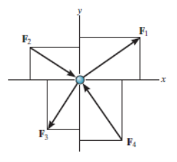
For equilibrium, the forces must add on to produce a zero-force output, i.e.,
Σ F = 0
ΣFxi + Σ Fy j = 0
Thus, for satisfying this vector equation, the x and y component must be zero as mentioned in earlier points. Hence,
ΣFx= 0
ΣFy= 0
Thus, for solving two-dimensional coplanar force problems using conditions of equilibrium, we can follow the below-mentioned procedure.
Free-Body Diagram.
• In any orientation, establish x and y axes.
• Then mark all the known and unknown forces in figure.
• Unknown forces are also assumed and plotted.
Equilibrium equation.
• Apply the equations of equilibrium, ΣFx= 0 and ΣFy= 0.
• The forces are directed as positive for those along positive axis and vice-versa.
• If the resultant comes out to be negative value, it means that the direction needs to be reversed for that is already considered.
As we know, the sufficient case for stating equilibrium for a body under combination of forces is Σ F = 0.
For any three-dimensional force system, as shown in Fig. Below, we can resolve the forces into their respective i, j, k components, so that
ΣFxi + Σ Fy j + ΣFz k = 0
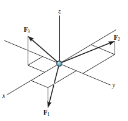
To satisfy this equation we require,
ΣFx= 0
ΣFy= 0
ΣFz= 0
These three equations state that the algebraic sum of the components of all the forces acting on the particle along each of the coordinate axes must be zero. Using these equations mentioned we can solve for maximum three of the unknowns, shown by coordinate direction angles or magnitudes of forces shown on the particle’s free-body diagram.
For solving three dimensional problem we can use the following procedure.
Free Body Diagram:
• In any orientation, establish x and y axes.
• Then mark all the known and unknown forces in figure.
• Unknown forces are also assumed and plotted.
Equations of Equilibrium.
• Apply the equations of equilibrium, ΣFx= 0, Σ Fy = 0 and ΣFz= 0.
• Initially we can display as a Cartesian vector if it becomes to solve the problem regularly substitute these vectors into Σ F = 0 and then set the i, j, k components equal to zero.
• If the resultant comes out to be negative value, it means that the direction needs to be reversed for that is already considered.
It states that if number of forces is acting simultaneously on a body, the algebraic sum of moments of all the forces about any point is equal to moment of their resultant about same point.
Mathematically,
∑(F xd) = (R x X)
Where, F = All forces acting on a body
d = ḻlar distance
R = Resultant of all forces
X = ḻlar distance of Resultant force about a point where moment is taken.
Use:- This theorem is useful to calculate or find the position or location of Resultant of non-concurrent force system
Lami’s Theorem: - (Body is subjected to three forces)
If three coplanar concurrent forces are in equilibrium then, the ratio of magnitude of any force to the sine of angle between the other two is constant.
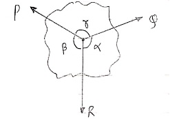
According to Lami’s Theorem:
Lami’s theorem can also be written as:If three coplanar concurrent forces acting at a point are in equilibrium, each force is proportional to the sine of angle between other two.
The body is said to be in equilibrium if the resultant of all forces acting on it is zero. There are two major types of static equilibrium, namely, translational equilibrium and rotational equilibrium.
Formulas
Concurrent force system
ΣFx=0
ΣFy=0
Parallel Force System
ΣF=0
ΣMO=0
Non-Concurrent Non-Parallel Force System
ΣFx=0
ΣFy=0
ΣMO=0