UNIT 2
Truss and Frames
Trusses are simply defined as triangulation of members to make the stabilized structure. Triangulation is the stable configuration mathematically. Generally, a truss has the members called as top chord, bottom chord, vertical chord and diagonal chord. The main functions of the trusses are:
- Carrying the loads from the over structures
- Providing adequate lateral stability to the entire structure
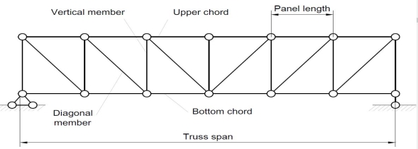
There are some basic assumptions in the designing process. It should be clarified that the construction of the trusses should conform with the design assumptions to avoid the unwanted failures due to the dispersion of the forces and loads. Following are the assumptions in truss design.
- Truss members will carry only the axial forces
- The nodes i.e the connections of the members are designed as pinned joints so that moments won’t be transferred to the members of the truss
- All the external loads and the reactions are act only on the nodes
- Generally, the truss should be in a plane.
Typically the members of the trusses are made as I sections, angles, T sections, Tube sections, Square sections and channel sections. I sections are more preferable as a optimized section in terms of the structural forces.
TYPES OF TRUSSES
- Simple truss – indicates a single triangular truss. These trusses are most often used as the roof trusses.
- Planar truss – as the name implies it is a two dimensional truss. If all the members and the nodes are in a planar surface, then this truss is a planar truss.
- Space frame truss – Contrast to planar truss, the members and the nodes are located in the three dimensional space. Electrical and telecom towers are the one of the simplest example that we are seeing in the day to day life.
Classification of Truss:-
Perfect truss Imperfect (unstable)
(stable) (n 2j R)
2j R)
(n=2j- R) over stable Deficient
Truss .
(Redundant)
(n< 2 j – R) (n< 2 j-R)
- Perfect truss :
A truss which does not collaspe under the action of
Load is called perfect truss.
Condition: n = 2 j-R
n= no. Of member 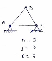
j = no of joints
R = no. Of reaction
In truss ABC, n = 3 & 2 j- R+3
So it is perfect truss
- Imperfect truss: A truss which does not collapse under the load is calledImperfect or unstable truss.
Here n 2j -R
2j -R
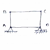
Over stable (Redundant Truss)
A truss in which n > 2j- R,
Then it is over stable truss.
Diagram


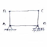
Deficient truss
It is a truss in which
N <2 j-R.
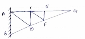
- Cantilever Truss:
A truss which is fixed on one side & free of Other end is called as cantilever truss.
.
Diagram
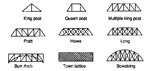
FORMS OF TRUSSES
1. Pratt truss
 Pratt truss form for the loads in gravity direction
 Pratt truss form for the uplift loads(loads opposite to gravity)
2. Warren truss

3. North light truss

4. Vierendeel truss

King post truss, Bowstring truss, Queen post truss, Flat truss, Lenticular truss are some other forms of trusses in the use of the industry.
Assumption made in the analysis:-
1) Given truss a perfect truss
2) The truss member are connected by joints only.
3) External loads are acting at the joints only.
4) All members are two force members.
5) The self- weight of members is neglected.
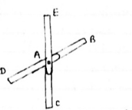
1) If when four members are connected At Engile joint in such a way That opposite members lie in a Single straight line
&
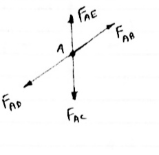
There is No external load acting at the joint Then Forces in the opposite members Are equal.
FAE = FAC & FAB = FAD.
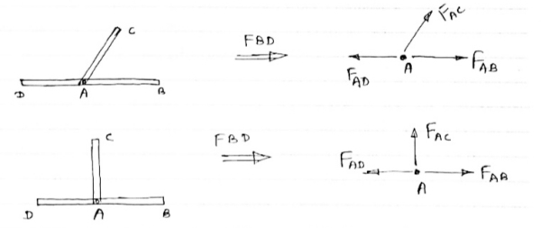
2) If There are only there members at a joint and Out of there, two are collinear and is inclined to first two or lar to first members, With no external load at joint,
Then,
a) Forces in the two opposite ( co- linear) members are equal. l.e FAD = FAB
b) The force in the inclined member is zero
l.e FAC =0
c) Force in the perpendicular member is zero
FAc = 0
4) If There are two member at a joint with one Member Horzintal& one vertical,
& there is no external load of joint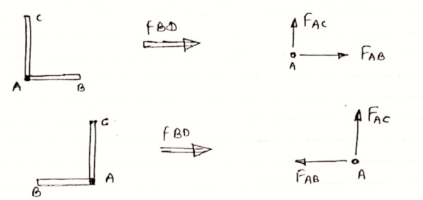
Then, both members are zero force member
Angle FAB=0
FAC =0
5) If there are only two members at joint With- one member vertical & other inclined & there is no external load of joint,

Then Both members are zero force members
i.e FAB = 0 & FAC =0
One member Horizontal & other inclined and
There is No external load at joint.

Then Both members are zero force members
FAB = 0 and FAC =0
6 ) if t here are only two members at a joint with one member Horizontal & other inclined and there is no External load at joint
Diagram

Then both members are zero force member
FAB=0 and FAC = 0
Perfect Truss
A Truss said to be Perfect Truss if it fulfil the below condition
m=2j-3
Where
m= number of members
j= number of joints
Perfect Truss does not collapse under loading.
Imperfect or Deficient Truss
If given member in the structure is less than the required member than it is called imperfect or deficient truss.
The condition of Deficient Truss is
m<2j-3
Where
m= number of members
j= number of joints
Deficient Truss collapse when we apply load on it.
Following are the assumptions made in finding the forces in the members of a frame.
- The frame is a perfect frame
- The frame is loaded only at the joint
- All the members of the frame are pin-jointed
- Self-weight of the members is neglected.
Forces in various members of a perfect frame may be found out either by analytical method or graphical method. Here, the discussion is confined to only analytical method.
A perfect frame can be analytically analysed by the following methods:
1 Method of joints or method of resolution
2 Method of sections or method of moments
Method of Joints
The free-body diagram of any joint is a concurrent force system in which the summation of moment will be of no help. Recall that only two equilibrium equations can be written
ΣFx=0 and ΣFy=0
This means that to solve completely for the forces acting on a joint, we must select a joint with no more than two unknown forces involved. This can be started by selecting a joint acted on by only two members. We can assume any unknown member to be either tension or compression. If negative value is obtained, this means that the force is opposite in action to that of the assumed direction. Once the forces in one joint are determined, their effects on adjacent joints are known. We then continue solving on successive joints until all members have been found.
Method of Sections
In this method, we will cut the truss into two sections by passing a cutting plane through the members whose internal forces we wish to determine. This method permits us to solve directly any member by analysing the left or the right section of the cutting plane.
To remain each section in equilibrium, the cut members will be replaced by forces equivalent to the internal load transmitted to the members. Each section may constitute of non-concurrent force system from which three equilibrium equations can be written.
ΣFH=0, ΣFV=0, and ΣMO=0
Because we can only solve up to three unknowns, it is important not to cut more than three members of the truss. Depending on the type of truss and which members to solve, one may have to repeat Method of Sections more than once to determine all the desired forces.
Centroid Definition
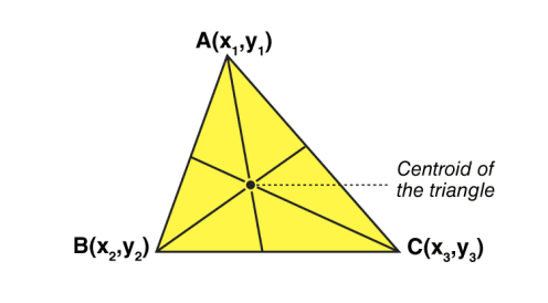
The centroid is the centre point of the object. The point in which the three medians of the triangle intersect is known as the centroid of a triangle. It is also defined as the point of intersection of all the three medians. The median is a line that joins the midpoint of a side and the opposite vertex of the triangle. The centroid of the triangle separates the median in the ratio of 2: 1. It can be found by taking the average of x- coordinate points and y-coordinate points of all the vertices of the triangle.
Centroid Theorem
The centroid theorem states that the centroid of the triangle is at 2/3 of the distance from the vertex to the mid-point of the sides.
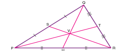
Suppose PQR is a triangle having a centroid V. S, T and U are the midpoints of the sides of the triangle PQ, QR and PR, respectively. Hence as per the theorem;
QV = 2/3 QU, PV = 2/3 PT and RV = 2/3 RS
Centroid of A Right Angle Triangle
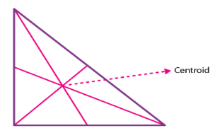
The centroid of a right angle triangle is the point of intersection of three medians, drawn from the vertices of the triangle to the midpoint of the opposite sides.
Centroid of a Square
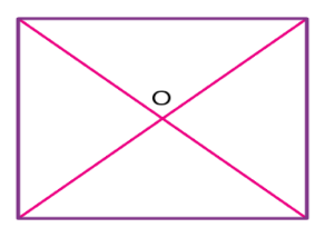
The point where the diagonals of the square intersect each other is the centroid of the square. As we all know, the square has all its sides equal. Hence it is easy to locate the centroid in it. See the below figure, where O is the centroid of the square.
Properties of centroid
The properties of the centroid are as follows:
- The centroid is the centre of the object.
- It is the centre of gravity.
- It should always lie inside the object.
- It is the point of concurrency of the medians.
Centroid Formula
Let’s consider a triangle. If the three vertices of the triangle are A(x1, y1), B(x2, y2), C(x3, y3), then the centroid of a triangle can be calculated by taking the average of X and Y coordinate points of all three vertices. Therefore, the centroid of a triangle can be written as:
Centroid of a triangle = ((x1+x2+x3)/3, (y1+y2+y3)/3)
Centre of gravity, in physics, an imaginary point in a body of matter where, for convenience in certain calculations, the total weight of the body may be thought to be concentrated. The concept is sometimes useful in designing static structures (e.g., buildings and bridges) or in predicting the behaviour of a moving body when it is acted on by gravity.

When a drum is stood on end, its centre of gravity (CG) is firmly supported, and the drum is in stable equilibrium (A). If the drum is tilted slightly to either side (B), the pull of gravity on this centre creates a torque, or turning force, around the new point of support and pulls the drum back to the stable position. A drum balanced on its rim (C) is in unstable equilibrium. Even a tiny displacement (D) will create a torque that will turn the drum farther from the unstable position.
In a uniform gravitational field the centre of gravity is identical to the centre of mass, a term preferred by physicists. The two do not always coincide, however. For example, the Moon’s centre of mass is very close to its geometric centre (it is not exact because the Moon is not a perfect uniform sphere), but its centre of gravity is slightly displaced toward Earth because of the stronger gravitational force on the Moon’s near side.
The location of a body’s centre of gravity may coincide with the geometric centre of the body, especially in a symmetrically shaped object composed of homogeneous material. An asymmetrical object composed of a variety of materials with different masses, however, is likely to have a centre of gravity located at some distance from its geometric centre. In some cases, such as hollow bodies or irregularly shaped objects, the centre of gravity (or centre of mass) may occur in space at a point external to the physical material—e.g., in the centre of a tennis ball or between the legs of a chair.
Published tables and handbooks list the centres of gravity for most common geometric shapes. For a triangular metal plate such as that depicted in the figure, the calculation would involve a summation of the moments of the weights of all the particles that make up the metal plate about point A. By equating this sum to the plate’s weight W, multiplied by the unknown distance from the centre of gravity G to AC, the position of G relative to AC can be determined. The summation of the moments can be obtained easily and precisely by means of integral calculus.
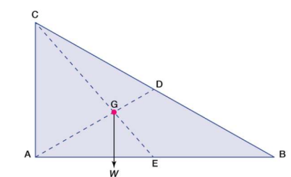
Centre of gravity. The red dot is the centre of gravity G.
The centre of gravity of anybody can also be determined by a simple physical procedure. For example, for the plate in the figure, the point G can be located by suspending the plate by a cord attached at point A and then by a cord attached at C. When the plate is suspended from A, the line AD is vertical; when it is suspended from C, the line CE is vertical. The centre of gravity is at the intersection of AD and CE. When an object is suspended from any single point, its centre of gravity lies directly beneath that point.
Center of mass
The centre of mass is a position defined relative to an object or system of objects. It is the average position of all the parts of the system, weighted according to their masses.
For simple rigid objects with uniform density, the center of mass is located at the centroid. For example, the center of mass of a uniform disc shape would be at its center. Sometimes the center of mass doesn't fall anywhere on the object. The center of mass of a ring for example is located at its center, where there isn't any material.

Figure 1: Center of mass for some simple geometric shapes (red dots).
For more complicated shapes, we need a more general mathematical definition of the center of mass. It is the unique position at which the weighted position vectors of all the parts of a system sum up to zero.
What is useful about the center of mass
The interesting thing about the center of mass of an object or system is that it is the point where any uniform force on the object acts. This is useful because it makes it easy to solve mechanics problems where we have to describe the motion of oddly-shaped objects and complicated systems.
For the purposes of calculation, we can treat an oddly-shaped object as if all its mass is concentrated in a tiny object located at the center of mass. We sometimes call this imaginary object a point mass.
If we push on a rigid object at its center of mass, then the object will always move as if it is a point mass. It will not rotate about any axis, regardless of its actual shape. If the object is subjected to an unbalanced force at some other point, then it will begin rotating about the center of mass.
How can we find the centerof mass of any object or system
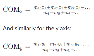
In general the center of mass can be found by vector addition of the weighted position vectors which point to the center of mass of each object in a system. One quick technique which lets us avoid the use of vector arithmetic is finding the center of mass separately for components along each axis. I.e:
For object positions along the x axis:
Centroids
Taking the simple case first, we aim to find the centroid for the area defined by a function f(x), and the vertical lines x = a and x = b as indicated in the following figure.
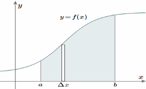
To find the centroid, we use the same basic idea that we were using for the straight-sided case above. The "typical" rectangle indicated is x units from the y-axis, and it has width Δx (which becomes dx when we integrate) and height y = f(x)
Generalizing from the above rectangular areas case, we multiply these 3 values x, f(x) and Δx, which will give us the area of each thin rectangle times its distance from the x-axis), then add them. If we do this for infinitesimally small strips, we get the x-coordinates of the centroid using the total moments in the x-direction, given by:

And, considering the moments in the y-direction about the x-axis and re-expressing the function in terms of y, we have:

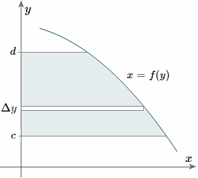
Notice this time the integration is with respect to y, and the distance of the "typical" rectangle from the x-axis is y units. Also note the lower and upper limits of the integral are c and d, which are on the y-axis.
Of course, there may be rectangular portions we need to consider separately. (I've used a different curve for the y case for simplification.)
Alternate method: Depending on the function, it may be easier to use the following alternative formula for the y-coordinate, which is derived from considering moments in the x-direction (Note the "dx" in the integral, and the upper and lower limits are along the x-axis for this alternate method).
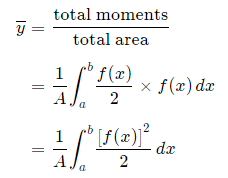
This is true since for our thin strip (width dx) the centroid will be half the distance from the top to the bottom of the strip.Another advantage of this second formula is there is no need to re-express the function in terms of y.
Centroids for Areas Bounded by 2 Curves
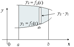
We extend the simple case given above. The "typical" rectangle indicated has width Δx and height y2 − y1, so the total moments in the x-direction over the total area is given by:

For the y coordinate, we have 2 different ways we can go about it.
Method 1: We take moments about the y-axis and so we'll need to re-express the expressions x2 and x1 as functions of y.

Method 2: We can also keep everything in terms of x by extending the "Alternate Method" given above:

Centre of mass
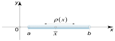
Suppose that we have a thin rod lying on the x−axis between x=a and x=b. At a point x, the rod has mass density (mass per unit length) ρ(x).
The center of mass of the rod is given by
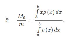
The integral in the numerator  is called the moment (or the first moment) of the one-dimensional object around zero.
The integral in the denominator  gives the total mass of the rod.