UNIT 4
Particle Dynamics
Newton’s first law states that, if a body is at rest or moving at a constant speed in a straight line, it will remain at rest or keep moving in a straight line at constant speed unless it is acted upon by a force. This postulate is known as the law of inertia. The law of inertia was first formulated by Galileo Galilei for horizontal motion on Earth and was later generalized by René Descartes. Before Galileo it had been thought that all horizontal motion required a direct cause, but Galileo deduced from his experiments that a body in motion would remain in motion unless a force (such as friction) caused it to come to rest.
Newton’s second law is a quantitative description of the changes that a force can produce on the motion of a body. It states that the time rate of change of the momentum of a body is equal in both magnitude and direction to the force imposed on it. The momentum of a body is equal to the product of its mass and its velocity. Momentum, like velocity, is a vector quantity, having both magnitude and direction. A force applied to a body can change the magnitude of the momentum, or its direction, or both. Newton’s second law is one of the most important in all of physics. For a body whose mass m is constant, it can be written in the form F = ma, where F (force) and a (acceleration) are both vector quantities. If a body has a net force acting on it, it is accelerated in accordance with the equation. Conversely, if a body is not accelerated, there is no net force acting on it.
Newton’s third law states that when two bodies interact, they apply forces to one another that are equal in magnitude and opposite in direction. The third law is also known as the law of action and reaction. This law is important in analyzing problems of static equilibrium, where all forces are balanced, but it also applies to bodies in uniform or accelerated motion. The forces it describes are real ones, not mere bookkeeping devices. For example, a book resting on a table applies a downward force equal to its weight on the table. According to the third law, the table applies an equal and opposite force to the book. This force occurs because the weight of the book causes the table to deform slightly so that it pushes back on the book like a coiled spring.
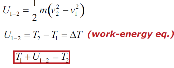
The kinetic energy T of a particle is T=1/2mv2
Work done to bring a particle from velocity v1 toa velocity v2.
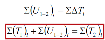
Work-Energy Relation for Particle Systems: ∑i
The kinetic energy T of a particle system is

Work done to bring a particle system from kinetic energy T1 to a kinetic energy T2
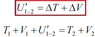
The work of all external forces other than gravitational and spring forces is
 (Work-energy eq.)
Work-Energy Relation for Particle Systems: System includes gravitational and elastic members. The work of all external forces other than gravitational and spring forces is
Angular momentum
The conserved quantity we are investigating is called angular momentum. The symbol for angular momentum is the letter L. Just as linear momentum is conserved when there are no net external forces, angular momentum is constant or conserved when the net torque is zero. We can see this by considering Newton’s 2nd law for rotational motion:
τ=dL/dt where τ is the torque. For the situation in which the net torque is zero, dLdt=0.
If the change in angular momentum ΔL is zero, then the angular momentum is constant; therefore,
L=constant (when net τ=0).
This is an expression for the law of conservation of angular momentum.
Linear momentum
The scientific definition of linear momentum is consistent with most people’s intuitive understanding of momentum: a large, fast-moving object has greater momentum than a smaller, slower object. Linear momentum is defined as the product of a system’s mass multiplied by its velocity. In symbols, linear momentum is expressed as p = mv.
Momentum is directly proportional to the object’s mass and also its velocity. Thus the greater an object’s mass or the greater its velocity, the greater its momentum. Momentum p is a vector having the same direction as the velocity v. The SI unit for momentum is kg · m/s.
The projectile is any object thrown into space upon which the only acting force is gravity. In other words, the primary force acting on a projectile is gravity. This doesn’t necessarily mean that the other forces do not act on it, just that their effect is minimal compared to gravity. The path followed by a projectile is known as a trajectory. A baseball batted or thrown and the instant the bullet exits the barrel of a gun are all examples of the projectile.
When a particle is thrown obliquely near the earth’s surface, it moves along a curved path under constant acceleration that is directed towards the center of the earth (we assume that the particle remains close to the surface of the earth). The path of such a particle is called a projectile and the motion is called projectile motion. Air resistance to the motion of the body is to be assumed absent in projectile motion.
In a Projectile Motion, there are two simultaneous independent rectilinear motions:
- Along the x-axis: uniform velocity, responsible for the horizontal (forward) motion of the particle.
- Along y-axis: uniform acceleration, responsible for the vertical (downwards) motion of the particle.
Accelerations in the horizontal projectile motion and vertical projectile motion of a particle: When a particle is projected in the air with some speed, the only force acting on it during its time in the air is the acceleration due to gravity (g). This acceleration acts vertically downward. There is no acceleration in the horizontal direction, which means that the velocity of the particle in the horizontal direction remains constant.
Let us consider a ball projected at an angle θ with respect to the horizontal x-axis with the initial velocity u as shown below:
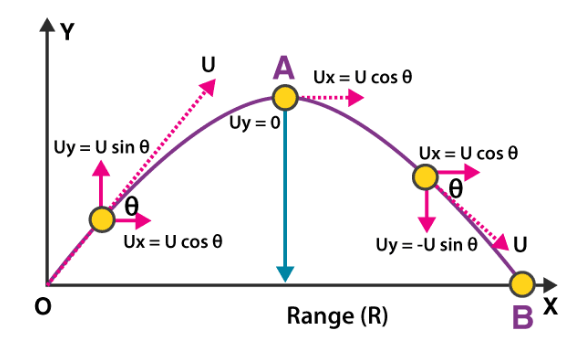
The point O is called the point of projection; θ is the angle of projection and OB = Horizontal Range or Simply Range. The total time taken by the particle from reaching O to B is called the time of flight.
For finding different parameters related to projectile motion, we can make use of differential equations of motions:
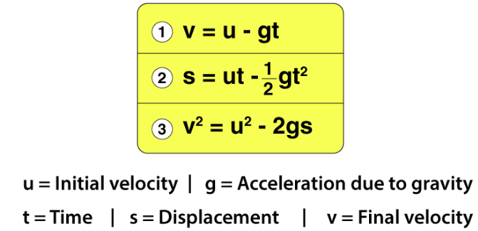
Total Time of Flight: Resultant displacement (s) = 0 in Vertical direction. Therefore, by using the Equation of motion:
Gt2 = 2(uyt – sy) [Here, uy = u sin θ and sy = 0]
i.e. gt2 = 2t × u sin θ
Therefore, the total time of flight (t):
TotalTimeofFlight(t)=2usinΘ/g
Horizontal Range: Horizontal Range (OA) = Horizontal component of velocity (ux) × Total Flight Time (t)
R = ucos θ× 2u×sinθg
Therefore, in a projectile motion the Horizontal Range is given by (R):
HorizontalRange(R)=u2sin2Θg
Maximum Height: It is the highest point of the trajectory (point A). When the ball is at point A, the vertical component of the velocity will be zero. i.e. 0 = (u sin θ)2– 2g Hmax [s = Hmax , v = 0 and u = u sin θ]
Therefore, in projectile motion, the Maximum Height is given by (Hmax):
MaximumHeight(Hmax)=u2sin2Θ / 2g
The equation of Trajectory:
EquationofTrajectory=xtanΘ−gx2 / 2u2cos2Θ
This is the Equation of Trajectory in projectile motion, and it proves that the projectile motion is always parabolic in nature.
Classification of statically determinate beams
- Cantilever beams
- Simply supported beams
- Overhanging beams.
Types of applied loads on the beams
- Concentrated loads
- Uniformly distributed loads
- Uniformly varying loads
- Externally applied moments.
Definitions
Shear force: The resultant vertical force either to the right or to the left of the section is known as shear force.
Bending moment: The algebraic sum of the moments of all forces either to the left or the right at a section in a beam is known as bending moment.
Shear force diagram: A diagram in which ordinate represents shear force and abscissa represents the position of the section is called shear force diagram.
Bending moment diagramA diagram in which ordinate represents bending moment and abscissa represents the position of the section is called bending moment diagram.
SFD and BMD for Standard Cases
1. Cantilever subjected to:
- a concentrated load at free end
- Uniformly distributed load over entire span
- Uniformly varying load over entire span
2. Simply supported beam subjected to:
- a concentrated load
- Uniformly distributed load over entire span
- Uniformly varying load over entire span
- An external moment
3. Overhanging beam subjected to a concentrated load at free end.
Nature of SF and BM variation
Load S.F. B.M.
- No load Constant Linear
- Uniformly distributed load Linear Parabolic
- Uniformly varying Parabolic Cubic
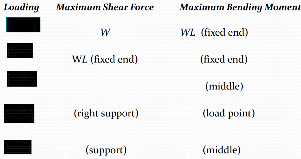
- Maximum shear force and bending
- Moment values for standard cases
Maximum shear force and bending moment values for standard cases
Types of Beam: -
- Simply supported beam –
A beam which is just resting on the supports at the end without any connection is known as simply supported beam. It is generally used for vertical landing system.

2. Overhanging Beam –
A beam which is supported at the intermediate point other than ends is called as overhanging beam. Here portion of beam is extended beyond the support
a)(singly overhanging beam)
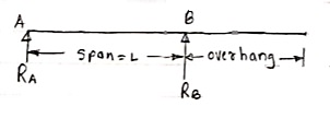
b) (doubly overhanging beam)

Cantilever Beam –
A beam which is fixed at one end is called as cantilever beam

Here, there are three reactions components:
- Vertical reaction at A (RVA)
- Horizontal reaction at A (RHA)
- Fixing moment at A (MA)
We can assume any direction for above components.
3. Continuous Beam:
A beam having more than two support is called as continuous beam.

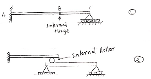
4. Compound Beam:
When two or more beams are joined together by using internal hinge; or when one beam rests over another beam by using internal roller, then such beam is called as compound beam.
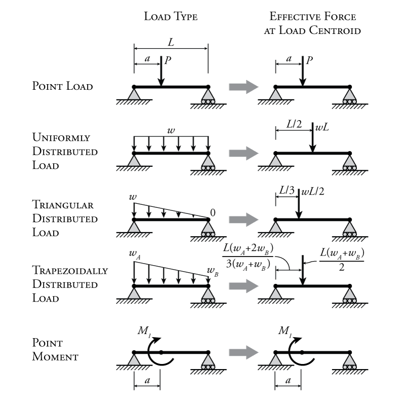
A beam is usually horizontal, and the applied load is vertical. Following are the different types of loads.
- Concentrated or Point Load: Act at a point.
- Uniformly Distributed Load: Load spread along the length of the Beam.
- Uniformly Varying Load: Load spread along the length of the Beam, Rate of varying loading point to point.

Sign conversion for Shear force and bending moment
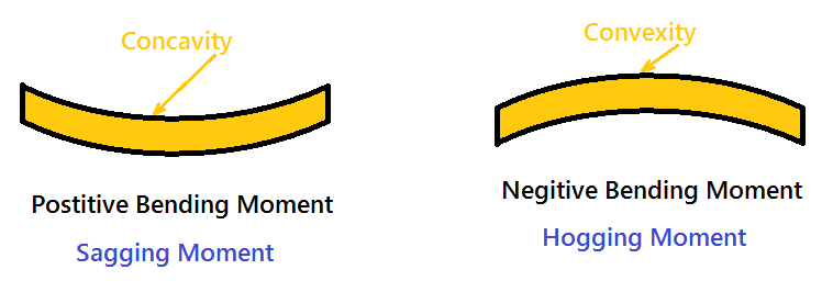
For a simply supported beam, If a point load is acting at the centre of the beam. Imagine a section X-X divide the beam into two portions. See the pic below.
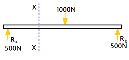
A simply supported beam is carrying a load (point load) of 1000N at its middle point. The reactions support will be equal to 500N(Ra=Rb). The section X-X make the beam into two parts.
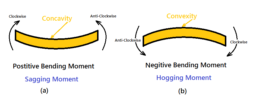
The moment of all the forces, i.e., load and reaction to the left of section X-X is Clockwise .The moment of all the forces, i.e., load and reaction to the right of section X-X are Anti-Clockwise.
So this makes the beam a Sagging moment (Concavity). Here the bending moment is Positive. See (a). If the left portion makes an anticlockwise moment and the right portion of the section makes a Clockwise moment, then it is hogging moment. Bending moment Negative.
Similarly for Shear force is positive when the left portion of the section goes upwards or the right portion of the section goes downwards.
Shear force is Negative when the left portion of the section goes downwards, or the right portion of the section goes upwards.
Shear force refers to the force acting along on a surface. Basically, the force forms no inclination/angle to the surface on which it is acting on. Within a beam, the shear force at any section is basically the algebraic sum of the lateral forces acting on either side of the section. For example, take a look at this beam:
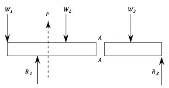
Consider a beam carrying loads W1, W2 and W3 with R1 and R2 as the support reactions. If we cut the beam at section AA, then since the resultant forces at the left of section AA is F upwards, then the shearing force at section AA is F downwards.
On the other hand, the bending moment refers to the internal rotational moments that cause a section to bend. In the case of a beam, it can be calculated as the algebraic sum of the moments about the section of all forces acting on either side of the section, where a sagging moment will make the beam concave (positive) upwards at that section, and vice versa for a hogging moment (i.e. negative).
This diagram basically is an example of the shear force and bending moment of a simply supported beam subjected to a point load on the centre:
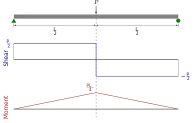
It is important to calculate both the shear force and bending moment because it is extremely handy when it comes to structural design. By determining the values of the shear force and bending moment across a structure/structural member, we can accordingly decide the appropriate material or size that can help it to withstand these internal forces and moments. This is crucial because using the wrong material or size can ultimately cost the structure/structural elements its integrity for failing to support the designed loads.
Shear Force and Bending Moment Diagrams for a Simply-Supported Beam Under A Uniform Load
After the support reactions are calculated, the shear force and bending moment diagrams can be drawn.
Shear force is the force in the beam acting perpendicular to its longitudinal (x) axis. For design purposes, the beam's ability to resist shear force is more important than its ability to resist an axial force. Axial force is the force in the beam acting parallel to the longitudinal axis.
The following is a drawing of a simply-supported beam of length L under a uniform load, q:

This beam has the following support reactions:
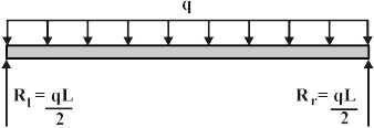
WhereRl and Rr are the reactions at the left and right ends of the beam, respectively.
The shear forces at the ends of the beam are equal to the vertical forces of the support reactions. The shear force F(x) at any other point x on the beam can be found by using the following equation.

Where x is the distance from the left end of the beam.
Shear force diagrams are simply plots of the shear force (on the y-axis) versus the position of various points along the beam (on the x-axis). Thus, the following is the generalized shear force diagram for the beam shown above.
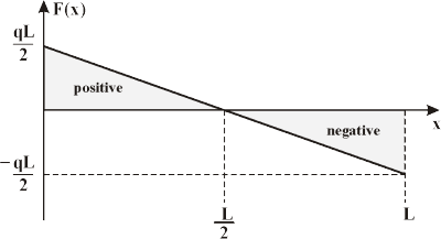
The bending moment at any point along the beam is equal to the area under the shear force diagram up to that point. (Note: For a simply-supported beam, the bending moment at the ends will always be equal to zero.)
To calculate the bending moment the beam must be broken up into two sections:
(a) | One from x = 0 to x = L/2 and |
(b) | The other from x = L/2 to x = L. |
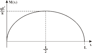
The bending moment M(x) at any point x along the beam can be found by using the following equations:

Bending moment diagrams are simply plots of the bending moment (on the y-axis) versus the position of various points along the beam (on the x-axis). Thus, the following is the generalized bending moment diagram for the beam shown above.
A point where a plane curve changes from the concave to the convex relative tosome fixed line; equivalently, if the function determining the curve has a secondderivative, this derivative changes sign at this point. Also known as inflection point.
These are the points at which the deflection curve of the body changes the sign of curvature. In other terms, we can say that the inflection points are the points where the shear force changes its direction from +ve to –ve and vice versa.
Consider the figure for the shear force and bending moment diagram and the inflection points in the beam.
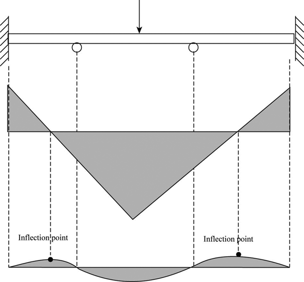
From the above figure, it can be clearly stated that the inflection points are the points on the bending moment diagram at which the shear force have zero value.
At the inflection point, the bending moment curve changes in their concavity.
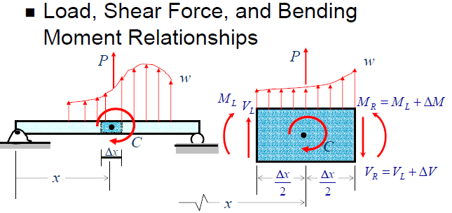
To draw the shear force and bending moment diagram, use the following relationship between the unit loads w, shear force F and the moment M.
To find the location of zero shears the reactions are to be estimated at the start. Find the shear force equation and equate it to zero to get the location of inflection point.
Generally, there are two methods, which are used to find the point of zero shear. The first method is where the random point is taken along the beam at any distance to estimate the moment relationship about that point and equating it to zero. The other method is based on the similar triangle concept applied on the shear force diagram.
Hence, the point of inflection is the point of zero shears. The point of the contraflexure is the point in the bending moment diagram, where the magnitude of bending moment is zero.