UNIT 1
ELECTRIC AND MAGNETIC FIELDS IN A MEDIUM
If the electric field in a space is E is vacuum and we put a material medium with permittivity ε in that region, the electric field reduces by a factor of ε/ε0 which is equal to the dielectric constant of the medium.
Due to presence of the material medium, the polarized field in the medium due to the electric field somewhat cancels its effect and as a result the decrease in net electric field is observed.
We have studied about Dielectric constant. Dielectric constant it is a quantity measuring the ability of a substance to store electrical energy in an electric field.
Or
The ratio of the permittivity of the substance to the permittivity of the free space
Dielectric constant is also called Relative Permittivity Dielectric Constant is expressed by Greek letter kappa ‘κ’. It is dimensionless quantity.
It is mathematically expressed as:
κ = 
Where,
- κ is the dielectric constant
- 𝜺 is the permittivity of the substance
- 𝜺0 is the permittivity of the free space
Dielectric Strength
- It is defined as the maximum electric field which the material can sustain without breaking down.
- When a high electric field is applied to the dielectric, the outer electrons get detached from their parent atoms. The dielectric then behaves as a conductor. In other words, every dielectric starts conducting when if an external field is applied to it. This value of electric field depends on the nature of material of dielectric and is called dielectric strength.
We will see the effect of presence of medium other than vacuum on the field.
The great success of Maxwell’s equations lies partly in their simple prediction of electromagnetic waves and their simple characterization of materials in terms of conductivity σ [Siemens m-1], permittivity ε [Farads m-1], and permeability μ [Henries m-1].
In vacuum we find
σ = 0, ε = εo, and μ = μo,
Where εo = 8.8542×10⁻¹² and μo = 4π×10-7.
For reference, Maxwell’s equations are:
Maxwell’s four equations are given by
∇× = −∂
= −∂ /∂t (1)
∇× = J + ∂
 /∂t (2)
∇· = ρ (3)
∇· = 0 (4)
The electromagnetic properties of most media can be characterized by the constitutive relations:
 =ε
=ε (5)
(5)
 =μ
=μ (6)
(6)
J =σ (7)
(7)
In contrast, the nano-structure of media can be quite complex and requires quantum mechanics for its full explanation. Fortunately, simple classical approximations to atoms and molecules suffice to understand the origins of σ, ε, and μ, as discussed below in that sequence.
Permittivity
The permittivity εo of free space is 8.854×10⁻¹² farads/meter, where
 =εo
=εo  .
.
The permittivity ε of any material deviates from εo for free space if applied electric fields induce electric dipoles in the medium; such dipoles alter the applied electric field seen by neighbouring atoms.
Electric fields generally distort atoms because  pulls on positively charged nuclei (f=q
 [N]) and repels the surrounding negatively charged electron clouds. The resulting small offset d of each atomic nucleus of charge +q relative to the center of its associated electron cloud produces a tiny electric dipole in each atom, as suggested in Figure: 1(a).
In addition, most asymmetric molecules are permanently polarized, such as H2O or NH3, and can rotate within fluids or gases to align with an applied field. Whether the dipole moments are induced, or permanent and free to rotate, the result is a complete or partial alignment of dipole moments as suggested in Figure: 1(b).
These polarization charges generally cancel inside the medium, as suggested in Figure: 1(b), but the immobile atomic dipoles on the outside surfaces of the medium are not fully cancelled and therefore contribute the surface polarization charge ρsp
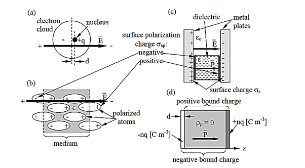
Figure 1: Polarized media.
Figure:1(c) suggests how two charged plates might provide an electric field  that polarizes a dielectric slab having permittivity ε > εo. The electric field
  is the same in vacuum as it is inside the dielectric (assuming no air gaps) because the path integral of
  from plate to plate equals their voltage difference V in both cases. The electric displacement vector
  e =ε
e =ε  and therefore differs.] We associate the difference between
  o =εo
o =εo (vacuum) and
  ε=ε
ε=ε (dielectric) with the electric polarization vector P , where:
 = ε
= ε =εo
=εo  +
+ = εo
= εo  (1+
(1+ ) (8)
) (8)
The polarization vector  is defined by (8) and is normally parallel to
  in the same direction, as shown in Figure: 1(c); it points from the negative surface polarization charge to the positive surface polarization charge (unlike
  , which points from positive charges to negative ones).
As suggested in (8),  = εo
= εo  ,
,
Where χ is defined as the dimensionless susceptibility of the dielectric. Because nuclei are bound rather tightly to their electron clouds, χ is generally less than 3 for most atoms, although some molecules and crystals, particularly in fluid form, can exhibit much higher values.
P simply equals the product of the number density n of these dipoles and the average vector electric dipole moment of each atom or molecule,  =q
=q , where d is the offset (meters) of the positive charge relative to the negative charge:
 =nq
=nq (9)
(9)
Gauss’s law relates  to charge density ρ [Cm-2], but we now have two types of density: that of free charges ρf, including ions and surface charges on conductors, and that of any locally un-neutralized polarization charge ρp bound within charge-neutral atoms or molecules. Gauss’s law says:
∇• =ρf (10)
Where ρf is the free charge density [Cm-3]
We can derive a relation similar to (10) for  by treating materials as distributed bound positive and negative charges with vacuum between them; the net bound charge density is designated the polarization charge density ρp [Cm-3]. Then in the vacuum between the charges
  =εo
=εo  and (10) becomes:
ε0∇• =ρf+ρo (11)
From ∇ •(8), we obtain
∇• =ε0∇•
=ε0∇• +∇•
+∇• =ρf .
=ρf .
Combining this with (11) yields:
∇• =−ρp (12)
The negative sign in (12) is consistent with the fact that  , unlike
  , is directed from negative to positive polarization charge, as noted earlier. Outside a polarized dielectric the polarization
  is zero, as suggested by Figure:1(d).
Note that the net polarization charge density is ±nq for only an atomic-scale distance d at the boundaries of the dielectric, where we model the positive and negative charge distributions within the medium as continuous uniform rectilinear slabs of density ± nq [Cm-3].
These two slabs are offset by the distance d. If  is in the z direction and arises from n dipole moments p=qd per cubic meter, where d is the offset [m] of the positive charge relative to the negative =charge, then (12) can be integrated over a volume V that encloses a unit area of the left-hand face of a polarized dielectric [see Figure: 1(d)] to yield the polarization vector
  inside the dielectric:
 =∫V ∇•
 dv=−∫V ρp dv =nq
Some special dielectric media are spontaneously polarized, even in the absence of an externally applied E. This occurs for highly polarizable media where orientation of one electric dipole in the media can motivate its neighbours to orient themselves similarly, forming domains of atoms, molecules, or crystal unit cells that are all polarized the same.
Such spontaneously polarized domains are illustrated for magnetic materials in Figure 2. As in the case of ferromagnetic domains, in the absence of externally applied fields, domain size is limited by the build-up of stored field energy external to the domain; adjacent domains are oriented so as to largely cancel each other. Such ferroelectric materials have large effective values of ε, although D saturates if E is sufficient to produce ~100% alignment of polarization. They can also exhibit hysteresis as do the ferromagnetic materials.
PERMEABILITY
The permeability μ of free space is μo = 4π×10-7Henries/meter by definition,
Where
 =μ
=μ
The permeability μ of matter includes the additional contributions to  from atomic magnetic dipoles aligning with the applied
  . These magnetic dipoles and their associated magnetic fields arise either from electrons orbiting about atomic nuclei or from spinning charged particles, where such moving charge is current. All electrons and protons have spin ±1/2 in addition to any orbital spin about the nucleus, and the net spin of an atom or nucleus can be non-zero. Their magnetic fields are linked to their equivalent currents by Ampere’s law, ∇×H=J +∂D ∂t . Quantum theory describes how these magnetic moments are quantized at discrete levels, and for some device quantum descriptions are necessary. In this text we average over large numbers of atoms, so that
  =μ
=μ accurately characterizes media, and quantum effects can be ignored.
In any medium the cumulative contribution of induced magnetic dipoles to B is characterized by the magnetization M , which is defined by:
B =μH =μ0(H +M)=μoH (1+χm) (13)
Where χm is the magnetic susceptibility of the medium. Because of quantum effects χm for diamagnetic materials is slightly negative so that μ < μo; examples include silver, copper, and water.
The sharp difference between normal materials with μ≅μo and ferromagnetic materials having μ >> μo is due to the spontaneous alignment of atomic magnetic dipoles in the same direction so as to increase the applied field, reorienting the remaining dipoles. That is, if the susceptibility of a material is above some threshold, then the atomic magnetic dipoles spontaneously align over regions of size limited by grain structure or energy considerations, as suggested in Figure 2(a and b). These regions of nearly perfect alignment are called magnetic domains. These domains are normally quite small (perhaps micron-size) so as to minimize the stored magnetic energy μH.
In this system, if only energy considerations control domain size, then the sizes of those domains oriented in the general direction of the applied magnetic field grow as that field increases, while other domains shrink, as suggested in Figure 2(c). Since domain walls cannot easily move across grain walls, the granular structure of the material can be engineered to control magnetic properties. If domain walls move easily, the magnetic susceptability χm is large.
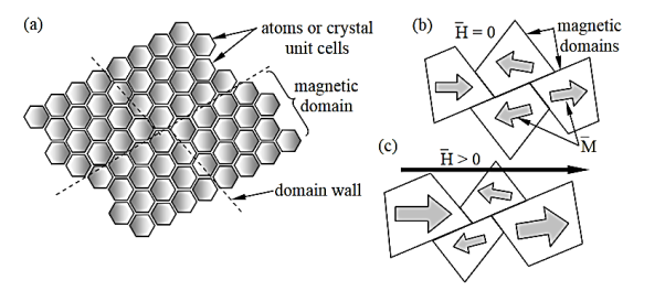
Figure 2: Magnetic domains in ferromagnetic materials.
At sufficiently high magnetic fields all domains will expand to their maximum size and/or rotate in the direction of H. This corresponds to the maximum value of M and magnetic saturation. The resulting typical non-linear behaviour of the magnetization curve relating B and H for ferromagnetic materials is suggested in Figure 2(a). The slope of the B vs. H curve is μ near the origin and ~μo beyond saturation. If the domains resist change and dissipate energy when doing so, the hysteresis curve of Figure 2. (b) results. It can be shown that the area enclosed by the figure is the energy dissipated per cycle as the applied H oscillates.
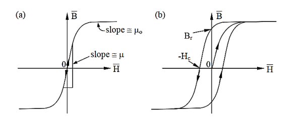
Figure:3 Magnetization curve and hysterisis loop for a ferromagnetic material
Hard magnetic materials have large values of residual flux density B and magnetic coercive force or coercivity Hc, as illustrated. Br corresponds to the magnetic strength B of this permanent magnet with no applied H. The magnetic energy density Wm=B•H/2 ≅0 inside permanent magnets because H=0, while Wm =μoH2[Jm-3] outside. To demagnetize a permanent magnet. We can apply a magnetic field H of magnitude Hc, which is the field strength necessary to drive B to zero.
If we represent the magnetic dipole moment of an atom by m, where m for a current loop of magnitude I and area  A is
A is  IA [A m], then it can be shown that the total magnetization M of a medium is nm [A m-1] via the same approach used to derive P=np for the polarization of dielectrics; n is the number of dipoles per m3.
Note: We have seen that simple characterization of materials in terms of conductivity σ [Siemens m-1], permittivity ε [Farads m-1], and permeability μ [Henries m-1].we already read about permittivity and permeability. Conductivity is explained in next section.
Susceptibility is the extent to which a given material gets polarised when it is kept in an electric field.
If the material gets polarised more, it will set up an internal field which opposes the external field which will then reduce the total electric flux through that material. Therefore, electric susceptibility affects the electric permittivity of the medium.
Greater the level of polarisation, lower will be the electric permitivity
For most linear dielectric materials, the polarization P is directly proportional to the average electric field strength E so that the ratio of the two, P/E, is a constant that expresses an intrinsic property of the material.
The electric susceptibility, χe, in the centimetre-gram-second (cgs) system, is defined by this ratio; that is,
χe = P/E.
In the metre-kilogram-second (mks) system, electric susceptibility is defined slightly differently by including the constant permittivity of a vacuum, ε0, in the expression; that is,
χe = P/(ε0E).
In both systems the electric susceptibility is always a dimensionless positive number. Because of the slight difference in definition, the value of the electric susceptibility of a given material in the mks system is 4π times its value in the cgs system.
Susceptibility of polar dielectric depends upon the temperature whereas Susceptibility of non-polar, dielectric is independent of the temperature.
Magnetic susceptibility (χ)
If H is the applied magnetizing field intensity and M is the amount of magnetization of the material,
Then χ = 
χ = 0 in vacuum
χ = +ve for paramagnetic and Ferro magnetic materials
χ = -ve for diamagnetic materials
Units: It has no units.
Relation between dielectric constant and susceptibility
Electric displacement, also known as dielectric displacement and usually denoted by D, is a vector field in a non-conducting medium, a dielectric.
In a dielectric material, the presence of an electric field E causes the bound positive and negative charges in the material to slightly separate, inducing a local electric dipole moment. The electric displacement field "D" is defined as
D= 𝜺0E+P
D =
Electric displacement
E = External electric field in which the dielectric is placed
𝜺0 = the permittivity of the free space
P = Polarization Density
In S.I. System, Unit of Electric displacement is C/m2.
D =  E+P
E+P
D=  E and P =
  eE
eE
Substituting these values in eq (1), we get
 E =
E =  E+
E+ eE
eE
 =
=  +
+ e
e
 = 1 +
= 1 + 
But
κ =  = Dielectric constant
κ = 1 + 
Clearly values of κ for all dielectric is greater than one, and for empty space  e=0 and κ =1.
CONDUCTIVITY
Conduction in metals and n-type semiconductors involves free electrons moving many atomic diameters before they lose momentum by interacting with atoms or other particles. Acceleration induced by the small applied electric field inside the conductor restores electron velocities to produce equilibrium current. The total current density J [Am-2] is proportional to the product of the average electron velocity v [ms-1] and the number density n [m-3] of free electrons. A related conduction process occurs in ionic liquids, where both negative and positive ions can carry charge long distances.
In metals there is approximately one free electron per atom and in warm n-type semiconductors there is approximately one free electron per donor atom, where the sparse donor atoms are easily ionized thermally. Since, for non-obvious reasons, the average electron velocity  is proportional to
  , therefore
  =−en
=−en = σ
= σ . As the conductivity σ approaches infinity the electric field inside a conductor approaches zero for any given current density
  .
.
Warm donor atoms in n-type semiconductors can be easily ionized and contribute electrons to the conduction band where they move freely. Only certain types of impurity atoms function as donors those that are most easily ionized. As the density of donor atoms approaches zero and as temperature declines, the number of free electrons and the conductivity approach very low values that depend on temperature and any alternative ionization mechanisms that are present.
In p-type semiconductors the added impurity atoms readily trap nearby free electrons to produce a negative ion; this results in a corresponding number of positively ionized semiconductor atoms that act as “holes”. As a result, any free electrons typically move only short distances before they are trapped by one of these holes. Moreover, the threshold energy required to move an electron from a neutral atom to an adjacent positive ion is usually less than the available thermal energy, so such transfers occur rapidly, causing the hole to move quickly from place to place over long distances. Thus, holes are the dominant charge carriers in p-type semiconductors, whereas electrons dominate in n-type semiconductors.
More broadly, semiconductors have a conduction band in which free electrons can propagate long distances; this band is separated by energy of one or a few electron volts from the valence band in which electrons cannot move. The conduction band is not a location, it is a family of possible electron wave states. When electrons are excited from the valence band to the conduction band by some energetic process, they become free to move in response to electric fields.
Semiconductor conductivity is approximately proportional to the number of free electrons or holes produced by the scarce impurity atoms, and therefore to the doping density of those impurity atoms. Easily ionized impurity atoms are the principal mechanism by which electrons enter the conduction band, and impurities that readily trap adjacent electrons are the principal mechanism by which holes enter and move in the valence band.
The current leakage processes in insulators imprecisely resemble electron and hole conduction in semiconductors, and can include weak surface currents as well as bulk conduction; microscopic flaws can also increase conductivity. The conductivities of typical materials are listed in Table 1.
Table 1: Nominal conductivities σ of common materials [Siemens m-1]

In some exotic materials the conductivity is a function of direction and can be represented by the 3×3 matrix σ; such materials are not addressed here. Some materials exhibit superconductivity, or infinite conductivity. In these materials pairs of electrons become loosely bound magnetically and move as a unit called a Cooper pair.
Quantum mechanics prevents these pairs from colliding with the lattice and losing energy. Because the magnetic binding energy for these pairs involves electron spins, it is quite small. Normal conductivity returns above a threshold critical temperature at which the pairs are shaken apart, and it also returns above some threshold critical magnetic field at which the magnetic bonds coupling the electrons break as the electron spins all start to point in the same direction. Materials having critical temperatures above 77K (readily obtained in cryogenic refrigerators) are difficult to achieve.
The finite number of such pairs at any temperature and magnetic field limits the current to some maximum value; moreover, that current itself produces a magnetic field that can disrupt pairs. Even a few pairs can move so as to reduce electric fields to zero by short-circuiting the normal electrons until the maximum current carrying capacity of those pairs is exceeded. If the applied fields have frequency f > 0, then the Cooper pairs behave much like collision less electrons in plasma and therefore the applied electric field can penetrate that plasma to its skin depth. Those penetrating electric fields interact - with a small number of normal electrons to produce tiny losses in superconductors that increase with frequency.
Maxwell equations are of fundamental importance since they describe the whole of classical electromagnetic phenomena.
Maxwell's Equations are a set of 4 complicated equations that describe the world of electromagnetics. These equations describe how electric and magnetic fields propagate, interact, and how they are influenced by objects.
Maxwell was one of the first to determine the speed of propagation of electromagnetic (EM) waves was the same as the speed of light - and hence to conclude that EM waves and visible light were really the same thing.
These equations are rules the universe uses to govern the behaviour of electric and magnetic fields. A flow of electric current will produce a magnetic field. If the current flow varies with time (as in any wave or periodic signal), the magnetic field will also give rise to an electric field. Maxwell's Equations shows that separated charge (positive and negative) gives rise to an electric field - and if this is varying in time as well will give rise to a propagating electric field, further giving rise to a propagating magnetic field.
From a classical perspective, light can be described as waves of electromagnetic radiation. As such, Maxwell equations are very useful to illustrate a number of the characteristics of light including polarization.
We are just to stating these equations without derivation. Since our goal is simply to apply them, the usual approach will be followed.
Maxwell’s first equation (Gauss' Law for Electric Fields)
Gauss' Law is the first of Maxwell's Equations which dictates how the Electric Field behaves around electric charges. Gauss' Law can be written in terms of the Electric Flux Density and the Electric Charge Density as:
∇·E = ρ/ε0
0r
∇·D = ρ
Hence, Gauss' law is a mathematical statement that the total Electric Flux exiting any volume is equal to the total charge inside. Hence, if the volume in question has no charge within it, the net flow of Electric Flux out of that region is zero. If there is positive charge within a volume, then there exists a positive amount of Electric Flux exiting any volume that surrounds the charge. If there is negative charge within a volume, then there exists a negative amount of Electric Flux exiting (i.e. the Electric Flux enters the volume).
Maxwell’s second equation (Faraday's Law)
Faraday figured out that a changing Magnetic Flux within a circuit (or closed loop of wire) produced an induced EMF, or voltage within the circuit. Maxwell gives his second equation from this.
Faraday's Law tells us that a magnetic field that is changing in time will give rise to a circulating E-field. This means we have two ways of generating E-fields - from Electric Charges (or flowing electric charge, current) or from a magnetic field that is changing.
∇×E = −∂B/∂t (2)
Maxwell’s third equation (Ampere's Law)
Ampere's Law tells us that a flowing electric current gives rise to a magnetic field that circles the wire. In addition to this, it also says that an Electric Field that is changing in time gives rise to a magnetic field that encircles the E-field - this is the Displacement Current term that Maxwell himself introduced.
This means there are 2 ways to generate a solenoidal (circulating) H-field - a flowing electric current or a changing Electric Field. Both give rise to the same phenomenon.
The modified form of Ampere's Law s given by Maxwell’s third equation
∇×H = J + ∂D/∂t
Maxwell’s four equation (Gauss' Magnetism law)
We know that Gauss' Law for Electric Fields states that the divergence of the Electric Flux Density D is equal to the volume electric charge density. But the second equation, Gauss' Magnetism law states that the divergence of the Magnetic Flux Density (B) is zero.
Why? Why isn't the divergence of B equal to the magnetic charge density?
Well - it is. But it just so happens that no one has ever found magnetic charge - not in a laboratory or on the street or on the subway. And therefore, until this hypothetical magnetic charge is found, we set the right side of Gauss' Law for Magnetic Fields to zero:
∇·B = 0
Now, you may have played with magnets when you were little, and these magnetic objects attracted other magnets similar to how electric charges repel or attract like electric charges. However, there is something special about these magnets - they always have a positive and negative end. This means every magnetic object is a magnetic dipole, with a north and South Pole. No matter how many times you break the magnetic in half, it will just form more magnetic dipoles. Gauss' Law for Magnetism states that magnetic monopoles do not exist - or at least we haven't found them yet.
Maxwell’s four equations are given by
∇·E = ρ/ε0 (1)
∇×E = −∂B/∂t (2)
∇×H = J + ∂D/∂t (3)
∇·B = 0 (4)
These equations illustrate the unique coexistence in nature of the electric field and the magnetic field. The first two equations give the value of the given flux through a closed surface, and the second two equations give the value of a line integral around a loop. In this notation,
∇=(∂/∂x, ∂/∂y, ∂/∂z)
E is the electric vector
B is the magnetic induction
ρ is the electric charge density
j is the electric current density
ε0 is the permittivity of free space
c is the speed of light.
In addition to Maxwell equations, the following identities are useful:
J = σE (5)
D = εE (6)
B = μH (7)
Here,
D is the electric displacement
H is the magnetic vector
σ is the specific conductivity
ε is the dielectric constant (or permittivity)
μ is the magnetic permeability
Maxwell’s equations characterize macroscopic matter by means of its permittivity ε, permeability μ, and conductivity σ, where these properties are usually represented by scalars and can vary among media. There are media for which ε, μ, and σ are represented by matrices, complex quantities, or other means.
Maxwell’s equations strongly constrain the behaviour of electromagnetic fields at boundaries between two media having different properties, where these constraint equations are called boundary conditions.
We will study the boundary conditions governing field components perpendicular to the boundary, and the parallel field components one by one.
One result of these boundary conditions is that waves at boundaries are generally partially transmitted and partially reflected with directions and amplitudes that depend on the two media and the incident angles and polarizations.
Static fields also generally have different amplitudes and directions on the two sides of a boundary. Some boundaries in both static and dynamic situations also possess surface charge or carry surface currents that further affect the adjacent fields.
Boundary conditions for perpendicular field components
The boundary conditions governing the perpendicular components of  and
and  follow from the integral forms of Gauss’s laws:
Gauss’s law for 
 …………(1)
Gauss’s law for 
 …………(2)
We may integrate these equations over the surface S and volume V of the thin infinitesimal pillbox illustrated in Figure 3. The pillbox is parallel to the surface and overlaps it, half being on each side of the boundary. The thickness δ of the pillbox approaches zero faster than does its surface area S, where S is approximately twice the area A of the top surface of the box.
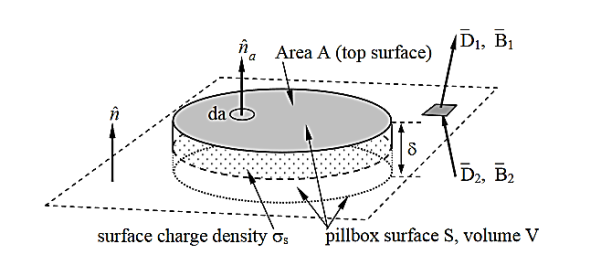
Figure 3: Elemental volume for deriving boundary conditions for perpendicular field components.
Beginning with the boundary condition for the perpendicular component D⊥, we integrate Gauss’s law over the pillbox to obtain
 ……………(3)
Where ρs is the surface charge density [Coulombs m-2]. The subscript s for surface charge ρs distinguishes it from the volume charge density ρ [C m-3]. The pillbox is so thin (δ→ 0) that: 1) the contribution to the surface integral of the sides of the pillbox vanishes in comparison to the rest of the integral, and 2) only a surface charge q can be contained within it, where ρs = q/A = lim ρδ as the charge density ρ→∞ and δ→ 0. Thus (3) becomes D1⊥ - D2⊥ = ρs, which can be written as:
 -
-  )= ρs ……………(3)
(boundary condition for  ⊥)
⊥)
Where  is the unit vector normal to the boundary and points into medium 1. Thus the perpendicular component of the electric displacement vector
  changes value at a boundary in accord with the surface charge density ρs.
Because Gauss’s laws are the same for electric and magnetic fields, except that there are no magnetic charges, the same analysis for the magnetic flux density  in (2) yields a similar boundary condition:
 -
-  )= 0 ……………(4)
Thus, the perpendicular component of  must be continuous across any boundary.
Boundary conditions for parallel field components
The boundary conditions governing the parallel components of  and
and  follow from Faraday’s and Ampere’s laws:
Faraday’s laws
 ……………(5)
Ampere’s laws
 ……………(6)
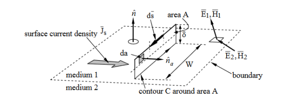
Figure 4: Elemental contour for deriving boundary conditions for parallel field components.
Note : In the expressions all quantities have vector sign, don’t confused it with bar sign.
We can integrate these equations around the elongated rectangular contour C that straddles the boundary and has infinitesimal area A, as illustrated in Figure 4 We assume the total height δ of the rectangle is much less than its length W, and circle C in a right-hand sense relative to the surface normal  a.
a.
 ……………(7)
Where the integral of  over area A approaches zero in the limit where δ approaches zero too; there can be no impulses in
  . Since W ≠ 0, it follows from (7) that E1// - E2// = 0, or more generally:
Boundary condition for E//
 -
-  )= 0
)= 0
Thus, the parallel component of  must be continuous across any boundary. A similar integration of Ampere’s law, (6), under the assumption that the contour C is chosen to lie in a plane perpendicular to the surface current Js and is traversed in the right-hand sense, yields:
 ……………(8)
Where we note that the area integral of ∂D/∂t approaches zero as δ →0, but not the integral over the surface current Js, which occupies a surface layer thin compared to δ. Thus H1// −H2 // =Js , or more generally:
(boundary condition for H//)
 -
-  )=
)=  ……………(9)
Where  is defined as pointing from medium 2 into medium 1. If the medium is nonconducting
  = 0.
= 0.
A simple static example illustrates how these boundary conditions generally result in fields on two sides of a boundary pointing in different directions.
Consider the magnetic fields H1 and H2 illustrated in Figure 5, where μ2 ≠ μ1, and both media are insulators so the surface current must be zero. If we are given H1, then the magnitude and angle of H2 are determined because H// and B⊥ are continuous across the boundary, where  i =μi
i =μi  i . More specifically, H2// =H1//, and:
 ……………(10)
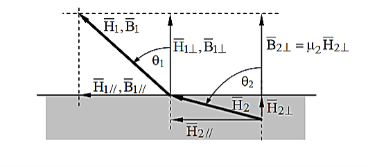
Figure 5: Static magnetic field directions at a boundary.
It follows that:

……………(11)
Thus, θ2 approaches 90 degrees when μ2 >> μ1, almost regardless of θ1, so the magnetic flux inside high permeability materials is nearly parallel to the walls and trapped inside, even when the field orientation outside the medium is nearly perpendicular to the interface. The flux escapes high-μ material best when θ1 ≅90°. This phenomenon is critical to the design of motors or other systems incorporating iron or nickel. If a static surface current  flows at the boundary, then the relations between
  and
and  are altered along with those for
  and
and  . Similar considerations and methods apply to static electric fields at a boundary, where any static surface charge on the boundary alters the relationship between
  and
and  . Surface currents normally arise only in non-static or “dynamic” cases.
Wave is nothing but a pattern of disturbance which propagates and carry energy with it. You can produce a wave on a rope by moving one end of the rope up and down. The wave produces on rope needs a medium to propagate and here medium is rope itself. This type of waves is known as mechanical waves. But in the case of Electromagnetic waves, they don't need a medium to propagate. Electromagnetic waves are waves that are created as a result of variations of electric field and a magnetic field. Or we can say that Electromagnetic waves are nothing but changing magnetic and electric fields. Electromagnetic waves are also known to be solutions of Maxwell's equations. And Maxwell's equations are the fundamental equations of electrodynamics. Electromagnetic waves can transmit energy and travel through a vacuum.
Light waves are examples of electromagnetic waves. Generally, Electromagnetic waves are shown by a sinusoidal graph.
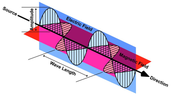
Figure 6
As shown in figure Electromagnetic waves consist of time-varying electric and magnetic fields and they are perpendicular to each other and these both fields are also perpendicular to the direction of propagation of waves.
Maxwell’s four equations are given by
∇·E = ρ/ε0 (1)
∇×E = −∂B/∂t (2)
∇×H = J + ∂D/∂t (3)
∇·B = 0 (4)
These equations illustrate the unique coexistence in nature of the electric field and the magnetic field. The first two equations give the value of the given flux through a closed surface, and the second two equations give the value of a line integral around a loop. In this notation,
∇=(∂/∂x, ∂/∂y, ∂/∂z)
E is the electric vector
B is the magnetic induction
ρ is the electric charge density
j is the electric current density
ε0 is the permittivity of free space
c is the speed of light.
In addition to Maxwell equations, the following identities are useful:
J = σE (5)
D = εE (6)
B = μH (7)
Here,
D is the electric displacement
H is the magnetic vector
σ is the specific conductivity
ε is the dielectric constant (or permittivity)
μ is the magnetic permeability
Free space or non-conducting medium. We know that non conducting medium means no current so conductivity is zero i.e. σ=0
So current density J=σE will also become zero as σ=0 Also free space means no charges which leads to ρ=0. These points mentioned below.
(a) No condition current i.e σ=0, thus J=0 ( J=σE)
(b) No charges (i.e ρ=0)
For the case of no charges or currents, that is, j = 0 and ρ = 0, and a homogeneous medium. Using these the Maxwell equation can rewritten as-
∇.D=0 or ∇.E=0 as ρ=0 (12)
∇ x E= -dB/dt or ∇ x E= -μ dH/dt because B = μH (13)
∇ x H=d D/dt or ∇ x H = ε dE/dt (J=0) and D = εE (14)
∇.B=0 (15)
WAVE EQUATION IN TERMS OF ELECTRIC FIELD INTENSITY, E
Now taking curl of second Maxwell’s equation (13) ,we get
∇ x(∇ x E)=- μ d/dt (∇ x H)
Applying standard vector identity, that is [∇ *(∇*E)=∇(∇.E)-∇2E] on left hand side of above equation, we get
∇ (∇ .E)-∇2E= -μ d/dt (∇ x H) (16)
Substituting equations (13) and (14) in equations (16) we get
-∇2E= – με d/dt (dE/dt)
Or ∇2E=με d 2 E/dT2 (17)
Equation (17) is the required wave equation in terms of electric field intensity, E for free space. This is the law that E must obey.
WAVE EQUATION IN TERMS OF MAGNETIC FIELD INTENSITY, H
Take curl of fourth Maxwell’s equation (14) we get
∇x(∇xH)=ε d/dt(∇xE)
Applying standard vector identity that is
[∇*(∇*H)=∇ (∇.H)-∇2H]
On left side of above equation, we get
∇(∇.H)-∇2H= ε d/dt(∇xE) (18)
Substituting equations (14) and (13) in equation (18) we get
-∇2H= – μεd/dt(dH/dt)
Or
∇2H=με d2H/dt2 (19)
Equations (19) is the required wave equation in terms of magnetic field intensity, H and this is the law that H must obey
For vacuum μ=μ0 and ε=ε0, equations (17) and (19) will become
∇2 E=μ0ε0 d2E/dt2 (20)
And ∇2H= μ0ε0 d2H/dt2 (21)
This leads to an expression for the velocity of propagation
From equation both equations (20) and (21) have the form of the general wave equation for a wave

(x,t) traveling in the x direction with speed v. Equating the speed with the coefficients, we derive the speed of electric and magnetic waves, which is a constant that we symbolize with “c”
It is useful to note that in vacuum
c2=1/ε0μ0
Where μ0 is the permeability of free space

Let us rewrite the equation (20) and (21) for one dimension.
Or d 2 E/dx2 = μ0ε0 d 2 E/dt2 (22)
d2H/dx2 = μ0ε0 d2H/dt2 (23)
The simplest solutions to the differential equations (22) and (23) are sinusoidal wave functions:
E(x) = Emax cos(kx-t) (24)
B(x) = Bmax cos(kx-t) (25)
Where k = 2π/λ is the wavenumber, ω = 2πƒ is the angular frequency, λ is the wavelength, f is the frequency and ω /k=f=v= c.
In an electromagnetic wave, electric and magnetic field vectors are perpendicular to each other and at the same time are perpendicular to the direction of propagation of the wave. This nature of electromagnetic wave is known as Transverse nature.
Maxwell proved that both the electric and magnetic fields are perpendicular to each other in the direction of wave propagation. He considered an electromagnetic wave propagating along positive x-axis. When a rectangular parallelepiped was placed parallel to the three, co-ordinate axis, the electric and magnetic fields propagate sinusoidal with the x-axis and are independent of y and z-axis.
A wave in which the values of variable are constant in a plane perpendicular to the direction of propagation of the wave is called plane wave. These planes may also termed as wave fronts.
Solutions of Maxwell’s Equations - Uniform Plane Waves
The sources of time varying electromagnetic fields are time varying charges and currents, whether man-made or naturally occurring. However, examination of Maxwell’s equations shows that, even in empty space (with no sources), and fields cause each other. This means that, although these fields must originate in source regions, they can propagate through source-free regions. Because solutions in source regions are very hard to obtain, let us consider what kind of fields can exist in source-free regions.

These equations are still very complicated (4 different partial derivatives). Let’s try to find simple solutions. We do this by making assumptions. After finding simplest solutions, we:
(i) Find what kind of source would generate this type of field (waves).
(ii) Show that these simple solutions are useful approximations to real electromagnetic waves.
Assumption for Solution:
Can we find a solution such that:
1.) No variation exists in x and y directions.
2.)  or
or  also is oriented along one of the axes.
Ampere’s Law becomes:

Or, with our assumptions:

Compare for transmission line:

In a similar manner,
 ………….(1)
Faraday’s Law becomes:
 ………….(2)
Thus, if  is only in the
  direction, then is only in the .If we differentiate (2) with respect to z, we get:

Substitute from (2),

We get

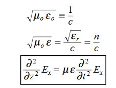
This is called the wave equation.
Compare for transmission line: (same).

We will assume dielectric media; lossless:

Dimensional analysis:


In the units we are using:
By exactly the same method, we also get:
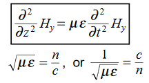
For example, the same equation is true for  and
and  . Thus,
  and
and  must have the same type of functional dependence. This wave equation still has many possible solutions. In fact, it can be shown by direct substitution that

Are the solutions

t is important to note that f1 and f2 can be any function.
The field we find directly from the equation:

Suppose
 …………(3)
Differentiate (3) with respect to z
 …………(4)
Integrate with respect to time
 …………(5)

This leads to a new quantity that relates the electric and magnetic fields:


Rewriting:
Units of  =
=  =
=  = Ω
= Ω
 0 = Impedance of free space =
  =377 Ω
 = impedance of a lossless dielectric =
  =
= =
= 
Note that  and
and  are in time phase and space quadrature
The directions of the vectors are such that:

This vector 

 , always points in the direction of propagation. These types of waves are called Uniform Plane Electromagnetic Waves.
“Plane” refers to the fact that, at any instant in time, the surfaces of constant phase are planes (here, constant).
“Uniform” means no variation in transverse direction. The wave derived here is one oscillating at a single frequency. The frequency is determined by the source. If the source has multiple frequencies, so will the wave. In communications, modulating a carrier wave results in multiple frequencies. But before we can study such fields, we must thoroughly understand single frequency sinusoidal waves.
Transverse Nature
In this section we will study the variation of field of  and
and  of an em plane wave with space and time.
Variation With Space
First we will consider the variation with space. Suppose a plane em wave is propagating along x axis. Then the values of the field vectors  and
and  will be constant on any plane parallel to YZ plane. That is:
For 
 =
= =
= =
= = 0 …………(1)
For 
 =
= =
= =
= = 0 …………(2)
From Maxwell’s equation for free space, we have
∇.E=0
Therefore
 +
+ +
+ =0
=0
Which gives
 =0 …………(3)
Also From Maxwell’s equation for free space, we have
∇.B=0 we have ∇.H=0 as B = μH
Hence
 +
+ +
+ =0
=0
Which gives
 =0 …………(4)
The equation (3) and (4) show that there is no variation of  and
and  along the X axis. In other words, there is no variation in the longitudinal component of
  and
and  .
.
Time Variation of  and
and 
The Maxwell’s equation in free space can be written as:
∇ x E= -dB/dt or ∇ x E= -μ  because B = μH
Comparing the rectangular components, we find:
 -
-  = -μ
= -μ  …………(5)
 -
-  = -μ
= -μ  …………(6)
 -
-  = -μ
= -μ  …………(7)
Applying the condition listed in equation (1), from equation (5), we find:
 -
-  =0
=0
 =0 …………(8)
Again using Maxwell’s equation for free space is:
∇ x H=  = Ɛ
= Ɛ
Comparing the rectangular components, we can write:
 -
-  = Ɛ
= Ɛ  …………(9)
 -
-  = Ɛ
= Ɛ …………(10)
 -
-  = Ɛ
= Ɛ …………(11)
Again, using the conditions listed in equation (2) gives:
 -
-  = 0
= 0
 = 0 …………(12)
From equation (8) and (12), we find that there is no variation in the values of  and
and  with time. That is
  and
and  neither vary with space nor with time. So at the most they can have constant value. But the constant values of
  and
and  contribute nothing towards the wave because for the wave the field vectors must possess oscillatory nature. This shows that there is no longitudinal component of the field vectors in the electromagnetic wave. In other words, for the purpose of discussing of the wave nature, we may put
  =0
=0
Now from equation 6 and 7 by putting  = 0, we find:
 = μ
= μ  …………(13)
 = - μ
= - μ  …………(14)
Similarly putting  =0 in equation (10) and (11) we find:
 = - Ɛ
= - Ɛ …………(10)
 = Ɛ
= Ɛ …………(11)
These relations show that in the em values  and
and  are related to each other. Also
  and
and  are related to each other, and their time or space variation are not zero. From this we conclude that the em wave is transverse in nature.