Unit 3
Ac circuits
- Poly phase one which produces many phase simultaneously
- Instead of saying poly phase we use 3 ɸ supply there for 3 ɸ system
- Generation of electrical supply is 3 ɸ only using alternator (AC generator ) by 3 separate winding placed 1200 a part from each other one winding for I phase
 3 windings
3 phase =  = 1290 apart each winding
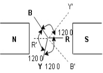
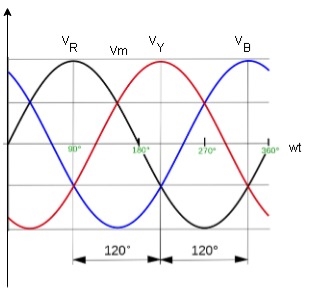
Here R is the reference phase globally in generation of 3 Ø ac
Ø = 0
Y is the 2nd phase generated and placed apart from R phase Ø = -1200
B is the 3rd phase generated and placed apart from R phase Ø = -2400
- More output : for same size the output of 3Ø machine is always higher than single 1 Ø phase machine.
- Smaller size : for producing same output the size of 3 phase machine is always smaller than of single phase machine
- 3 phase motor are self starting as the 3 Ø ac supply is capable of producing a rotating magnetic file when applied are self starting 1 Ø motor need additional starter winding
- More power is transmitted : in the transmitted system it is possible to transmitted more power using 3 Ø system rather than 1 Ø system, by using conductor of same cross sectional .
- Smaller cross sectional area of conductor
ɡȴ same amount of power is to transmitted than cross sectional area of conductor used for 3 Ø system is small as compared to that for single Ø system.
Connections
The sequence in which the 3 phase reach their maximum +ve values Sequence is R-Y-B 3 colours used to denoted 3 phase are red’, yellow, blue.
The direction of rotation of 3 Ø machines depends on phase sequence. ɡȴ the phase sequence is changed ie R-B-Y than the direction of rotation will be reversed.
- Phasor Diagram
Consider equation ①
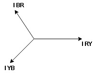
Note : we are getting resultant line current IR by subtracting 2 phase currents IRY and IBR  take phase currents at reference as shown
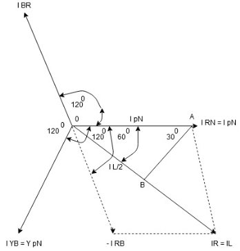
Cos 300 =
 =
= 

- Complete phases diagram for delta connected balanced Inductive load.
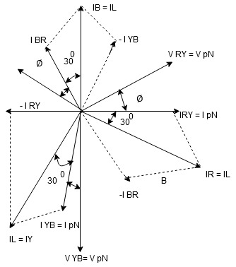
Phase current IYB lags behind VYB which is phase voltage as the load is inductive
- Power relation for delta load star power consumed per phase
PPh =VPhIPh Cos Ø
For 3 Ø total power is
PT= 3 VPhIPh Cos Ø …….①
For star
VL and IL = IPh (replace in ①)
 PT = 3
  IL Cos Ø
 PT = 3
  VL IL Cos Ø – watts
For delta
VL =VPhand IL =  (replace in ①)
PT = 3VL
= 3VL  Cos Ø
Cos Ø
 PT
PT VLIL Cos Ø – watts
Total average power
P =  VLIL Cos Ø – for ʎ and
  load
load
K (watts)
Total reactive power
Q =  VLIL Sin Ø – for star
  delta load
K (VAR)
Total Apparent power
S =  VL IL – for star
  delta load
K (VA)
- Power triangle
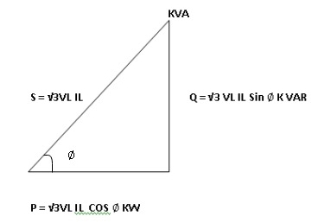
- Relation between power
In star and power in delta
Consider a star connected balance load with per phase impedance ZPh
We know that for
VL = VPhandVL=  VPh
VPh
Now IPh = 
 VL = =
And VPh=
 IL =
IL = ……①
……①
Pʎ =  VL IL Cos Ø ……②
Replacing ① in ② value of IL
 Pʎ =
Pʎ =  VL IL
VL IL  Cos Ø
Cos Ø
 Pʎ =
Pʎ =  ….A
….A
- Now for delta
IPh =
 IPh= =
And IL = IPh
IPh
 IL =
IL = X
X  …..①
…..①
P =
=  VL IL Cos Ø ……②
Replacing ② in ① value of IL
P =
=  Cos Ø
Cos Ø
 P
P =
=  …..B
…..B

Pʎ from …A
 …..C
…..C
 =
=  P
P
We can conclude that power in delta is 3 time power in star from …C
Or
Power in star is  time power in delta from ….D
- Step to solve numerical
- Calculate VPh from the given value of VL by relation
For star VPh = 
For delta VPh= VL
2. Calculate IPh using formula
IPh = 
3. Calculate IL using relation
IL = IPh - for star
IL = IPh- for delta
4. Calculate P by formula (active power)
P =  VL IL Cos Ø – watts
5. Calculate Q by formula (reactive power)
Q =  VL IL Sin Ø – VAR
6. Calculate S by formula (Apparent power)
S =  VL IL– VA
Balanced load : balanced load is that in which magnitude of all impedance connected in the load are equal and the phase angle of them are also equal
Ie Z1 Z2
Z2  Z3 then it is unbalanced load
To derive the relations between line and phase currents and voltages of a star connected system, we have first to draw a balanced star connected system.
Suppose due to load impedance the current lags the applied voltage in each phase of the system by an angle ϕ. As we have considered that the system is perfectly balanced, the magnitude of current and voltage of each phase is the same. Let us say, the magnitude of the voltage across the red phase i.e. magnitude of the voltage between neutral point (N) and red phase terminal (R) is VR.
Similarly, the magnitude of the voltage across yellow phase is VY and the magnitude of the voltage across blue phase is VB.
In the balanced star system, magnitude of phase voltage in each phase is Vph.
∴ VR = VY = VB = Vph
We know in the star connection, line current is same as phase current. The magnitude of this current is same in all three phases and say it is IL.
∴ IR = IY = IB = IL, Where, IR is line current of R phase, IY is line current of Y phase and IB is line current of B phase. Again, phase current, Iph of each phase is same as line current IL in star connected system.
∴ IR = IY = IB = IL = Iph.
Now, let us say, the voltage across R and Y terminal of the star connected circuit is VRY.
The voltage across Y and B terminal of the star connected circuit is VYBBR.
From the diagram, it is found that
VRY = VR + (− VY)
Similarly, VYB = VY + (− VB)
And, VBR = VB + (− VR)
Now, as angle between VR and VY is 120o(electrical), the angle between VR and – VY is 180o – 120o = 60o(electrical).
Thus, for the star-connected system line voltage = √3 × phase voltage.
Line current = Phase current
As, the angle between voltage and current per phase is φ, the electric power per phase is

Three phase power and its measurement. (Simple
Numerical Problems)
1. The input power to a 3-phase a.c. Motor is measured as 5kW. If the voltage and current to the motor are 400V and 8.6A respectively, determine the power factor of the system?
Power P=5000W,
Line voltage VL = 400 V,
Line current, IL = 8.6A and
Power, P =√3 VLIL cos φ
Hence
Power factor = cos φ = P √3 VLIL
= 5000 √3 (400) (8.6)
= 0.839
2. Two wattmeters are connected to measure the input power to a balanced 3-phase load by the two-wattmeter method. If the instrument readings are 8kW and 4kW, determine (a) the total power input and (b) the load power factor.
(a)Total input power,
P=P1 +P2 =8+4=12kW
(b) tan φ =√3(P1 − P2)/(P1 + P2)
=√3 (8 – 4) / (8 + 4)
=√3 (4/12)
=√3(1/3)
= 1/ √3
Hence φ= tan−1 1 √3 =30◦
Power factor= cos φ= cos 30◦ =0.866
3. Two wattmeters connected to a 3-phase motor indicate the total power input to be 12kW. The power factor is 0.6. Determine the readings of each wattmeter.
If the two wattmeters indicate P1 and P2 respectively
Then P1 + P2 = 12kW | ---(1) |
Tan φ =√3(P1 − P2)/(P1 + P2)
And power factor=0.6= cos φ.
Angle φ= cos−10.6=53.13◦ and
Tan 53.13◦ =1.3333.
Hence
1.3333 =√3(P1 − P2)/12
From which,
P1 − P2 = 12(1.3333) /√3
i.e. P1 −P2 =9.237kW ----(2)
Adding Equations (1) and (2) gives:
2P1 = 21.237
i.e P1 = 21.237/2
= 10.62kW Hence wattmeter 1 reads 10.62kW From Equation (1), wattmeter 2 reads
(12−10.62)=1.38kW
4. Three loads, each of resistance 30, are connected in star to a 415 V, 3-phase supply. Determine
(a) the system phase voltage, (b) the phase current and (c) the line current.
A ‘415 V, 3-phase supply’ means that 415 V is the line voltage, VL
(a) For a star connection, VL =√3Vp Hence phase voltage, Vp = VL/√3
= 415 /√3
= 239.6 V or 240 V
Correct to 3 significant figures
(b) Phase current, Ip = Vp/Rp
= 240/30
= 8 A
(c) For a star connection, Ip = IL Hence the line current, IL = 8 A
5. Three identical coils, each of resistance 10ohm and inductance 42mH are connected (a) in star and (b) in delta to a 415V, 50 Hz, 3-phase supply. Determine the total power dissipated in each case.
(a) Star connection
Inductive reactance,
XL =2πf L =2π (50) (42×10−3) =13.19
Phase impedance,
Zp =√(R2 +XL2)
=√(102 +13.192) =16.55
Line voltage, VL =415 V
And phase voltage,
VP =VL/√3=415/√3=240 V.
Phase current,
Ip =Vp/Zp =240/16.55=14.50 A. Line current,
IL =Ip =14.50 A.
Power factor= cos φ=Rp/Zp =10/16.55 =0.6042 lagging.
Power dissipated,
P =√3 VLIL cos φ =√3 (415) (14.50)(0.6042) = 6.3kW (Alternatively,
P =3I2R =3(14.50)2(10)=6.3kW)
(b) Delta connection
VL = Vp = 415 V,
Zp = 16.55_, cos φ = 0.6042 lagging (from above). Phase current,
Ip =Vp/Zp =415/16.55=25.08A. Line current,
IL =√3Ip =√3(25.08)=43.44A.
Power dissipated,
P =√3 VLIL cos φ
=√3 (415)(43.44)(0.6042) = 18.87kW
(Alternatively,
P =3I2R
=3(25.08)2(10) =18.87 kW)
6. A 415V, 3-phase a.c. Motor has a power output of 12.75kW and operates at a power factor of 0.77 lagging and with an efficiency of 85 per cent. If the motor is delta-connected, determine (a) the power input, (b) the line current and (c) the phase current.
(a) Efficiency=power output/power input.
Hence
(85/100)=12.750 power input from which, Power input = 12. 750 × 10085
= 15 000W or 15Kw
(b) Power, P=√3 VLIL cos φ, hence
(c) line current,
IL = P/ √3 (415) (0.77)
= 15 000/ √3 (415) (0.77)
= 27.10A
(d) For a delta connection, IL =√3 Ip,
Hence
Phase current, Ip = IL/√3
= 27.10 /√3
= 15.65A
7. A 400V, 3-phase star connected alternator supplies a delta-connected load, each phase of which has a resistance of 30_ and inductive reactance 40_. Calculate (a) the current supplied by the alternator and (b) the output power and the kVA of the alternator, neglecting losses in the line between the alternator and load.
A circuit diagram of the alternator and load is shown in Fig.
(a) Considering the load:
Phase current, Ip =Vp/Zp
Vp =VL for a delta connection,
Hence Vp =400V.
Phase impedance,
Zp =√ (R2+XL2)
=√ (302 +402) =50

Figure
Hence Ip =Vp/Zp =400/50=8A.
For a delta-connection,
Line current, IL =√3 Ip =√3 (8) =13.86 A.
Hence 13.86A is the current supplied by the alternator.
(b) Alternator output power is equal to the power Dissipated by the load
I.e. P =√3 VLIL cos φ, Where cos φ = Rp/Zp = 30/50 = 0.6.
Hence P =√3 (400) (13.86) (0.6) = 5.76kW.
Alternator output kVA,
S =√3 VLIL =√3 (400) (13.86)
9.60 kVA.
Introduction
In the physical sciences, process engineering and product quality assurance, measurement is the activity of obtaining and comparing physical quantities of real-world objects and events. Established standard objects and events are used as units, and the process of measurement gives a number relating the item under study and the referenced unit of measurement. Measurement generally involves using an instrument as a physical means of determining a quantity or variable. The instrument serves as an extension of human faculties and enables the man to determine the value of an unknown quantity which unaided human faculties cannot measure. An instrument may be defined as a device for determining the value or magnitude of a quantity or variable. Measuring instruments, and formal test methods which define the instrument's use, are the means by which the variables and the relations between variables are obtained
The instruments may be classified as follows:
i) Mechanical, electrical and electronic instruments
Ii) Absolute and secondary instruments
Iii) Manual and automatic instruments
Iv) Analogue and digital instruments
v) Self operated and power operated instruments
Vi) Self contained and remote indicating instruments
Mechanical, Electric and Electronic Instruments
Mechanical instruments
The first instruments were mechanical in nature and the principles on which these instruments worked are even in vogue today. The earliest scientific instruments used the same three essential elements as our modern instruments do. These elements are a detector, an intermediate transfer device and an indicator, recorder or a storage device.
These instruments are very reliable for static and stable conditions. There is a large number of possibilities of mechanical instruments. It could be calipers, micrometers, scales, measuring tapes, lasers, etc. for measuring distances, a pressure gauge for measuring pressure, strain gauges for measure how much a part is stretched or compressed when a load is applied, tachometer for measuring the rotational speed, multimeter for measuring electrical voltages and currents.
However, the mechanical instruments suffer from a disadvantage that they are unable to respond rapidly to measurements of dynamic and transient conditions. These instruments have several moving parts that are rigid, heavy and bulky and consequently have a large mass. The mass presents inertia problems and hence these instruments cannot follow the rapid changes which are involved in dynamic measurements. Another disadvantage of mechanical instruments is that most of them are a potential source of noise and cause pollution of silence.
Mechanical instruments are simple in design and application. They are more durable and relatively cheaper. No external power source is required for the operation of mechanical instruments. They are quite reliable and accurate for measurements under stable conditions.
Electrical instruments
Electrical methods of indicating and transmitting the output are faster than the respective mechanical methods. However, an electrical system normally depends upon a mechanical pointer movement as an indicating device. Thus owing to the inertial of mechanical movements these instruments have a limited time and frequency response. For example, some electrical recorders can give full scale response in 0.2 seconds; while the majority of industrial recorders have response time of 0.5 to 24 seconds. Some of the galvanometers can follow 50 Hz variations, but as per present day requirements of fast measurements these are also considered to be slow.
Electrical instruments are light and compact. Amplification produced is greater than that produced by mechanical means. They provide greater flexibility and are lighter in construction. These instruments consume less power and hence cause lesser load on the system.
Electronic instruments
Majority of the modern scientific and industrial measurements require very rapid responses. The mechanical and electrical instruments and systems cannot fulfil these requirements. There is a requirement of decreasing the response time and also the detection of dynamic changes in certain parameters. The monitoring time could be of the order of milli seconds (ms) and many a times, micro seconds. This has led to the design of todays electronic instruments and their associated circuitry. These instruments involved vacuum tubes or semi-conductor devices. The present day practice is to use semi-conductor devices owing to their many advantages over their vacuum tube counterparts. Since in electronic devices the only movement involved is that of electrons and the inertia of electrons being very small, the response time of these devices is extremely small. For example, a C.R.O. Is capable of following dynamic and transient changes of the order of a few nano seconds (10-9 s).
Electronically controlled power supplies are used to provide stable voltages for studies in the field of chemical reactions and nuclear instrumentation. Electronic instruments are steadily becoming more reliable on account of improvements in design and manufacturing processes of semi-conductor devices. Another advantage of using electronic devices is that very weak signals can be detected by using pre-amplifiers and amplifiers. The foremost importance of the electronic instruments is the power amplification provided by the electronic amplifiers. Additional power may be fed into the system to provide an increased power output beyond that of the input. This has been only possible through the use of electronic amplifiers, which have no important mechanical counterpart. This is particularly important where the data presentation devices use stylus type recorders, galvanometers, cathode ray oscilloscopes and magnetic tape recorders.
It is a fact that hydraulic and pneumatic systems may be used for power amplification of signals. However, their use is limited to slow acting control applications like servo-systems, chemical processes and power systems. Electronic instruments find extensive use in detection of electro-magnetically produced signals such as radio, video, and microwave. Electrical and electronic instruments are particularly useful in the intermediate signal modifying stage. Electronic instruments are light compact and have a high degree of reliability. Their power consumption is very low.
Electronic instruments make it possible to build analogue and digital computers without which the modern developments in science and technological are virtually impossible. Computers require a very fast time response and it is only possible with use of electronic instruments. The mathematical processing of signal, such as, summation, differentiating and integrating is possible with electronic measurements. With these instruments non-contact or remote measurements are also possible.
Absolute/primary and Secondary Instruments
Electrical measurements of different parameters like current, voltage, power, energy, etc. are most essential in any industry. These are among the oldest of all measurements. The various electrical instruments may be broadly divided into two categories:
1) Absolute instruments
2) Secondary instruments
Absolute/primary instruments
Absolute/primary instruments are those which give the value of electrical quantity to be measured in terms of the constants of the instruments and their deflection only e.g. Tangent galvanometer. These instruments are rarely used except in standard laboratories, especially for calibration of secondary instruments.
Secondary instruments
Secondary instruments are those in which the values of electrical quantity to be measured can be determined from the deflection of the instruments only when they have been pre-calibrated by comparison with an absolute instrument. Without calibration, the deflection of such instruments is meaningless.
Working with absolute instruments for routine work is time consuming since every time a measurement is made, it takes a lot of time to compute the magnitude of the quantity under measurement. It is the secondary instruments which are most generally used in everyday work, the use of the absolute instruments being merely confined within laboratories as standardizing instruments. A voltmeter, a glass thermometer and a pressure gauge are typical examples of secondary instruments.
Secondary type of measuring instruments has been classified in the following categories:
Indicating instruments
Indicating instruments are those which indicate the instantaneous value of the variables being measured, at the time at which it is being measured. Their indications are given by pointers moving over calibrated dials or scales, e.g., ammeter, voltmeter and wattmeter. This movement of pointer or the deflection is not constant but depends on the quantity it measures. As the needle deflects and indicates the amount of current, voltage or any quantity, these are called deflection type of instruments.
Recording instruments
Recording instruments are those which give a continuous record of variations of the measured variable over a selected period of time. The moving system of the instrument carries an inked pen which rests tightly on a graph chart. These instruments will go on recording on a graph sheet fixed on the instrument all the variations of the quantity in the time it is connected in the circuit. Normally these recordings will be for one day and the recorded sheets are kept as a record of variation of the quantity with time.
Integrating instruments
These are the instruments which will add up the quantity as the time passes or in other words will give a total account of quantity spent in a given time for which it is connected in a circuit. For example, an electric meter measure and register, by a set of dials and pointers, either the total quantity of electricity (in ampere-hours) or the total amount of electrical energy (in watt-hours or kilowatt-hours) supplied to a circuit over a period of time and are known as ampere-hour meters, watt hour meters, energy meters, etc. Another example is house hold water meter. Deflecting type instruments are again classified as follows:
a) Depending upon working principle, such as, moving coil, moving iron, dynamometer, electrostatic type, induction type
b) Depending upon the quantity it measures, such as, voltmeter, ammeter, ohm meter, power factor meter, energy meter etc.
c) Depending upon the shape of the instruments, such as, portable, panel board type with flush mounting or surface mounting.
Deflection is normally with in 90o, but circular scale instruments are also available which give about 250o deflection. All the deflecting instruments are marked on scale to indicate its working principle by symbols.
Manual and Automatic Instruments
Manual require the services of an operator, where as in automatic instruments the operator is not required. For example, measurement of rotational speed by a hand operated tachometer an operator is required to make the contact of the instrument with the rotating shaft. For measurement of temperature by a resistance thermometer by Wheat stone bridge in its circuit an operator is required to indicate the temperature being measured. Whereas, in measurement of temperature by mercury-in-glass thermometer, no operator is required.
Self Operated and Power Operated Instruments
A self-operated instrument does not require any external power source for its operation. In such instruments the output energy is supplied by the input signal e.g. a dial indicator or mercury-in-glass type thermometer.
In power operated instruments some auxiliary power source is required for its operation. This external power source could be electricity, compressed air etc. In such cases the input signal supplies only the insignificant portion of the output power e.g. An electro-mechanical measurement system.
Self-Contained and Remote Indicating Instruments
A self-contained instrument has all the physical elements in one assembly e.g. An antilog ammeter or a mercury-in-glass thermometer etc. Whereas, in a remote indicating instrument has primary sensory element and the secondary indicating element are located at two different locations linked by transmitting element. These locations could be long distance apart. In modern instrumentation technology such type of arrangement is quite necessary and vogue.
Contact Type and Non-Contact Type Instruments
In contact type instruments the sensing element of the instrument contacts the control medium for the measurements, for example mercury-in- glass thermometer. Where as in non-contact type instruments the sensor does not contact the control medium. The non-contact type measurement includes optical, radioactive or radiation measurements. Such as, radiation or optical pyrometer, non-touch tachometer etc. The Secondary instruments working on analog and digital mode of operation are discussed in Lesson 4.
What is a PMMC Instrument?
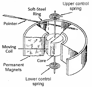
Permanent Magnet Moving Coil or PMMC Instruments consists of following components:
- Moving Coil
- Magnet System
- Control Spring
- Damping
- Pointer and Scale
Moving Coil:
The moving coil made up of copper is wound with many turns on the rectangular Aluminum former. This Aluminum former is pivoted on the jeweled bearing. The coil can move freely in the magnetic field produced by the Permanent Magnet System. In case of PMMC voltmeters, coil is generally wound on metallic frame to have the required electromagnetic damping. But in case of Ammeter, coils are wound on nonmagnetic former because coil turns are effectively shorted by Ammeter Shunt. Thus, we observe that in PMMC instruments, coil itself provides the electromagnetic damping.
Magnet System:
Simple U-shaped permanent magnet made of Alcomax or Alnico is widely use in PMMC instruments. Theses magnets have high coercive force and can produce field of the order of 0.1 to 1 Wb/m2. A soft iron end cylinder is bored in between the poles to make the field radial and uniform. In addition, this soft iron also reduced the reluctance of the air path between the poles and hence increases the magnetic field strength.
Control Spring:
The controlling torque in PMMC Instruments is provided by two control spring mounted on the jewel bearing. Theses control springs are phosphor bronze hair spring either helical or spiral, coiled in opposite direction. Control Spring also serves to lead current in and out of the moving coil.
Damping:
Damping torque in PMMC instruments are produced by the movement of Aluminum former in the magnetic field of Permanent Magnet. Due to movement of Aluminum former an eddy current is developed on the former which produces a damping torque.
Pointer and Scale:
The pointer is carried by the spindle and moves over a graduated scale. The pointer is of light weight construction and has a section over the scale twisted to form a fine blade. This helps in reducing the Parallax Error in reading the scale. In many instruments this parallax error can be further reduced by careful alignment of pointer blade and its reflection in the mirror adjacent to scale.
Torque Equation for PMMC Instruments:
The deflecting torque equation for Permanent Magnet Moving Coil or PMMC Instruments is given as
Deflecting Torque Ƭd = NBLdI = GI
Where G = a constant = NBLd
Where N = Number of turns in the moving coil
B = magnetic flux density between the magnetic poles
L = Length of moving coil
d = Breadth of moving coil
As the controlling torque is provided by the spring, therefore
Ƭc = KƟ
Where K = Spring constant
Ɵ = Angular movement of coil
At steady state condition, deflecting and controlling torque shall be equal,
Ƭd = Ƭc
⇒ GI = KƟ
⇒ Ɵ = (G / K)I ……………………(1)
Thus from the above equation (1), we observe that deflection in Permanent Magnet Moving Coil or PMMC Instruments is directly proportional to the current flowing in the moving coil. Because of this the meter scale of such instrument for the measurement of current / voltage is linear.
Moving-iron instruments
Construction and basic principle operation
Moving-iron instruments are generally used to measure alternating voltages and currents. In moving-iron instruments the movable system consists of one or more pieces of specially-shaped soft iron, which are so pivoted as to be acted upon by the magnetic field produced by the current in coil.
Analog ammeter and voltmeter designed to measure a.c. Current and a.c. Voltage
There are two general types of moving-iron instruments namely:
- Repulsion (or double iron) type (figure 1)
- Attraction (or single-iron) type (figure 2)
The brief description of different components of a moving-iron instrument is given below:
- Moving element: a small piece of soft iron in the form of a vane or rod.
- Coil: to produce the magnetic field due to current flowing through it and also to magnetize the iron pieces.
- In repulsion type, a fixed vane or rod is also used and magnetized with the same polarity.
- Control torque is provided by spring or weight (gravity).
- Damping torque is normally pneumatic, the damping device consisting of an air chamber and a moving vane attached to the instrument spindle.
- Deflecting torque produces a movement on an aluminum pointer over a graduated scale.
How it works?
The deflecting torque in any moving-iron instrument is due to forces on a small piece of magnetically ‘soft’ iron that is magnetized by a coil carrying the operating current. In repulsion type moving–iron instrument consists of two cylindrical soft iron vanes mounted within a fixed current-carrying coil.
One iron vane is held fixed to the coil frame and other is free to rotate, carrying with it the pointer shaft. Two irons lie in the magnetic field produced by the coil that consists of only few turns if the instrument is an ammeter or of many turns if the instrument is a voltmeter.
Current in the coil induces both vanes to become magnetized and repulsion between the similarly magnetized vanes produces a proportional rotation
The deflecting torque is proportional to the square of the current in the coil, making the instrument reading is a true ‘RMS’ quantity. Rotation is opposed by a hairspring that produces the restoring torque. Only the fixed coil carries load current, and it is constructed so as to withstand high transient current.
Moving iron instruments having scales that are nonlinear and somewhat crowded in the lower range of calibration.
Measurement of Electric Voltage and Current
- Moving iron instruments are used as Voltmeter and Ammeter only.
- Both can work on AC as well as on DC.
Ammeter
- Instrument used to measure current in the circuit.
- Always connected in series with the circuit and carries the current to be measured.
- This current flowing through the coil produces the desired deflecting torque.
- It should have low resistance as it is to be connected in series.
Voltmeter
- Instrument used to measure voltage between two points in a circuit.
- Always connected in parallel.
- Current flowing through the operating coil of the meter produces deflecting torque.
- It should have high resistance. Thus a high resistance of order of kilo ohms is connected in series with the coil of the instrument.
Ranges of Ammeter and Voltmeter
- For a given moving-iron instrument the ampere-turns necessary to produce full-scale deflection are constant.
- One can alter the range of ammeters by providing a shunt coil with the moving coil.
- Voltmeter range may be altered connecting a resistance in series with the coil. Hence the same coil winding specification may be employed for a number of ranges.
Advantages
- The instruments are suitable for use in AC and DC circuits.
- The instruments are robust, owing to the simple construction of the moving parts.
- The stationary parts of the instruments are also simple.
- Instrument is low cost compared to moving coil instrument.
- Torque/weight ratio is high, thus less frictional error.
Errors
- Error due to variation in temperature.
- Error due to friction is quite small as torque-weight ratio is high in moving coil instruments.
- Stray fields cause relatively low values of magnetizing force produced by the coil. Efficient magnetic screening is essential to reduce this effect.
- Error due to variation of frequency causes change of reactance of the coil and also changes the eddy currents induced in neighbouring metal.
- Deflecting torque is not exactly proportional to the square of the current due to non-linear characteristics of iron material.
INDUCTION TYPE WATTMETER, WATT-HOUR METER, AND DYNAMOMETER TYPE POWER FACTOR METER
Induction Type Wattmeter
These types of watt-meters operate on the same working principle on which the induction type ammeter and voltmeter operates. These instruments can only be used on ac supply while dynamo-meter type watt meters can be used on either ac or dc supply system. Induction type watt-meters are useful only when the supply and frequency remain constant. Since both the coils i.e. current coil and pressure coils are necessary in such instrument, it is not essential to use shaded pole principle. Because for producing a deflecting torque, two fluxes are essential with suitable phase angle and it would be available from these two coils.
Construction
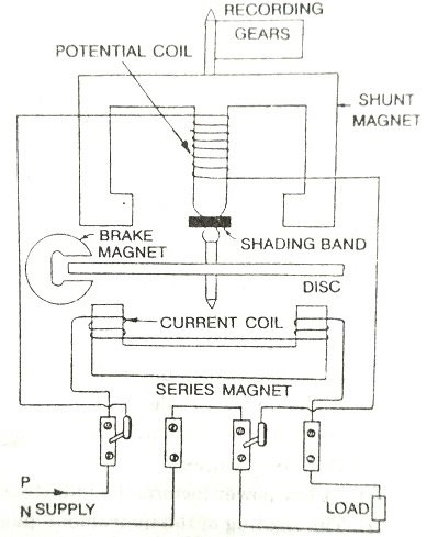
A watt-meter has two laminated electromagnet, one of which is excited by load current or definite fraction of it, and is connected in series with the circuit, known as series magnet and the other is excited by the current proportional to the applied voltage or fraction of it and is always connected across the supply, known as shunt magnet. An aluminum disc is so mounted so that it cuts the fluxes produced by both the magnets. As a result of which, two e.m.f are produced which induces two eddy currents in the disc. C - Magnet is used to provide necessary damping torque to the pointer, to damp out the oscillations. Deflecting torque is produced due to interaction of these eddy currents and the inducing flux. Copper shading bands are provided either on central limb or on the outer limb of the shunt magnet, and can be so adjusted as to make the resultant flux in the shunt magnet lag behind the applied voltage by 90. Both the watt-meters are provided with spiral springs A and B, for producing controlling torque to counter balance the deflecting torque. In Fig. 13.2 the spiral spring and damping magnet is omitted for simplicity. The scale of such type instruments is quite uniform and extends over an angle of 300. Currents up to 100 A can be handled by these watt-meters directly whereas beyond this current transformers are used. Two types of induction type watt meters are available. Line diagrams of both of the types are detailed in Fig. 13.1 and 13.2.
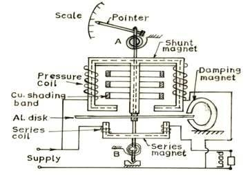
Fig. Induction type wattmeter
In the form of the instrument shown in Fig. 13.1, two pressure coils are connected in series in such a way that both of them send flux through the central limb. The series magnet also carries two small current coils connected in series and wound so that they magnetized their respective cores in the same direction. Correct phase displacement between the fluxes produced by series and shunt magnet is obtained by the adjustment of copper shading band on the central limb.
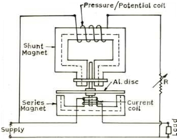
Fig. Induction type wattmeter
In Fig. 13.2, there is only one pressure and one current coil. Two projecting poles of shunt magnet are surrounded by a copper shading band whose position can be adjusted for correcting the phase of the flux of this magnet with the applied voltage. The pressure coil circuit of induction type instrument is made as inductive as possible so that the flux of the shunt magnet may lag nearly by 90 behind the applied voltage.
Advantages
The advantages of induction watt meters are the same as those of induction ammeters long scale, freedom from effects of stray field, and have effective damping torque.
Disadvantages
Following are the disadvantage of the induction type instruments:
a) Change in temperature causes variation in the resistance of the moving element, affects the eddy currents therein, and so the operating torque. The error due to this is in part offset by a balancing effect due to change in temperature of the windings.
b) Change in frequency from that of the calibration value causes variations in both the reactance of the voltage coil circuit, which is highly inductive, and also in the amount of compensation from the phase compensating circuit. Within the limits of frequency variation met within practice on the mains, this last error in not important.
Induction Type Single Phase Watt Hour Meter
A watt hour meter is used to sum up the total energy consumed by a consumer during a period so that it can be charged for the actual energy consumed. The working principle, theory and advantage / disadvantages are almost similar to single phase watt meter. The construction of single-phase watt hour meter is also almost similar to single phase induction type watt meter as discussed above. The pointer and spiral springs are replaced by wheel-train mechanism for summing up of total energy consumed whereas the damping magnet is replaced by braking magnet. The construction of this type of watt hour meter is shown in Fig.
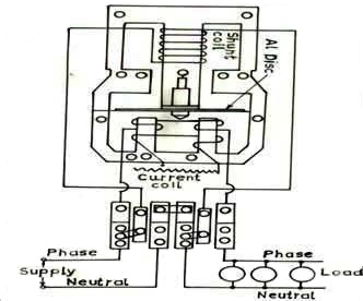
Fig.Induction type energy meter
The brake magnet and recording wheel-train being omitted for clear understanding of the diagram. The description of registering mechanism and braking system is detailed below.
Registering or counting system
The registering or counting system essentially consists of gear train, driven either by worm or pinion gear on the disc shaft, which turns pointers that indicate on dials the number of times the disc has turned. The energy meter thus determines and adds together or integrates all the instantaneous power values so that total energy used over a period is thus known. Therefore, this type of meter is also called an integrating meter.
Braking system
Braking of the disk is provided by a small permanent magnet, located diametrically opposite to the alternating current magnets. The disk moves between the magnet�s gaps. The movement of rotating disc through the magnetic field crossing the air gap sets up eddy currents in the disc that reacts with the magnetic field and exerts a braking torque. By changing the position of the brake magnet or diverting some of the flux therefore, the speed of the rotating disc can be controlled. Creep error can be rectified by drilling a small hole in the aluminum disc passing through the magnetic flux of braking magnet.
Errors and Adjustment in Induction Type Instruments
Phase and speed error
It is necessary that the energy meter should give correct reading on all power factors, which is only possible when the field set up by shunt magnet flux lags behind the applied voltage by 90. Ordinarily the flux set up by shunt magnet does not lag behind the applied voltage exactly by 90 because of winding resistance and iron losses. The flux due to shunt magnet is made to lag behind applied voltage by 90 with the help of copper shading band provided on the central limb. An error due to incorrect adjustment of shading band will be evident when the meter is tested on a load of power factor less than unity.
An error on the fast side under these conditions can be eliminated by bringing the shading band nearer to the disc and vice versa. An error in the speed of the meter when tested on non-inductive load can be eliminated by adjustment of the position of the brake magnet. Movement of the brake magnet in the direction of the spindle will reduce the braking torque and vice versa. Speed of disc is directly proportional to the distance between the disc and brake magnet.
Friction compensation
The two shading bands embrace the flux contained in the two outer limbs of the shunt electromagnet, and thus eddy current are induced in them which cause a phase displacement between the enclosed flux and main gap flux. As a result, a small driving torque is exerted on the disc, this torque being adjusted, by variation of the position of these bands, to compensate for frictional torque in the instrument.
In some energy meter, it is observed that the disc continue to rotate even when the load on the energy meter is zero and potential coil is in excited condition. This defect is known as creeping and is prevented by cutting two holes or slots in the disc on opposite sides of the spindle. The disc tends to remain stationary when one of the holes comes under one of pole of the shunt magnet. In some cases, a small piece of iron wire is attached to the edge of the disc. The force of attraction of the brake magnet upon this wire is sufficient to prevent continuous rotation of the disc under no load condition.
Temperature and frequency errors
The error due to variation in temperature is very small. Since the various effects due to change in temperature tends to neutralize each other on unity power factor if not on low power factor (lagging). Since the meters are used normally on fixed frequency and hence these can be adjusted to have a minimum error at declared supply frequency which is normally 50 cycles / second.
Single Phase Dynamo-meter Type Power Factor Meter
The power factor meter is used to indicate the instantaneous power factor of the consumer. It consists of two fixed coils CC connected in series carrying the load current (or a definite fraction of it) and two identical moving coils P1 & P2 wound with a fine copper wire, fixed at right angle to each other and pivoted on the same spindle. The pressure coils P1 and P2 move together and carry a pointer, which indicates the power factor of the circuit directly on the scale.
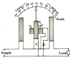
Fig. Dynamometer type power factor meter
The pressure coil P1 is connected across the supply through a non-inductive resistance R and pressure P2 is connected across the supply through a highly inductive choke coil of inductance L. The value of non-inductive resistance R and inductance L are so chosen that for the normal frequency, the current in the two pressure coil P1 and P2 is same. Thus, these coils P1 and P2 produce equally strong magnetic field displaced by 900 in space as well as in the phase. For measurement of power factor on high voltage system, the current and pressure coils of the instrument may be connected to the main circuit through current and potential transformer respectively.
Theory
While measuring power factor of an installation, there may be three possibilities of installations power factor, which are described here:
(a) Power Factor is Unity: When the circuit is switched on, the current in the potential coil P1 will be in phase with current in coils CC, whereas the current in pressure coil P2 will lag 900 behind the voltage or behind the current in the circuit coli CC. Thus, pressure coil P1 will experience a turning moment so its plane will come in a position parallel to a plane of a current coil CC. The average torque on coil P2 will be zero but being mechanically coupled to coil P1, it will follow the rotation of coil P1. Hence the pointer will in the centre of the calibrated scale and it will show the power factor as unity. The position of coil P1 is shown in Fig. 13.4 and it will maintain the reading till the load current is in phase with the voltage.
(b) When Power Factor is Zero (lagging): In this situation, the current flowing in the pressure coil P2 will be in phase with load current flowing in the fixed current coil CC, both lagging behind the applied circuit voltage by 900 and current in pressure coil P1 will lead the load current in current coil CC by 900. Thus only pressure coil P2 will experience a turning moment so its plane will come in a position parallel to the plane of current coils CC. At this instant, the pointer will indicate zero power factor lagging.
(c) When Power Factor Zero (leading): When the current flowing in fixed coils CC leads the applied voltage by 90 and, therefore, the field of pressure coils P1 by 90 and that of coil P2 by 180. Hence the polarity of field in current coils is the reverse of that considered above. At this instant, the pointer will indicate the power factor as zero leading on the other half of the scale.
For an intermediate power factor, the moving system takes up intermediate position and the pointer makes an angle of (90 with the axis of the fixed coils where the phase angle between load current is and applied voltage of the load circuit.
INDUCTION TYPE SINGLE PHASE ENERGY METER:
Induction type instruments are used for a. c. Measurements. The induction principle find its widest application as an energy meter. Induction type energy meter used invariably to measure the energy consumed in any a.c. Circuits in a prescribed period where supply voltage and frequency are constant. Energy meter is an integrating instrument which measures the total quantity of electrical energy supplied to the circuit in given period.
Principle:
The basic principle of induction type energy meter is electromagnetic induction. When alternating current flow though two suitably located coils produces rotating magnetic field which is cut by the metallic disc suspended near to the coils thus emf induce in the disc which is circulates eddy current in it. By interaction of rotating magnetic field and eddy currents, torque is developed and cause the disc rotate.
Construction:
An induction type single phase energy meter, as show in fig has following main parts of the operating mechanism.
- Driving system.
- Moving system.
- Breaking system.
- Recording mechanism.
1.Driving system.
It consists of two electromagnets, called “shunt” magnet and “series” magnet,
Series magnet: it consists of a number of U-shaped laminations of silicon steel together to form a core. A coil of thick wire having a few turns is wounded in both legs of U-shaped magnet. The coil is known is current coil which is connected series with load. Produce the magnetic field proportional and in phase with line current I.
Shunt magnet: it consists of number of M-shaped laminations of silicon steel assembled together to form a core.A coil of thin wire having large number of turn in wound on central limb of the magnet. This coil is connected across the load. Thus it is excited by current proportional to the supply voltage and known is potential coil.
2.Moving system.
The moving system essentially consists of a light rotating aluminum disk mounted on a vertical spindle or shaft. The shaft that supports the aluminum disk is connected by a gear arrangement to the clock mechanism on the front of the meter to provide information that consumed energy by the load.
The time varying (sinusoidal) fluxes produced by shunt and series magnet induce eddy currents in the aluminum disc.
The interaction between these two magnetic fields and eddy currents set up a driving torque in the disc.
The number of rotations of the disk is therefore proportional to the energy consumed by the load in a certain time interval and is commonly measured in kilowatt-hours (kWh).
3.Breaking system.
Damping of the disk is provided by a small permanent magnet, located diametrically opposite to the a.c magnets. The disk passes between the magnet gaps. The movement of rotating disc through the magnetic field crossing the air gap sets up eddy currents in the disc that reacts with the magnetic field and exerts a braking torque.
By changing the position of the brake magnet or diverting some of the flux there form, the speed of the rotating disc can be controlled.
4.Recording mechanism.
The function of recording or registering mechanism is to record continuously a number on the dial which is proportional to the revolutions made by the moving system. The no of revolution on the disc is a measured the electrical energy passing though the meter.
Working of Single phase energy meter:
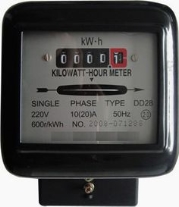
When the energy meter is connected in circuit, the current coil carries the load current and pressure coil carries the current proportional to the supply voltage. The magnetic field produced by series magnetic in phase with the line current and magnetic field produced by shunt magnet is in quadrature with the applied voltage.thus, a phase difference exists between the fluxes produce by the two coils. This setup rotating magnetic field which interacts with disc and produce a driving torque and thus, disc starts rotating.the number of revolutions made by the disc depend upon energy passing though the meter. The spindle geared to the recording mechanism so that energy consumed in the circuit is directly registered in kWh.
the speed of the disc is adjusted by adjusting the position of braking magnet. Example, if the energy meter registers less energy than the energy actual consumed in the circuit. Then the speed of disc has to be increased which is obtained by sifting the braking magnet nearer to the centre of the disc vice -versa.
Meter Constant, K = No. Of revolutions
Energy supplied in kWh
Voltage Multiplier
When a meter is to be used as a voltmeter, a series resistor is used to limit the current to the specified FSD with the maximum applied voltage that you want to measure. This is a very easy calculation to make, since it involves nothing more advanced than Ohm's law.
For example, we want to measure the voltage from a power supply, and have a 1mA meter movement available, having a coil resistance of 200 ohms. If the maximum supply voltage is 50V, then the meter should read from 0-50V. The total resistance needed will limit the current through the meter to 1mA with 50V applied, so ...
R total = V / I = 50 / 1mA = 50kΩ
Since the meter has 200 ohms resistance, the series resistor will be ...
R mult = 50k - 200 ohms = 49,800 ohms
This is not a standard value, so will need to be made up using series / parallel resistors. Of course, one can always cheat and use a 47k resistor in series with a 5k pot, thus enabling the meter to be calibrated to a high accuracy. We do need to check the resistor power rating, because it is easy to forget that the multiplier resistor can dissipate a significant power - especially at high voltages. The resistor power is given by ...
P = I² × R = 1mA² × 47000 = 53mW
The power dissipation is well within limits for even the lowest power resistor. Be very careful when determining the multiplier resistance for high voltages. Although the power rating may be quite low, the gradient voltage across the resistor may exceed its ratings. It is imperative that resistors are not operated above the maximum rated voltage for the particular type of resistor. This specification is not often given, so it is best to assume the worst case, and limit the voltage across any 0.5W resistor to no more than around 150V - less for 0.25W resistors.
It is generally preferable to use the most sensitive meter you can get within your price range, so in this case, a 50µA movement would be a far better proposition. Less current is drawn from the measured voltage source, so there is less loading on potentially sensitive circuits. This was always a problem when measuring voltages in valve amplifiers, because typical cheap analogue multimeters often used relatively high current movements, and this loaded the voltage under test giving incorrect readings. Analogue multimeters usually had a rating of 'Ohms/Volt' - the 1mA movement described above uses 50k total resistance to measure up to 50V, so that would be rated at 1kΩ/ Volt.
The better multimeters of yesteryear were rated at a minimum of 20kΩ/V up to 100kΩ/Volt (the Sanwa meter mentioned above was 500kΩ/Volt!). To obtain even higher measurement impedance, the better equipped workshops and laboratories back then used a VTVM (Vacuum Tube Volt Meter), offering an input impedance of around 10-100MΩ. These were followed by FET input transistorised units, and finally displaced by digital multimeters. Despite their popularity, digital multimeters are still very bad at some measurements, and are often not as accurate as we tend to think they are.
Using a 50µA movement, the multiplier resistor needs to be ...
R mult = V / I = 50 / 50µA = 1MΩ - 3500 (meter resistance) = 996,500 ohms
... Which works out to be 20kΩ/ Volt. Again, this resistance can be made up by series connection of different values, but a 1MΩ resistor is perfectly ok. The error is much smaller than the tolerance of the resistor or the meter movement, at 0.35%. If you need greater accuracy you will need to use a trimpot with a series resistor as described above for the 1mA movement.
That's all there is to multipliers - as stated in the beginning of this section, they are very easy to work out.
Current Shunt
The situation is a little more complex when calculating a shunt for current measurement. Not so much because the calculations are difficult, but because you will be working with very low resistance values. It is also important to ensure that the meter is connected directly to the shunt - even a small length of wire in series may make readings uselessly inaccurate. The schematic diagram below shows not only the electrical connection, but also the physical connection to the shunt.
In most cases, it is easier to calculate (or measure) the voltage across the meter movement for FSD. If you don't know the resistance, it can be measured with a digital multimeter. The current from most digital multimeters is low enough not to cause damage to the meter, but the pointer may swing rather violently. Connect with reverse polarity to minimise the risk of bending the pointer.
Unless you are measuring low currents (less than 1A or so), the shunt resistance can be worked out using Ohm's law, and will be accurate enough for most purposes. This is covered below.
Assuming a 1mA movement with an internal resistance of 200 ohms, as an example we wish to measure 5A. This means that 4.999A must pass through the shunt, with the remaining 1mA passed by the meter movement. The shunt resistance can be found with the following formula ...
Rs = Rm / ( Is / Im) where Rs is the shunt resistance, Rm is the meter resistance, Is = shunt current, Im = meter current
So for our example,
Rs = 200 / ( 5A / 1mA ) = 0.04Ω
If we use only Ohm's law (having determined that there will be 200mV across the movement - 1mA and 200 ohms), the shunt can be calculated as ...
Rs = Vm / I where Rs is shunt resistance, Vm is meter voltage at FSD, and I is the current
Rs = 0.2 / 5 = 0.04Ω
This method will work to within 1% accuracy provided the measured maximum current is more than 100 times the meter current. One thing we have to be careful of with shunts is that the voltage 'lost' across them (known as the 'burden' is not excessive. This will reduce the voltage supplied to the load, and can result in significant errors, especially at low currents. For example, if we only need to measure 1mA, we can use the meter directly, but we lose 200mV across the meter. In the case of the 0.04 ohm shunt calculated above, we lose ...
V = R × I = 0.04 × 5A = 200mV
... Exactly the same voltage loss! It's not a great deal, but can be critical in some exacting tests or at very low voltages. 200mV is almost nothing with a 50V supply (0.4%), but is very significant if the applied voltage is only 1V (a full 20% loss). The voltage drop can be reduced slightly by using a more sensitive movement. For a 50µA movement with 3,500 ohms resistance, the loss is ...
V = R × I = 3500 × 50µA = 175mV
There's not much of a gain, but there are also not many alternatives. DC current measurement will always lose some voltage, so it is important that the voltmeter is always connected after the ammeter, so that the 'lost' voltage is taken into consideration. Where extremely low voltage drop is important, one must resort to amplification. An opamp can be used to amplify the voltage across a much smaller value shunt, but at the expense of circuit complexity and temperature drift. Digital panel meters are often (but not always) better than analogue movements for current measurements.
The idea of a shunt is all well and good, but where does one obtain an 0.04 ohm resistor? It can be made up of a number of wirewound or metal film resistors in parallel, or a dedicated shunt may be available. Obtaining high accuracy at such low resistances is very difficult though, and shunts are generally cut, machined or filed to remove small amounts of metal until the exact value needed is achieved. The shunt must be made from metal having a low temperature coefficient of resistance to prevent the reading being affected by changes in temperature - either ambient, or caused by the load current heating the shunt. Common shunt materials are Constantan (copper-nickel, aka Eureka), manganin (copper, manganese, nickel) and nichrome (nickel-chrome).
There is an easier way to calibrate a shunt, as shown in Figure 5. The voltage drop will be a bit higher than it should be, but you only need a few millivolts extra to be able to use the technique.
Now it is possible to use 2 × 0.1 ohm resistors in parallel, giving 0.05 ohm. The voltage drop at 5A will be 250mV, but you have the advantage of being able to use standard tolerance resistors, which can represent a significant saving. The power is only 1.25W at full current, so a pair of 5W resistors will barely get warm. The trimpot can be adjusted to give an accurate reading, without having to resort to close tolerance resistors with impossible values. As an example for the above 5A meter, we could use a 100 ohm trimpot in series with the meter. The value is not particularly important, but needs to be within a sensible range.
What is 'sensible' in this context? Easy. We already know that the meter needs 200mV for full scale and that we will get 250mV across a 0.05Ω shunt, so we need a resistance that will drop 50mV at 1mA.
R = V / I = 0.05 / 0.001 = 50 ohms
Since we are using a pot, it is advisable to centre the wiper under ideal conditions to give maximum adjustment range (to allow for worst case tolerance), so a 100 ohm pot is ideal.
IC Current Monitors
There is an alternative method for measuring DC (or AC) current with almost no loss at all. ICs are available that use a thick conductor and a fully isolated Hall-effect sensor to measure the magnetic field generated as current passes through the conductor. An example is the Allegro Microsystems ACS770LCB-050B, a bidirectional Hall-effect sensor that can handle up to ±50A, providing ±40mV/A output, centred on the quiescent output voltage of 2.5V. A unidirectional (DC only) version is also available.
With an output voltage of ±2V (referred to 2.5V), the output voltage range is from 500mV to 4.5V over the full range. While these are very useful devices, they are not inexpensive, and require additional electronics to obtain a usable output. If you need to sense low current, then be prepared for a fairly noisy output signal. Some of the noise can be removed with a filter, but that further increases complexity.
The device mentioned is not the only one of its type, but is representative of those you can use. Another is the Honeywell CSLA2CD as described in Project 139. This is a more versatile device (which is also likely to be quieter), but they are not inexpensive, at around AU$40-50 each depending on supplier. Even the Allegro IC costs a bit more than you might expect, at around AU$13.00 each (one off price). There are many other current sensor ICs available, but this is not the place to go into great detail.
Expanded Scale Voltmeter
You may have seen expanded scale voltmeters used in cars to monitor the battery voltage. Since no-one is interested if the battery measures less than 10V (it's dead flat!), and it should never exceed 15V, a meter that measures from 10V to 15V is nice to have. This is surprisingly easy to do, and although absolute accuracy is not wonderful in a simple application, it is more than acceptable for the purpose.
By using a zener diode, a base reference is established, and the meter only measures between the reference and actual battery voltage. We will use a 1mA movement again (as shown above). This scheme can be adapted for any desired voltage. The voltmeter only needs to measure the voltage drop across the zener feed resistor, which is needed to ensure that an acceptable current flow in the zener diode. The 1mA drawn by the meter is not enough to obtain a stable voltage.
The multiplier is worked out in the same way as before ...
R total = V / I = 5 / 1mA = 5kΩ
Because the multiplier resistance is much smaller than before, we must take the meter resistance of 200 ohms into consideration.
R mult = R total - R meter = 5000 - 200 = 4800Ω
A 4.7k resistor will introduce a small error, but a 3.9k resistor in series with a 2k trimpot will allow the meter to be set very accurately. The zener feed resistor value is not critical, but should ensure that the zener current is between 10% and 50% of the maximum for the device. Assuming a 10V 1W zener, the maximum current is ...
Iz max = P / V = 1 / 10 = 0.1 = 100mA
Using Ohm's law, we get a resistance value of 100 ohms for a zener current of 50mA at 15V. This will fall as the voltage is reduced, but extreme accuracy at 10V is not possible, so this arrangement should work fine.
Digital Panel Meters
DPMs (Digital Panel Meters) are often very attractive, not just for their perceived accuracy, but because they can often be obtained for the same or less than a good analogue meter movement. They also have better linearity than most of the cheap movements, so there are some real benefits. Most are available with a quoted sensitivity of 200mV (199.9mV full scale), so are comparable to analogue meters in terms of voltage drop for current measurement. They have the great advantage of a (typical) 100MΩ input impedance, so voltage loading is extremely low. In addition, they will measure positive and negative voltage or current - this is available with a centre zero analogue meter, but they are hard to find.
Most DPMs are classified as 3½ digit, meaning that they display up to a maximum of 199.9mV. The most significant digit can only be blank or 1, and the other 'half' is used to display a negative sign to indicate that the input is negative with respect to the common or ground terminal. This often means that much of the range is wasted if you want to display a range other than 0-1999. Note that most DPMs do not automatically select the decimal point, and there are extra pins to allow the user to select the position of the decimal point (or to ignore it completely). Analogue meters have no such limitation, because the scale can be calibrated with any units you wish, and covering any range.
Digital Voltmeter
Measuring voltage with a DPM is easy - most even come with instructions that show you how to do it. You do need to be careful to ensure that possibly destructive voltages cannot be coupled to the inputs. Like all ICs, the ADC (Analogue to Digital Converter) used is sensitive to excess voltage, and the IC can be destroyed. Although the following circuit uses a ½-wave rectifier, full-wave rectification is better (using a diode bridge). However, this may mean that a simple 'off-line' power supply cannot be used for the meter IC. The voltage divider should be re-calculated if a full wave bridge is used, because the ratio of peak to average is 1.58 (full-wave rectified 230V has an average value of 205.7V).
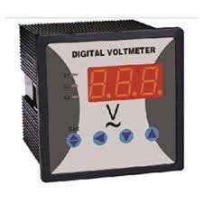
This is designed to monitor the output from my workshop Variac (variable transformer). To ensure an adequate voltage rating for R div1 4 × 100k 1W resistors were used in series parallel, maintaining the peak voltage across each to 163V (the peak of 230V AC is 325V). 1W resistors were not used for their power rating, but to have a large resistance section, maintaining a relatively low voltage gradient across the resistor surface. Because the Variac can deliver 0-260V, the voltage to the DPM will be 0-26mV, and this is a half-wave rectified signal. The meter averages the applied voltage. Note that the 5V supply must be isolated, because it could have the full mains potential on all terminals if the active (live) and neutral conductors are ever swapped around. This is critically important - the entire circuit (including power supply) must be considered as being at mains potential.
To obtain the (approximate) average value of ½ wave rectified AC, you divide the peak voltage by 3.12. Based on this and for an average signal of 23mV, the average input voltage is 104V (325 / 3.12), so the voltage divider needs a ratio of ...
Vdiv = Vin / Vout = 104 / 23mV = 4522
For all reasonably high voltages, the division ratio is so high as to cause significant errors even with 1% resistors, and the use of a trimpot to adjust the value is strongly recommended. Since I used 100k for Rdiv1 (because I had 100k/1W resistors handy), the parallel combination of Rdiv2 and VR1 needs to be slightly more than ...
Rdiv2 = Rdiv1 / ( Vdiv - 1 ) ≈ 22 ohms (actually 22.12 ohms, but all values are approximate because using fixed resistors is not sensible)
50 ohms (as used) allows VR1 to be roughly centred, and there is plenty of adjustment range. Needless to say, exactly the same technique can be applied to an analogue meter as well, but you need to allow for the much lower input impedance (perhaps 100 ohms rather than 100M for the DPM that I used). As it turns out, with an average voltage of 104V and a resistance of 100k, the current is 1.04mA, so the meter can be driven directly (leaving out Rdiv2 and VR1). You will need to readjust the resistance though, because the (in)accuracy is 4% - much better results can be obtained, but most analogue meter movements will have a greater error than that built-in. A pot is highly recommended because the AC waveform is not very predictable, and large errors may result from waveform distortion. This also applies if the mains is full-wave rectified. The divider network is still usable as shown, but Rdiv2 should be reduced to 39 ohms.
For a more conventional application, Figure 8 shows a basic 0-50V digital meter. The resistor values are fixed in this case. Because of the high input impedance of the DPM, we can use 1M for the upper divider resistor. The division ratio is determined the same way as before ...
Vdiv = Vin / Vout = 50 / 50mV = 1000
Rdiv2 = Rdiv1 / Vdiv = 1M / ( 1000 - 1 ) = 999Ω (Use 1k)
Using a 1k resistor is not an issue, because the resistor tolerance is much greater than the 1 ohm difference in the calculated values. The same result can be achieved using 10k and 10 ohms (or 100k and 100 ohms), but there is not normally any need to aim for very low impedances. You may find that the meter displays 'rubbish' values in the least significant digit - this means that noise is being picked up. Use of a lower impedance divider may reduce that, or you can place a cap (100nF or so) in parallel with RDiv2. If you need the circuit to be particularly accurate, then you will need to use 0.1% resistors or add a pot so it can be adjusted. A pot is a lot cheaper and easier to get than 0.1% resistors, especially if you end up with odd values.
Digital Ammeter
DPMs have a benefit as ammeters, but usually only if you don't need the full scale. Since the typical sensitivity is 200mV, by using only a part of the maximum reading, you can use lower shunt resistances than with analogue movements.
The procedure for calculating the shunt is exactly the same as for an analogue meter, except that there is no meter current. You simply need to calculate the shunt based on the meter voltage for the desired current reading ...
Rs = Vs / I = 50mV / 5A = 0.01Ω
This gives a much lower shunt resistance, because only 50mV is needed at the meter input. The circuit shown will work up to 20A (19.99A to be exact) with the same 0.01Ω shunt resistor. Note that the input is shown on the negative supply, with the +ve input going to the positive supply via the load. If the input and power supply -ve terminals are not at the same potential, then the supply for the meter must be floating - it cannot be grounded. If you wanted to monitor the current in the positive supply lead for example, you need a floating auxiliary supply.
