Unit-1
Two Dimensional Force Systems
Newton’s first law states that, if a body is at rest or moving at a constant speed in a straight line, it will remain at rest or keep moving in a straight line at constant speed unless it is acted upon by a force. This postulate is known as the law of inertia. The law of inertia was first formulated by Galileo Galilei for horizontal motion on Earth and was later generalized by René Descartes. Before Galileo it had been thought that all horizontal motion required a direct cause, but Galileo deduced from his experiments that a body in motion would remain in motion unless a force (such as friction) caused it to come to rest.
Newton’s second law is a quantitative description of the changes that a force can produce on the motion of a body. It states that the time rate of change of the momentum of a body is equal in both magnitude and direction to the force imposed on it. The momentum of a body is equal to the product of its mass and its velocity. Momentum, like velocity, is a vector quantity, having both magnitude and direction. A force applied to a body can change the magnitude of the momentum, or its direction, or both. Newton’s second law is one of the most important in all of physics. For a body whose mass m is constant, it can be written in the form F = ma, where F (force) and a (acceleration) are both vector quantities. If a body has net force acting on it, it is accelerated in accordance with the equation. Conversely, if a body is not accelerated, there is no net force acting on it.
Newton’s third law states that when two bodies interact, they apply forces to one another that are equal in magnitude and opposite in direction. The third law is also known as the law of action and reaction. This law is important in analysing problems of static equilibrium, where all forces are balanced, but it also applies to bodies in uniform or accelerated motion. The forces it describes are real ones, not mere bookkeeping devices. For example, a book resting on a table applies a downward force equal to its weight on the table. According to the third law, the table applies an equal and opposite force to the book. This force occurs because the weight of the book causes the table to deform slightly so that it pushes back on the book like a coiled spring.
The state of the rigid body will not change if force acting on a body is replaced by another force of same magnitude & direction acting anywhere on the body along the line of action of replaced force. The value of force will not change along the Line of action of force within the body.

Resultant Force:
When many forces are acting, the overall effect can be considered in a single force. This single force is called resultant force and the given individual forces are called component forces.
Methods for the resultant force
Though there are many methods for finding out the resultant force of a number of given forces, yet the following are important from the subject point of view:
- Analytical method.
- Method of resolution.
Analytical method includes the Parallelogram law of Vectors which is described as “If two forces, acting simultaneously on a particle, be shown by two sides of parallelogram, then the resultant will be the diagonal between these sides of parallelogram.”
Mathematically, resultant force,

Where R is the resultant force, A and B are component vectors and  is the angle between the two vectors, as shown below.
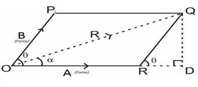
For finding the direction of resultant vector, we need to find the angle between A and R i.e.  .
.

The resultant of this force system is either a single force or a couple.
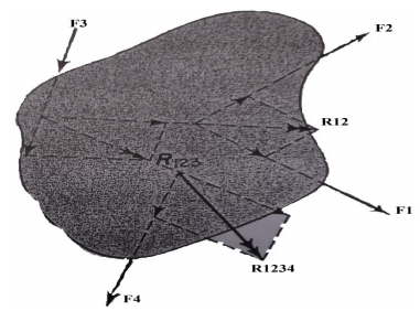
The resultant is a couple when the resultant of all but one of the forces of the system and the remaining force form a couple. To determine the resultant analytically, each force is resolved into rectangular components in the x and y directions.
1When the algebraic sum of the components in either the x or y direction, or both, is different from zero, the resultant is a force, and its magnitude can be determined from the following equations:
Rx=∑Fx
RY=∑FY
R=√ (RX2+RY2)
Tan-1Θx=RY/RX
The location of a point on the action line of the resultant is determined by the principle of moments.
𝑅𝑞 = ∑𝑀𝑂
Where q is the perpendicular distance from the moment axis through o to the resultant force R.The direction from O to R is determined from the sense of R and ∑ 𝑀𝑂
2. When the algebraic sum of the components of the forces is zero in two different directions, the resultant cannot be a single force but can be a couple in the plane of the forces. The magnitude of the moment of the couple and its sense of rotation can be determined as the algebraic sum of the moments of the forces of the system with respect to any point in the plane.
Note:- For the special case of a parallel coplanar force system with the x axis parallel to the forces R of the system y = 0 and the resultant if a force, is parallel to the x axis
Distributed force is any force where the point of application of the force is an area or a volume. This means that the "point of application" is not really a point at all. Though distributed forces are more difficult to analyse than point forces, distributed forces are quite common in real world systems so it is important to understand how to model them.
Distributed forces can be broken down into surface forces and body forces. Surface forces are distributed forces where the point of application is an area (a surface on the body). Body forces are forces where the point of application is a volume (the force is exerted on all molecules throughout the body). Below are some examples of surface and body forces.
Distributed forces are represented as a field of vectors. This is drawn as a number of discrete vectors along a line, over a surface, or over a volume, that are connected with a line or a surface as shown below.

This is a representation of a surface force in a 2D problem (A force distributed over a line). The magnitude is given in units of force per unit distance.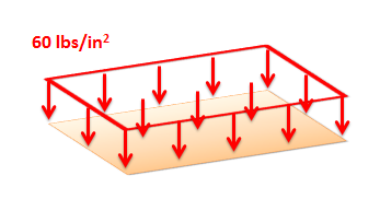
This is a representation of a surface force in a 3D problem (a force distributed over an area). The magnitude is given in units of force per unit area (also called a pressure).
Though these representations show a discrete number of individual vectors, there is actually a magnitude and direction at all points along the line, surface, or body. The individual vectors represent a sampling of these magnitudes and directions.
It is also important to realize that the magnitudes of distributed forces are given in force per unit distance, area, or volume. We must integrate the distributed force over its entire range to convert the force into the usual units of force.
Analysing Distributed Forces
For analysis purposes in statics and dynamics, we will usually substitute in a single point force that is statically equivalent to the distributed force in the problem. This single point force is called the equivalent point load and it will cause the same accelerations or reaction forces as the distributed force while simplifying the math. In the strength of materials context where the bodies are not rigid, this substitution will not work however as the distributed forces will not cause the same deformations and stresses as the point force.
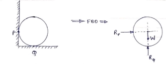
If a body is shown with all external forces acting on it so that the body is in equilibrium, such diagram is called as free body diagram. To draw the free body diagram, we have to remove all the restrictions like wall, floor, hinge, any other support and replace them by reactions which these support extents on the body.
Ex – 1) Draw FBD of a bar supported and loaded as shown below.

2) Draw FBD of sphere supported as shown below.
Equilibrium
- A body is said to be in equilibrium if the resultant of all forces acting on it is zero.
- When the resultant of all the forces acting on the particle is zero, then, the particle is in equilibrium.
- If the resultant force acting on a particle is zero (or if particle is in equilibrium state) the, particle will remain at rest condition if it is originally at rest; or particle will move with constant speed in a straight line if it is originally in motion.
Condition for Equilibrium: R = 0 {  }
}
∑M = 0
 Equilibrium of body subjected to two forces
P=Q, body is in equilibrium P=Q, but body is not in equilibrium
If an object is subjected to forces acting at two points, then body will be in equilibrium only when those two forces are equal & opposite.
Equilibrium equation.
• Apply the equations of equilibrium, Σ Fx = 0 and Σ Fy = 0.
• The forces are directed as positive for those along positive axis and vice-versa.
• If the resultant comes out to be negative value, it means that the direction needs to be reversed for that is already considered.
As we know, the sufficient case for stating equilibrium for a body under combination of forces is Σ F = 0.
For any three-dimensional force system, as shown in Fig. Below, we can resolve the forces into their respective i, j, k components, so that
Σ Fx i + Σ Fy j + Σ Fz k = 0
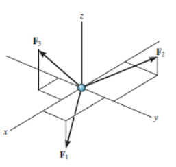
To satisfy this equation we require,
Σ Fx = 0
Σ Fy = 0
Σ Fz = 0
These three equations state that the algebraic sum of the components of all the forces acting on the particle along each of the coordinate axes must be zero. Using these equations mentioned we can solve for maximum three of the unknowns, shown by coordinate direction angles or magnitudes of forces shown on the particle’s free-body diagram.
For solving three dimensional problems we can use the following procedure.
Free Body Diagram:
• In any orientation, establish x and y axes.
• Then mark all the known and unknown forces in figure.
• Unknown forces are also assumed and plotted.
Equations of Equilibrium.
• Apply the equations of equilibrium, Σ Fx = 0, Σ Fy = 0 and Σ Fz = 0.
• Initially we can display as a Cartesian vector if it becomes to solve the problem regularly substitute these vectors into Σ F = 0 and then set the i, j, k components equal to zero.
• If the resultant comes out to be negative value, it means that the direction needs to be reversed for that is already considered.
Application
A very basic concept when dealing with forces is the idea of equilibrium or balance. In general, an object can be acted on by several forces at the same time. A force is a vector quantity which means that it has both a magnitude (size) and a direction associated with it. If the size and direction of the forces acting on an object are exactly balanced, then there is no net force acting on the object and the object is said to be in equilibrium. Because there is no net force acting on an object in equilibrium, then from Newton's first law of motion, an object at rest will stay at rest, and an object in motion will stay in motion.
Let us start with the simplest example of two forces acting on an object. Then we will show examples of three forces acting on a glider, and four forces acting on a powered aircraft.
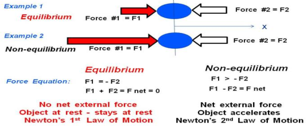
In Example 1 on the slide, we show a blue ball that is being pushed by two forces, labelled Force #1 F1 and Force #2 F2. Remember that forces are vector quantities and direction is important. Two forces with the same magnitude but different directions are not equal forces. In fact,
F1 = - F2
For the coordinate system shown with the letter X below the ball. If we sum up the forces acting on the ball, we obtain the force equation on the left:
F1 + F2 = F net = 0
Where F net is the net force acting on the ball. Because the net force is equal to zero, the forces in Example 1 are acting in equilibrium.
There is no net force acting on the ball in Example 1. Since the ball is initially at rest (velocity equals zero), the ball will remain at rest according to Newton's first law of motion. If the ball was travelling with a uniform velocity, it would continue travelling at the same velocity.
In Example 2, we have increased the magnitude of Force #1 so that it is much greater than Force #2. The forces are no longer in equilibrium. The force equation remains the same, but the net force is not equal to zero. The magnitude of the net force is given by:
F1 > - F2
F1 + F2 = F net
|F net| = |F1| - |F2|
Where the "| |" symbols indicate the magnitude of the quantity included between the ends. The direction of the net force would be in the positive X direction because F1 is greater then F2. According to Newton's second law of motion, the ball would begin to accelerate to the right. Because there is a net force in Example 2, the forces are not in equilibrium.
Friction:
Coulomb (1736-1806) determined that the frictional force Friction between two bodies which are pressed together with a normal force FN exhibit the following simple properties in a rough approximation:
A. Static Friction. In order to set in motion a body lying on an even surface in a
State of rest, a critical force, the force of static friction Fs, must be overcome. This
Force is roughly proportional to the normal force FN 1:
Fs = μs N F.
The coefficient μs is called the coefficient of static friction. It is dependent on the
Pairing of the contacting materials, however, shows almost no dependence on contact area or roughness.
B. Kinetic Friction FR is the resisting force which acts on a body after the Force of static friction has been overcome. Coulomb experimentally determined the following properties of kinetic friction:
Kinetic friction is proportional to the normal force FN:
FR = μk N F
It shows no considerable dependence on the contact area or roughness of the
Surface.
The coefficient of kinetic friction is approximately equal to the coefficient of
Static friction:
μk s ≈μ
This proportionality is known as Amontons’ law.
1) Frictional force always acts in opposite direction in which body tends to move
2) Frictional force is directly proportional to normal reaction
3) Frictional force is equal to net force acting in the direction in which object
Tends to move.
4) Frictional force does not depend on the surface area contacts.
5) Frictional force depends upon roughness of surface.
Friction is defined as a force of resistance acting on a body which prevents or retards slipping of the body relative to a second body. Experiments show that frictional forces act tangent (parallel) to the contacting surface in a direction opposing the relative motion or tendency for motion.
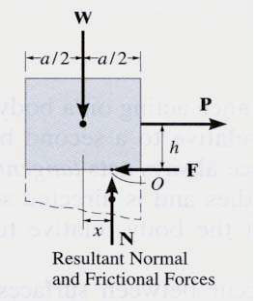
For the body shown in the figure to be in equilibrium, the following must be true:
F = P, N = W, and Wx = Ph
.
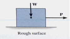
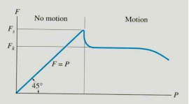
To study the characteristics of the friction force F, let us assume that tipping does not occur (i.e., “h” is small or “a” is large). Then we gradually increase the magnitude of the force P. Typically, experiments show that the friction force F varies with P, as shown in the right figure above.
The maximum friction force is attained just before the block begins to move (a situation that is called “impending motion”). The value of the force is found using Fs =s N, where s is called the coefficient of static friction. The value of s depends on the materials in contact. Once the block begins to move, the frictional force typically drops and is given by Fk = k N. The value of k (coefficient of kinetic friction) is less than s.
Steps for solving equilibrium problems involving dry friction:
1. Draw the necessary free body diagrams. Make sure that you show the friction force in the correct direction (it always opposes the motion or impending motion).
2. Determine the number of unknowns. Do not assume F =sN unless the impending motion condition is given.
3. Apply the equations of equilibrium and appropriate frictional equations to solve for the unknowns.
In any system where a belt or a cable is wrapped around a pulley or some other cylindrical surface, we have the potential for friction between the belt or cable and the surface it is in contact with. In some cases, such as a rope over a tree branch being used to lift an object, the friction forces represent a loss. In other cases such as a belt driven system, these friction forces are put to use transferring power from one pulley to another pulley.
 |  |
For analysis, we will start a flat, massless belt passing over a cylindrical surface. If we have an equal tension in each belt, the belt will experience a non-uniform normal force from the cylinder that is supporting it.
In a frictionless scenario, if we were to increase the tension on one side of the rope it would begin to slide across the cylinder. If friction exists between the rope and the surface though, the friction force will oppose with sliding motion, and prevent it up to a point.
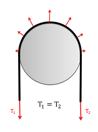 With equal tensions on each side of the belt, only a non-uniform normal force exists between the belt and the surface. | 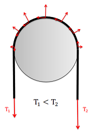 With unequal tensions, a friction force will also be present opposing the relative sliding of the belt to the surface. |
Friction in Flat Belts
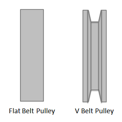
For a flat belt, the belt or cable will interact with the bottom surface. For a V belt, the belt or cable will interact with the sides of a groove.
A flat belt is any system where the pulley or surface only interacts with the bottom surface of the belt or cable. If the belt or cable instead fits into a groove, then it is considered a V belt.
When analyzing systems with belts, we are usually interested in the range of values for the tension forces where the belt will not slip relative to the surface. Starting with the smaller tension force on one side (T1) we, can increase the second tension force (T2) to some maximum value before slipping. For a flat belt, the maximum value for T2 will depend on the value of T1, the static coefficient of friction between the belt and the surface, and the contact angle between the belt and the surface (Beta) given in radians, as described in the equation below.
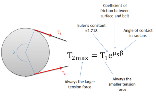
The maximum value of T2 before the belt starts slipping can be determined with the equation above.
Friction in V Belts
A V belt is any belt that fits into a groove on a pulley or surface. For the V belt to be effective, the belt or cable will need to be in contact with the sides of the groove, but not the base of the groove as shown in the diagram below. With the normal forces on each side, the vertical components must add up the the same as what the flat belt would have, but the added horizontal components of the normal forces, which cancel each other out, increase the potential for friction forces.
The equation for the maximum difference in tensions in V belt systems is similar to the equation in flat belt systems, except we use an "enhanced" coefficient of friction that takes into account the increased normal and friction forces possible because of the groove.
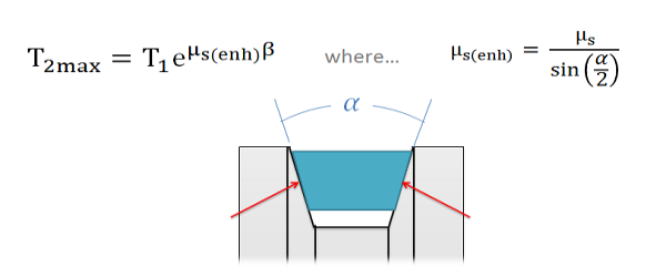 In a V belt, the "enhanced" coefficient of friction takes into account the coefficient of friction between the two materials as well as the groove angle.
As we can see from the equation above, steeper sides to the groove (which would result in a smaller angle alpha) result in an increased potential difference in the tension forces. The trade-off with steeper sides however is that the belt becomes wedged in the groove and will require force to unwedge itself from the groove as it leaves the pulley. This will cause losses that decrease the efficiency of the belt driven system. If very high tension differences are required, chain driven systems offer an alternative that is usually more efficient.
Torque and Power Transmission in Belt Driven Systems
In belt driven systems there is usually an input pulley and one or more output pulleys. To determine the maximum torque or power that can be transmitted by the belt, we will need to consider each of the pulleys independently, understanding that slipping occurring at either the input or the output will result in a failure of the power transmission.

A belt driven system with a single input and a single output.
The first step in determining the maximum torque or power that can be transmitted in the belt drive is to determine the maximum possible value for T2 before slipping occurs at either the input or output pulley (again slipping at either location cannot occur). To start we will often be given the "resting tension". This is the tension in the belt when everything is stationary and before power is transferred. Sometimes machines will have adjustments to increase or decrease the resting tension by slighting increasing or decreasing the distance between the pulleys. If we turn on the machine and increase the load torque at the output, the tension on the one side of the pulleys will remain constant as the resting tension while the tension on the other side will increase. Since the resting tension is constant and always the lower of the two tensions, it will be the T1 tension the equations discussed in earlier sections.
Though it is often wise to check, assuming the pulleys are the same material (and therefore the same coefficients of friction), it is often assumed that the belt will first slip at the smaller of the two pulleys in a single input, single output belt system. This is because the smaller pulley will have a the smaller contact angle (Beta), while all other values remain the same.
Once we have the maximum value for T2, we can use that to find the torque at the input pulley and the torque at the output pulley. Note that these two values will not be the same unless the pulleys are the same size. To find the torque, we will simply need to find the net moment exerted by the two tension forces, where the radius of the pulley is the moment arm.
Maximum input torque before slipping
Mmax=(T2max−T1)(rinput)
Maximum output torque before slipping
Mmax=(T2max−T1)(routput)
To find the maximum power we can transfer with the belt drive system, we will use the rotational definition of power, where the power is equal to the torque times the angular velocity in radians per second. Unlike the torque, the power at the input and the output will be the same assuming no inefficiencies.
Pmax=(Minputmax)(ωinput)=(Moutputmax)(ωoutput)