Unit-4
Simple Stress and Strain
Normal Stress
A normal stress is a stress that occurs when a member is loaded by an axial force. The value of the normal force for any prismatic section is simply the force divided by the cross sectional area.
Shear Stress
Normal stress is a result of load applied perpendicular to a member. Shear stress however results when a load is applied parallel to an area. Looking again at figure one, it can be seen that both bending and shear stresses will develop. Like in bending stress, shear stress will vary across the cross sectional area.
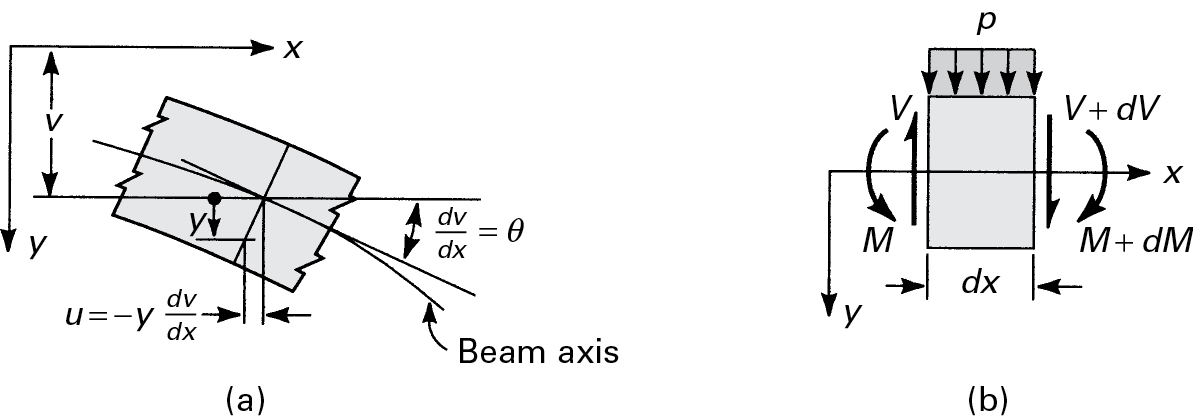
Fig 1
When a beam is bent by transverse loads, usually both a bending moment M and a shear force V act on each cross section. The distribution of the normal stress associated with the bending moment is given by the flexure formula, Eq. (5.4):

Where M and I are taken with respect to the z axis (fig 1).
In accordance with the assumptions of elementary bending equations 
And Equation 
We omit the contribution of the shear strains to beam deformation in these calculations. However, shear stresses do exist, and the shearing forces are the resultant of the stresses. The shearing stress τxy acting at section mn, which is assumed to be uniformly distributed over the area b·dx, can be determined on the basis of equilibrium of forces acting on the shaded part of the beam element (Fig. 5.9). Here b is the width of the beam a distance y1 from the neutral axis, and dx is the length of the element. The distribution of normal stresses produced by M and M + dM is indicated in the figure. The normal force distributed over the left face mr on the shaded area A* is equal to

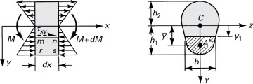
Fig 2 (a) Beam segment for analysing shear stress (b) cross section of beam.
Similarly, an expression for the normal force on the right face ns may be written in terms of M + dM. The equilibrium of x-directed forces acting on the beam element is governed by

From which we have

After substituting in Equation  we obtain the shear formula (also called the shear stress formula) for beams:

The integral represented by Q is the first moment of the shaded area A* with respect to the neutral axis z:

By definition,  is the distance from the neutral axis to the centroid of A*. In the case of sections of regular geometry,
  provides a convenient means of calculating Q. The shear force acting across the width of the beam per unit length

Is called the shear flow.
Stress-Strain diagram for Ductile material
Considering low Carbon Steel having Carbon content less 0.15% and its example is Mild Steel.
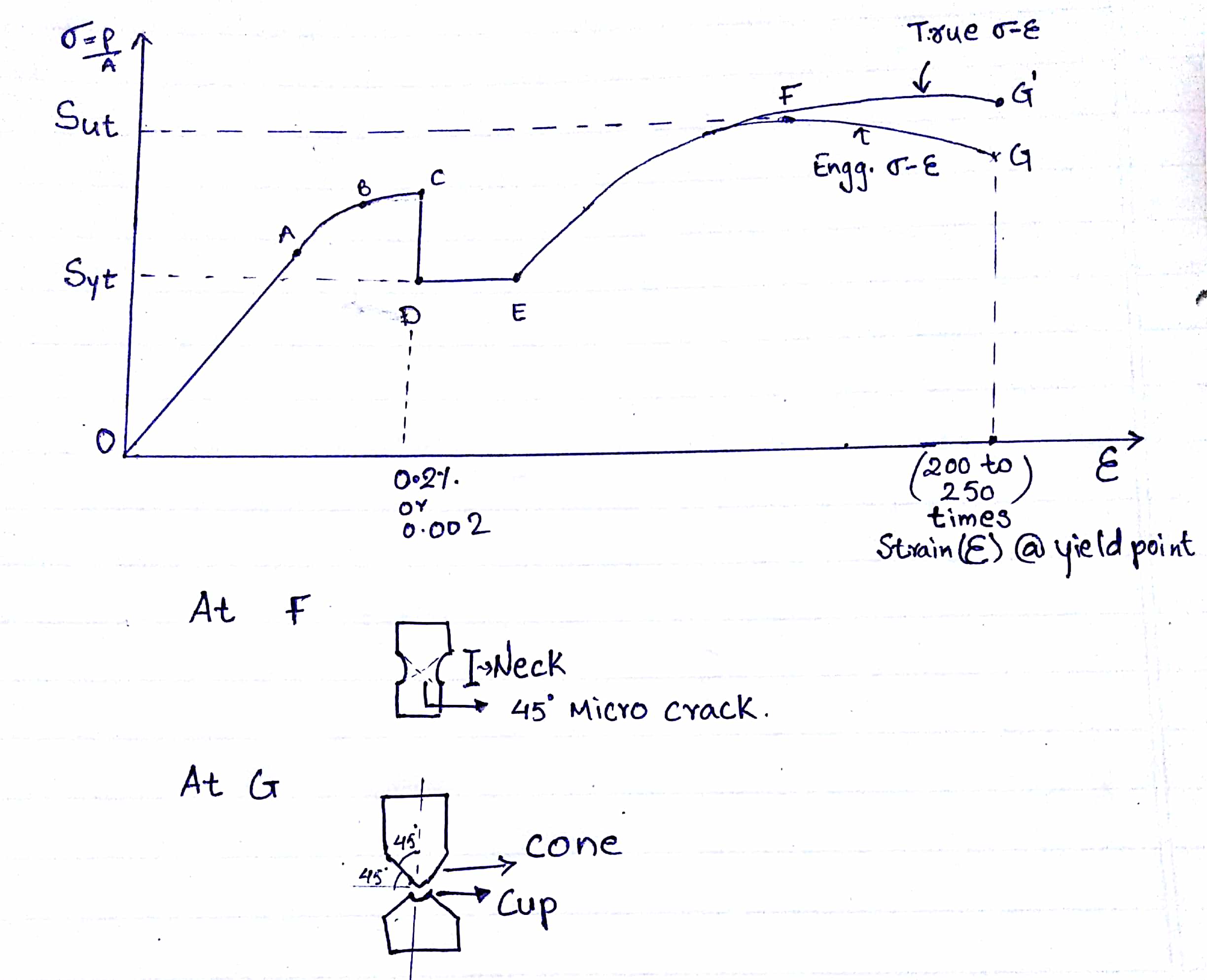
- Point A is the proportionality limit, up to A, stress is directly proportional to strain i.e Hook's law followed.
- Point B is the elastic limit.
- Point C is the upper yield point. At upper yield point, the resistance suddenly decreases. Therefore, stress is also decreased, this is the particular property of mild steel.
- Point D is the lower yield point which is the stable point for the design, the yield strength is considered to lower yield point
- Point F is the ultimate point. At point F necking starts and due to necking 45-degree micro cracks generates.
- Point G is the breaking point. At G component break into two pieces and failure is the cup-cone failure.The cup-cone failure is a shear failure.
Stress-Strain diagram for Brittle material
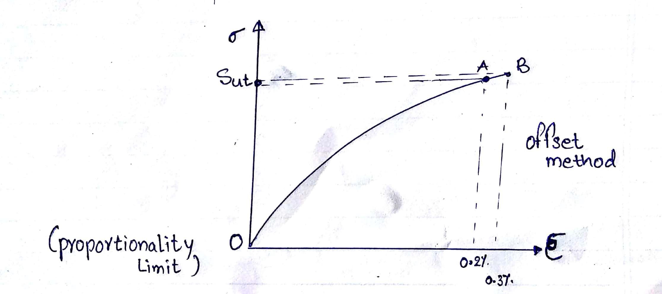
OA is non-linear elastic AB is the Strain Hardening.
- Brittle material never yields, a point similar to yield point is first cracking point, where simple cracks develop; which may expand further leading to failure.
- A point is the first cracking point. After first cracks develop, the material undergoes an increase in strain by widening the crack and fails almost at the same stress. Therefore for all calculation in brittle material design stress is ultimate or breaking stress i.e Sut.
Different types of stresses and their corresponding strains within elastic limit are related which are referred to as elastic constants. The three types of elastic constants are:
- Modulus of elasticity or Young’s modulus (E),
- Bulk modulus (K) and
- Modulus of rigidity or shear modulus (M, C or G).
There are three elastic constants;
- Normal stress/ Normal strain = Young’s modulus or Modulus of elasticity (E)
- Shear stress/ Shear strain = Shear modulus or Modulus of Rigidity (G)
- Direct stress/ Volumetric strain = Bulk modulus (K)
Young’s Modulus or Modulus of elasticity (E):
It is defined as the ratio of normal stress (σ) to the longitudinal strain (e).
E = (σn) / (e)
Modulus of Rigidity or Shear Modulus (G or C):
It is the ratio between shear stress (τ) and shear strain (es). It is denoted by G or C.
G= τ/es
Bulk Modulus or Volume Modulus of Elasticity (K):
It may be defined as the ratio of normal stress (on each face of a solid cube) to volumetric strain.
It is denoted by K. Bulk modulus is a measure of the resistance of a material to change of volume without change of shape or form.
K = Direct Stress / Volumetric strain
= σ/ev
Strain energy is defined as the energy stored in a body due to deformation. The strain energy per unit volume is known as strain energy density and the area under the stress-strain curve towards the point of deformation. When the applied force is released, the whole system returns to its original shape. It is usually denoted by U.
The strain energy formula is given as,
U = Fδ / 2
Where,
δ = compression,
F = force applied.
When stress σ is proportional to strain ϵ, the strain energy formula is given by,

Where,
σ = stress
 = strain
V = volume of body
Regarding Young’s modulus E, the strain energy formula is given as,
U = σ2 / 2E × V.
Where,
σ = stress,
E = Young’s modulus,
V = volume of body.
Compound stress and strains
The state of plane stress is defined as follows:
Plane Stress:
If the stress state at a material particle is such that the only non-zero stress components act in one plane only, the particle is said to be in plane stress.The axes are usually chosen such that the x y plane is the plane in which the stresses act, Fig. 3.5.1.
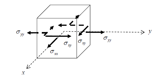
Figure 3.5.1: non-zero stress components acting in the x – y plane
The stress can be expressed in the matrix form
Example
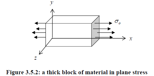
The thick block of uniform material shown in Fig. 3.5.2, loaded by a constant stress  in the x direction, will have
  and all other components zero everywhere. It is therefore in a state of plane stress.
Analysis of Plane Stress
Next are discussed the stress invariants, principal stresses and maximum shear stresses for the two-dimensional plane state of stress, and tools for evaluating them. These quantitiesare useful because they tell us the complete state of stress at a point in simple terms. Further,these quantities are directly related to the strength and response of materials. For example,the way in which a material plastically (permanently) deforms is often related to themaximum shear stress, the directions in which flaws/cracks grow in materials are oftenrelated to the principal stresses, and the energy stored in materials is often a function of thestress invariants.
Stress Invariants
A stress invariant is some function of the stress components which is independent of the coordinate system being used; in other words, they have the same value no matter where the x-y axes are drawn through a point. In a two dimensional space there are two stress invariants, labelled I1and I2. These are

These quantities can be proved to be invariant directly from the stress transformation equations, Eqns. 3.4.9 Physically, invariance of 1 I and 2 I means that they are the same for any chosen perpendicular planes through a material particle.Combinations of the stress invariants are also invariant, for example the important quantity

In 2-D, the transformation equations are

These are the expanded forms of σ′=Q⋅σ⋅QT′in 2-D. They can also be derived from a force balance of the figure shown here. It is interesting that stress is characterized as a tensor because it follows the transformation equation. But this is primarily a mathematical argument, and it would carry little weight if it were not connected to the physics of the force balance. The fact that the coordinate transform equation properly reflects the force balance at different orientations is what makes it relevant.
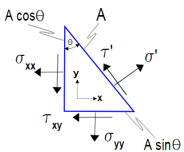
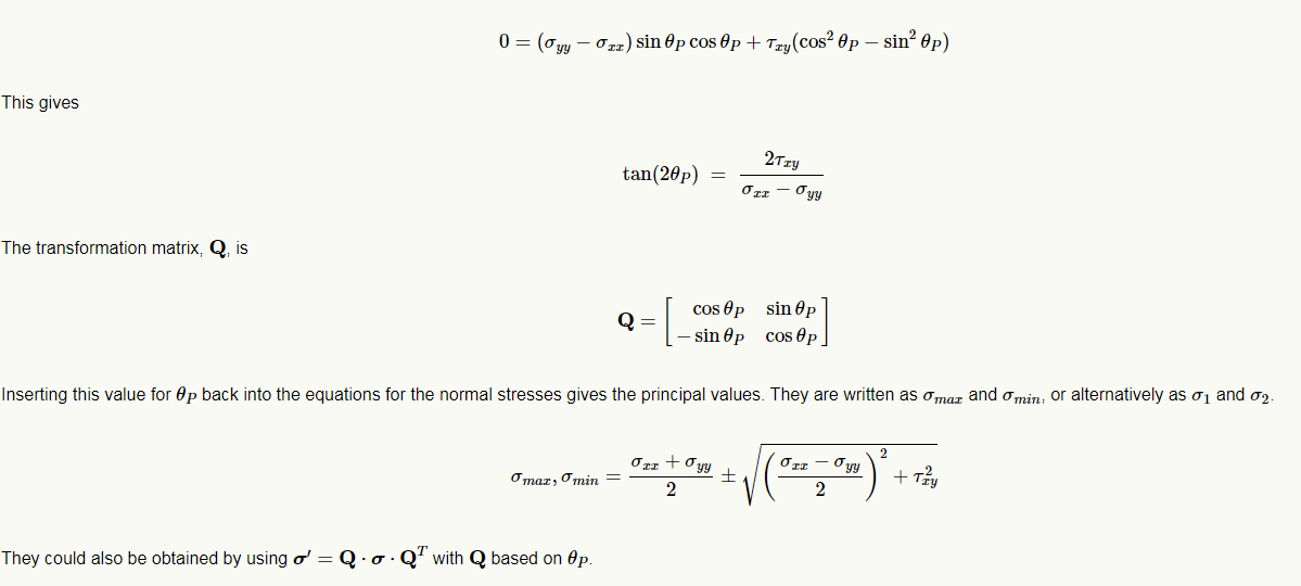
The principal stresses are the corresponding normal stresses at an angle, θPθP, at which the shear stress, τ′xyis zero.
The figure below shows the stresses corresponding to the pure shear case in the tensor transform webpage example. The blue square aligned with the axes clearly undergoes shear. But the red square inscribed in the larger blue square only sees simple tension and compression. These are the principal values of the pure shear case in the global coordinate system.
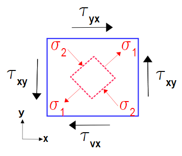
In 2-D, the principal stress orientation, θP, can be computed by setting τ′xy=0in the above shear equation and solving for θ to get θP, the principal stress angle.
Geologists and engineers calculate normal and shear stresses from the orientation and magnitude of two of the three principal stresses using the Mohr diagram. This diagram graphically illustrates in two dimensions the complex mathematical relationships between the components that make up a traction. Software for graphing the Mohr diagram is provided in Visualizing Stress. However, before using the software to analyze various states of stress, the components that make up the Mohr circle must be first explored
The fundamental stress equations derived in the previous section (Equations and ) can be rearranged as follows. For normal stress (sn)

And for shear stress (t)

Squaring both sides of Equations and reveals
 ……….1
……….1
And
 ………………………….2
Combining Equations (1) and (2) yields

Simplifying

Now recall the trigonometric relationship  . Substituting this relationship into the right hand side of equation results in

Recall from your college algebra class that the equation of a circle drawn in an x-y coordinate system is

Where r is the radius of the circle and (h, k) are the coordinates of the center of the circle. Comparing Equations and reveal that the fundamental stress equations define a circle in sn-t space centered on the point

With a radius of
Figure 1 illustrates a circle constructed from Equation . The circle represents the locus of all possible normal and shear stresses for a given state of stress acting on planes whose normals make an angle of q degrees to s1.
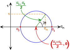
Figure 1 The Mohr circle constructed from Equation with a radius defined by Equation and a center with the coordinates in Equation.
Note further that the average stress is simply

Or, in three dimensions

In a Mohr diagram, average stress is the center of the Mohr circle. Differential stress is the difference between the maximum and minimum principal stresses. In a two dimensional Mohr diagram differential stress is the diameter of the Mohr circle.
Theories of failure are those theories which help us to determine the safe dimensions of a machine component when it is subjected to combined stresses due to various loads acting on it during its functionality.
Some examples of such components are as follows:
1. I.C. Engine crankshaft
2. Shaft used in power transmission
3. Spindle of a screw jaw
4. Bolted and welded joints used under eccentric loading
5. Ceiling fan rod
Theories of failure are employed in the design of a machine component due to the unavailability of failure stresses under combined loading conditions. Theories of failure play a key role in establishing the relationship between stresses induced under combined loading conditions and properties obtained from tension test like ultimate tensile strength (Sut) and yield strength (Syt).
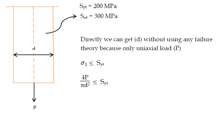
Member is subjected to both Twisting moment and uniaxial load, hence combined loading conditions. We cannot determine (d) directly in this case because failure stresses under combined loading conditions are unknown.
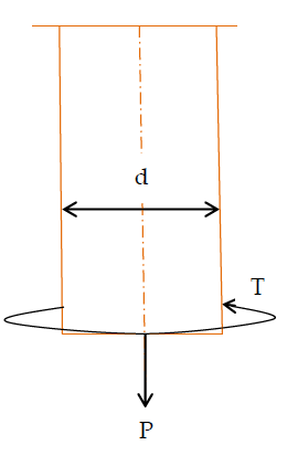
Member is subjected to both Twisting moment and uniaxial load, hence combined loading conditions. We cannot determine (d) directly in this case because failure stresses under combined loading conditions are unknown.
So, different scientists give relationships between Stresses induced under combined loading conditions and (Syt and Sut) obtained using tension test which are called theories of failure.
Various Theories of Failure
1. Maximum Principal Stress theory also known as RANKINE’S THEORY
2. Maximum Shear Stress theory or GUEST AND TRESCA’S THEORY
3. Maximum Principal Strain theory also known as St. VENANT’S THEORY
4. Total Strain Energy theory or HAIGH’S THEORY
5. Maximum Distortion Energy theory or VONMISES AND HENCKY’S THEORY