UNIT-3
ELECTROMAGNETIC THEORY
AMPERE’S LAW
Ampere’s circuital law (ACL) relates current to the magnetic field associated with the current.The magnetic field in space around an electric current is proportional to the electric current which serves as its source, just as the electric field in space is proportional to the charge which serves as its source.
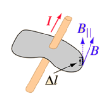
Figure 1
Ampere's Law states that
The integral around a closed path of the component of the magnetic field tangent to the direction of the path equals μ0 times the current intercepted by the area within the path.
 = μ0I ………..(1)
Ampere's Law tells that for any closed loop path, the sum of the length elements times the magnetic field in the direction of the length element is equal to the permeability times the electric current enclosed in the loop.
The equation (1) can be written as
 = I ………..(2)
Thus the line integral (circulation) of the magnetic field around some arbitrary closed curve is proportional to the total current enclosed by that curve.
In order to apply Ampère’s Law
All currents have to be steady (i.e.do not change with time)
Only currents crossing the area inside the path are taken in to account and have some contribution to the magnetic field
Current shave to be taken with their algebraic signs(those going “out” of the surface are positive, those going “in” are negative)-use right hand’s rule to determine directions and signs.
The total magnetic circulation is zero only in the following cases:-
- The enclosed net current is zero
- The magnetic field is normal to the selected path at any point
- The magnetic field is zero
Ampère’s Law can be useful when calculating magnetic fields of current distributions with a high degree of symmetry.
Finally, be aware that the form of Ampère’s Law addressed here applies to magnetostatics only. In the presence of a time-varying electric field, the right side of ACL includes an additional term known as the displacement current.
Ampere's Circuital Law
Consider a long thin wire carrying a steady current I. Suppose that the wire is orientated such that the current flows along the z-axis. Consider some closed loop C in the x-y plane which circles the wire in an anti-clockwise direction, looking down the z-axis. Suppose that dr is a short straight-line element of this loop. Let us form the dot product of this element with the local magnetic field  . Thus,
 ……....(3)
Where θ is the angle subtended between the direction of the line element and the direction of the local magnetic field. We can calculate a dw for every line element which makes up the loop C. If we sum all of the dw values thus obtained, and take the limit as the number of elements goes to infinity, we obtain the line integral
 …….....(4)
What is the value of this integral? In general, this is a difficult question to answer. However, let us consider a special case. Suppose that  is a circle of radius
  centred on the wire. In this case, the magnetic field-strength is the same at all points on the loop. In fact,
 ……......(5)
Moreover, the field is everywhere parallel to the line elements which make up the loop. Thus,
 …….......(6)
Or
 ……….....(7)
In other words, the line integral of the magnetic field around some circular loop C, centred on a current carrying wire, and in the plane perpendicular to the wire, is equal to μ0 times the current flowing in the wire. Note that this answer is independent of the radius r of the loop: i.e., the same result is obtained by taking the line integral around any circular loop centred on the wire.
In 1826, Ampère demonstrated that Eq. (7) holds for any closed loop which circles around any distribution of currents.
Determining Magnetic Field by Ampere’s Law
Suppose you have a long enough wire that carries a constant current I in amps. How would you determine the magnetic field wrapping the wire at any distance r from the wire?
In the figure below ( Figure 2), a long wire exists that carries current in Amps. We need to find out how much is the magnetic field at a distance r. Therefore, we sketch an imaginary route around the wire indicated by dotted blue toward the right in the figure.
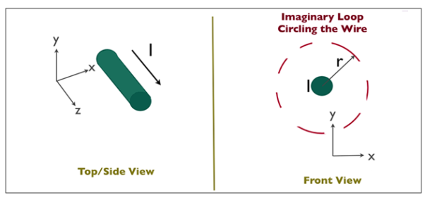
Figure 2
According to the second equation, if the magnetic field is integrated along the blue path, then it has to be equal to the current enclosed, I.
The magnetic field doesn’t vary at a distance r due to symmetry. The path length (in blue) in figure 2 equals to the circumference of a circle, 2πr.
When a constant value H is added to the magnetic field, the equation’s left side looks like this:
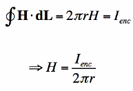
We have figured the magnitude of the field H. Since r is arbitrary, the value of the field H is known.
According to the equation, the magnetic field lowers in magnitude as we move wider. Hence, Ampere’s law can be applied to calculate the extent of the magnetic field surrounding the wire. The field H is a Vector field which reveals that each region has both a direction and a magnitude. The field’s direction is tangential at every point to the imaginary loops as shown in figure 3 and the right-hand rule finds the direction of the magnetic field.
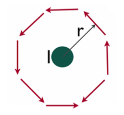
Figure 3
FARADAY’S LAW
Faraday’s law of electromagnetic induction (referred to as Faraday’s law) is a basic law of electromagnetism predicting how a magnetic field will interact with an electric circuit to produce an electromotive force (EMF). This phenomenon is known as electromagnetic induction.
Faraday’s law states that a current will be induced in a conductor which is exposed to a changing magnetic field. Lenz’s law of electromagnetic induction states that the direction of this induced current will be such that the magnetic field created by the induced current opposes the initial changing magnetic field which produced it. The direction of this current flow can be determined using Fleming’s right-hand rule.
Let us understand Faraday’s law by faraday‘s experiment.
FARADAY’S EXPERIMENT
In this experiment, Faraday takes a magnet and a coil and connects a galvanometer across the coil. At starting, the magnet is at rest, so there is no deflection in the galvanometer i.e. the needle of the galvanometer is at the center or zero position. When the magnet is moved towards the coil, the needle of the galvanometer deflects in one direction.
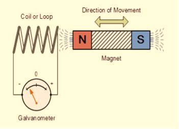
Figure 4
When the magnet is held stationary at that position, the needle of galvanometer returns to zero position. Now when the magnet moves away from the coil, there is some deflection in the needle but opposite direction, and again when the magnet becomes stationary, at that point respect to the coil, the needle of the galvanometer returns to the zero position.
Similarly, if the magnet is held stationary and the coil moves away, and towards the magnet, the galvanometer similarly shows deflection. It is also seen that the faster the change in the magnetic field, the greater will be the induced EMF or voltage in the coil.
Let us take a look at the following table. This table is showing the observation of faraday’s experiment.
Position of magnet | Deflection in galvanometer |
Magnet at rest | No deflection in the galvanometer |
Magnet moves towards the coil | Deflection in galvanometer in one direction |
Magnet is held stationary at same position (near the coil) | No deflection in the galvanometer |
Magnet moves away from the coil | Deflection in galvanometer but in the opposite direction |
Magnet is held stationary at the same position (away from the coil) | No deflection in the galvanometer |
CONCLUSION
From this experiment, Faraday concluded that whenever there is relative motion between a conductor and a magnetic field, the flux linkage with a coil changes and this change in flux induces a voltage across a coil.
Michael Faraday formulated two laws on the basis of the above experiments. These laws are called Faraday’s laws of electromagnetic induction.
FARADAY’S FIRST LAW
Any change in the magnetic field of a coil of wire will cause an emf to be induced in the coil. This emf induced is called induced emf and if the conductor circuit is closed, the current will also circulate through the circuit and this current is called induced current.
Method to change the magnetic field:
- By moving a magnet towards or away from the coil
- By moving the coil into or out of the magnetic field
- By changing the area of a coil placed in the magnetic field
- By rotating the coil relative to the magnet
FARADAY’S SECOND LAW
It states that the magnitude of emf induced in the coil is equal to the rate of change of flux that linkages with the coil. The flux linkage of the coil is the product of the number of turns in the coil and flux associated with the coil.
FARADAY LAW FORMULA
Consider, a magnet is approaching towards a coil. Here we consider two instants at time T1 and time T2. Coil has N number of turns.
Flux linkage with the coil at time,
 ………..(1)
Flux linkage with the coil at time,
 ………..(2)
Change in flux linkage,
 ………..(3)
Let this change in flux linkage be,
 ………..(4)
So, the Change in flux linkage
 ………..(5)
Now the rate of change of flux linkage
 ………..(6)
Take derivative on right-hand side we will get as N is number of turns of coils which is constant so taken out of derivative, we get
 ………..(7)
The rate of change of flux linkage
 ………..(8)
Where E is induced emf.
But according to Faraday’s law of electromagnetic induction, the rate of change of flux linkage is equal to induced emf.
 ………..(9)
Considering Lenz’s Law
Where:
- Flux Φ in Wb = B.A
- B = magnetic field strength
- A = area of the coil
FACTORS ON WHICH INDUCED EMF DEPEND
- By increasing the number of turns in the coil i.e. N, from the formulae derived above it is easily seen that if the number of turns in a coil is increased, the induced emf also gets increased.
- By increasing magnetic field strength i.e. B surrounding the coil- Mathematically, if magnetic field increases, flux increases and if flux increases emf induced will also get increased. Theoretically, if the coil is passed through a stronger magnetic field, there will be more lines of force for the coil to cut and hence there will be more emf induced.
- By increasing the speed of the relative motion between the coil and the magnet – If the relative speed between the coil and magnet is increased from its previous value, the coil will cut the lines of flux at a faster rate, so more induced emf would be produced.
APPLICATIONS OF FARADAY’S LAW
Faraday law is one of the most basic and important laws of electromagnetism. This law finds its application in most of the electrical machines, industries, and the medical field, etc.
- Power transformers function based on Faraday’s law
- The basic working principle of the electrical generator is Faraday’s law of mutual induction.
- The Induction cooker is the fastest way of cooking. It also works on the principle of mutual induction. When current flows through the coil of copper wire placed below a cooking container, it produces a changing magnetic field. This alternating or changing magnetic field induces an emf and hence the current in the conductive container, and we know that the flow of current always produces heat in it.
- Electromagnetic Flow Meter is used to measure the velocity of certain fluids. When a magnetic field is applied to an electrically insulated pipe in which conducting fluids are flowing, then according to Faraday’s law, an electromotive force is induced in it. This induced emf is proportional to the velocity of fluid flowing.
- From bases of Electromagnetic theory, Faraday’s idea lines of force is used in well-known Maxwell’s equations. According to Faraday’s law, change in magnetic field gives rise to change in electric field and the converse of this is used in Maxwell’s equations.
- It is also used in musical instruments like an electric guitar, electric violin, etc.
DIFFERENTIAL FORM OF FARADAY’S LAW
Time-varying magnetic field will always produce an electric field. According to the faraday’s law “Whenever there are n-turns of conducting coil in a closed path which is placed in a time-varying magnetic field, an alternating electromotive force gets induced in each and every coil.” This is given by Lenz’s law. Which states that An induced electromotive force always opposes the time-varying magnetic flux.
When two coils with N number of turns; A primary coil and Secondary coil. The primary coil is connected to an alternating current source and the secondary coil is connected in a closed loop and is placed at a small distance from the primary coil. When an AC current passes through the primary coil, an alternating electromotive force gets induced in the secondary coil.
Mathematically it is expressed as –
Alternating emf, emfalt=−Ndϕ/dt ——–(1)
Where,
N is the number of turns in a coil
𝜙 is the scalar magnetic flux.
The negative sign indicates that the induced emf always opposes the time-varying magnetic flux.
Let N=1,
⇒emfalt= − ——-(2)
Here, the scalar magnetic flux can be replaced by –
ϕ=∬B⃗ .ds⃗ ——–(3)
Substitute equation (3) in (2)
Emfalt= − ∬B⃗ .ds⃗
Which is an partial differential equation given by-
Emfalt= ∬− ds⃗ ———–(4)
The alternating electromotive force induced in a coil is basically a closed path
⇒emfalt = ∮E⃗ .dl⃗ ——-(5)
Substituting equation (5) in (4) we get-
⇒∮E⃗ dl⃗ = ∬− ds⃗ —–(6)
The closed line integral can be converted into surface integral using Stoke’s theorem. Which states that “Closed line integral of any vector field is always equal to the surface integral of the curl of the same vector field”
⇒∮E⃗ dl⃗ =∬( ×E⃗ ).ds⃗ ———(7)
Substituting equation (7) in (6) we get-
⇒=∬( ×E⃗ ).ds⃗ = ∬−
 ds⃗ ———(8)
The surface integral can be cancelled on both sides. Thus, we arrive at
 × E⃗ =
Hence, we can conclude that the time-varying magnetic field will always produce an electric field.
This is the differential form of faraday’s law. It is also known as Maxwell-Faraday Equation.
For the static magnetic field, which states that Static electric field vector is an irrotational vector.
Static field implies the time-varying magnetic field is zero,
⇒ =0 ⇒
=0 ⇒ × E⃗ =0
Hence it is an irrotational vector.
Maxwell equations are of fundamental importance since they describe the whole of classical electromagnetic phenomena.
Maxwell's Equations are a set of 4 complicated equations that describe the world of electromagnetics. These equations describe how electric and magnetic fields propagate, interact, and how they are influenced by objects.
Maxwell was one of the first to determine the speed of propagation of electromagnetic (EM) waves was the same as the speed of light - and hence to conclude that EM waves and visible light were really the same thing.
These equations are rules the universe uses to govern the behaviour of electric and magnetic fields. A flow of electric current will produce a magnetic field. If the current flow varies with time (as in any wave or periodic signal), the magnetic field will also give rise to an electric field. Maxwell's Equations shows that separated charge (positive and negative) gives rise to an electric field - and if this is varying in time as well will give rise to a propagating electric field, further giving rise to a propagating magnetic field.
From a classical perspective, light can be described as waves of electromagnetic radiation. As such, Maxwell equations are very useful to illustrate a number of the characteristics of light including polarization.
We are just to stating these equations without derivation. Since our goal is simply to apply them, the usual approach will be followed.
Maxwell’s first equation (Gauss' Law for Electric Fields)
Gauss' Law is the first of Maxwell's Equations which dictates how the Electric Field behaves around electric charges. Gauss' Law can be written in terms of the Electric Flux Density and the Electric Charge Density as:
∇·E = ρ/ε0
0r
∇·D = ρ
Hence, Gauss' law is a mathematical statement that the total Electric Flux exiting any volume is equal to the total charge inside. Hence, if the volume in question has no charge within it, the net flow of Electric Flux out of that region is zero. If there is positive charge within a volume, then there exists a positive amount of Electric Flux exiting any volume that surrounds the charge. If there is negative charge within a volume, then there exists a negative amount of Electric Flux exiting (i.e. the Electric Flux enters the volume).
Maxwell’s Second equation (Gauss' Magnetism law)
We know that Gauss' Law for Electric Fields states that the divergence of the Electric Flux Density D is equal to the volume electric charge density. But the second equation, Gauss' Magnetism law states that the divergence of the Magnetic Flux Density (B) is zero.
Why? Why isn't the divergence of B equal to the magnetic charge density?
Well - it is. But it just so happens that no one has ever found magnetic charge - not in a laboratory or on the street or on the subway. And therefore, until this hypothetical magnetic charge is found, we set the right side of Gauss' Law for Magnetic Fields to zero:
∇·B = 0
Now, you may have played with magnets when you were little, and these magnetic objects attracted other magnets similar to how electric charges repel or attract like electric charges. However, there is something special about these magnets - they always have a positive and negative end. This means every magnetic object is a magnetic dipole, with a north and South Pole. No matter how many times you break the magnetic in half, it will just form more magnetic dipoles. Gauss' Law for Magnetism states that magnetic monopoles do not exist - or at least we haven't found them yet.
Maxwell’s Third equation (Faraday's Law)
Faraday figured out that a changing Magnetic Flux within a circuit (or closed loop of wire) produced an induced EMF, or voltage within the circuit. Maxwell gives his second equation from this.
Faraday's Law tells us that a magnetic field that is changing in time will give rise to a circulating E-field. This means we have two ways of generating E-fields - from Electric Charges (or flowing electric charge, current) or from a magnetic field that is changing.
∇×E = −∂B/∂t
Maxwell’s Fourth equation(Ampere's Law)
Ampere's Law tells us that a flowing electric current gives rise to a magnetic field that circles the wire. In addition to this, it also says that an Electric Field that is changing in time gives rise to a magnetic field that encircles the E-field - this is the Displacement Current term that Maxwell himself introduced.
This means there are 2 ways to generate a solenoidal (circulating) H-field - a flowing electric current or a changing Electric Field. Both give rise to the same phenomenon.
The modified form of Ampere's Law s given by Maxwell’s third equation
∇×H = J + ∂D/∂t
Maxwell’s four equations are given by
∇·E = ρ/ε0 (1)
∇·B = 0 (2)
∇×E = −∂B/∂t (3)
∇×H = J + ∂D/∂t (4)
These equations illustrate the unique coexistence in nature of the electric field and the magnetic field. The first two equations give the value of the given flux through a closed surface, and the second two equations give the value of a line integral around a loop. In this notation,
∇=(∂/∂x, ∂/∂y, ∂/∂z)
E is the electric vector
B is the magnetic induction
ρ is the electric charge density
j is the electric current density
ε0 is the permittivity of free space
c is the speed of light.
In addition to Maxwell equations, the following identities are useful:
J = σE (5)
D = εE (6)
B = μH (7)
Here,
D is the electric displacement
H is the magnetic vector
σ is the specific conductivity
ε is the dielectric constant (or permittivity)
μ is the magnetic permeability
Displacement current is the rate of change of electric displacement field.
The type of current which passes through a conductor is known as conduction current and is caused by the actual movement of electrons through the conductor. This type of current is mostly used in our day to day life. There is also another kind of current, which is known as displacement current. Displacement current differs from the conduction current because the displacement current does not involve electrons' movement. The displacement current has enormous importance for the propagation of electromagnetic waves. In electromagnetism, displacement current is a quantity appearing in Maxwell's equations that is defined in terms of the rate of change of electric displacement field.
Displacement current has the units of electric current density, and it has an associated magnetic field just as actual currents do.
It is mathematically represented as
ID = JD S = S 
Where
S = Area of the plate of the capacitor
ID =Displacement current
JD =Displacement current density
D = εE where ε is permittivity of the medium
During the charging and discharging process of the capacitor, the electric current flows through the wires of the circuit. However, no current flow between the plates of the capacitor.
According to Ampere's law, the magnetic field should not present between the plates as there is no current, but in reality, the magnetic field exists there. Maxwell formulated this limitation of Ampere's law by adding a term in the equation of Ampere's law to solve the issue.
Maxwell predicted that the magnetic field will still exist even in the absence of conduction current, and the magnetic field may be associated with the changing electric field. This theory of Maxwell was experimentally proved.
Since the magnetic field is associated with the electric field, the general displacement current formula is given by,
 = μ0( I+ε0
 )
)
This equation is the generalized formula of Maxwell-Ampere law.
Displacement Current Definition
The displacement current (ID) is the part which Maxwell has added to the Ampere's law.
ID = ε0
ε0= Permittivity of free space
 Derivative of electric flux
Electric flux is the time rate change of flow of the electric field through a surface. If we take the derivative of electric flux, we get the rate of change of the electric field of a given area concerning time.
Modification of Ampere’s circuital law. Maxwell modified Ampere’s law by giving the concept of displacement current D and so the concept of displacement current density Jd for time varying fields.
For time varying fields should be written as
∇xH=J+jd (7)
By taking divergence of equation(7) , we get
∇ .(∇ xH)= ∇.J+ ∇.Jd
As divergence of the curl of a vector is always zero, therefore
∇ .(∇ x H)=0
It means, ∇ .(J+ .Jd)=0
Or ∇. J= –∇.Jd
But from equation of continuity for time varying fields,
∇.J= – dρ/ dt
By comparing above two equations of .j ,we get
∇ .jd =d(∇ .D)/dt (8)
Because from Maxwell’s first equation ∇ .D=ρ
As the divergence of two vectors is equal only if the vectors are equal.
Thus Jd= dD/dt
Substituting above equation in equation (7), we get
∇xH=J+dD/dt (9)
Here ,dD/dt= Jd=Displacement current density
J=conduction current density
D= displacement current
The equation(9) is the Differential form of Maxwell’s fourth equation or Modified Ampere’s circuital law.
Intergal form
Taking surface integral of equation (9) on both sides, we get
∫( ∇xH).dS=∫(J+ dD/dt).dS
Apply stoke’s theorem to L.H.S. Of above equation, we get
∫( ∇xH).dS=∫ H.dL
Comparing the above two equations ,we get
∫H.dL=∫(J+dD/dt).dS
Statement of modified Ampere’s circuital Law
The line integral of the Magnetic field H around any closed path or circuit is equal to the conductions current plus the time derivative of electric displacement through any surface bounded by the path.
Equation(9) is the integral form of Maxwell’s fourth equation.
The modified form of Ampere's Law s given by Maxwell’s fourth equation in differential form
∇×H = J + ∂D/∂t
Maxwell’s third equation in integral form
∫( ∇xH).dS=∫(J+ dD/dt).dS
Maxwell Equations
Maxwell equations are of fundamental importance since they describe the whole of classical electromagnetic phenomena.
Maxwell's Equations are a set of 4 complicated equations that describe the world of electromagnetics. These equations describe how electric and magnetic fields propagate, interact, and how they are influenced by objects.
Maxwell was one of the first to determine the speed of propagation of electromagnetic (EM) waves was the same as the speed of light - and hence to conclude that EM waves and visible light were really the same thing.
These equations are rules the universe uses to govern the behaviour of electric and magnetic fields. A flow of electric current will produce a magnetic field. If the current flow varies with time (as in any wave or periodic signal), the magnetic field will also give rise to an electric field. Maxwell's Equations shows that separated charge (positive and negative) gives rise to an electric field - and if this is varying in time as well will give rise to a propagating electric field, further giving rise to a propagating magnetic field.
From a classical perspective, light can be described as waves of electromagnetic radiation. As such, Maxwell equations are very useful to illustrate a number of the characteristics of light including polarization.
Maxwell’s first equation (Gauss' Law for Electric Fields)
Gauss' Law is the first of Maxwell's Equations which dictates how the Electric Field behaves around electric charges. Gauss' Law can be written in terms of the Electric Flux Density and the Electric Charge Density as:
∇·E = ρ/ε0
0r
∇·D = ρ
Hence, Gauss' law is a mathematical statement that the total Electric Flux exiting any volume is equal to the total charge inside. Hence, if the volume in question has no charge within it, the net flow of Electric Flux out of that region is zero. If there is positive charge within a volume, then there exists a positive amount of Electric Flux exiting any volume that surrounds the charge. If there is negative charge within a volume, then there exists a negative amount of Electric Flux exiting (i.e. the Electric Flux enters the volume).
The First Maxwell’s equation (Gauss’s law for electricity)
The Gauss’s law states that flux passing through any closed surface is equal to 1/ε0 times the total charge enclosed by that surface.
Integral form of Maxwell’s 1st equation
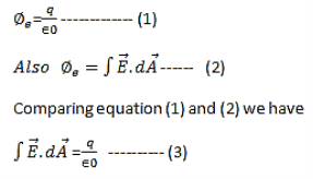
It is the integral form of Maxwell’s 1st equation.
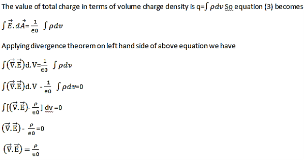
Maxwell’s first equation in differential form
It is called the differential form of Maxwell’s 1st equation.
The Second Maxwell’s equation (Gauss’s law for magnetism)
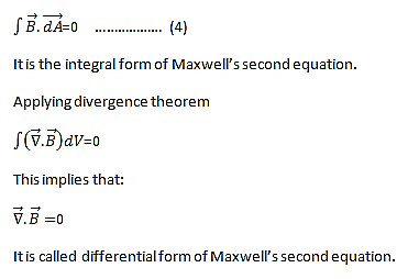
The Gauss’s law for magnetism states that net flux of the magnetic field through a closed surface is zero because monopoles of a magnet do not exist.
We know that Gauss' Law for Electric Fields states that the divergence of the Electric Flux Density D is equal to the volume electric charge density. But the second equation, Gauss' Magnetism law states that the divergence of the Magnetic Flux Density (B) is zero.
Why? Why isn't the divergence of B equal to the magnetic charge density?
Well - it is. But it just so happens that no one has ever found magnetic charge - not in a laboratory or on the street or on the subway. And therefore, until this hypothetical magnetic charge is found, we set the right side of Gauss' Law for Magnetic Fields to zero:
∇·B = 0
Now, you may have played with magnets when you were little, and these magnetic objects attracted other magnets similar to how electric charges repel or attract like electric charges. However, there is something special about these magnets - they always have a positive and negative end. This means every magnetic object is a magnetic dipole, with a north and South Pole. No matter how many times you break the magnetic in half, it will just form more magnetic dipoles. Gauss' Law for Magnetism states that magnetic monopoles do not exist - or at least we haven't found them yet.
Maxwell’s Third equation (Faraday's Law)
Faraday figured out that a changing Magnetic Flux within a circuit (or closed loop of wire) produced an induced EMF, or voltage within the circuit. Maxwell gives his second equation from this.
Faraday's Law tells us that a magnetic field that is changing in time will give rise to a circulating E-field. This means we have two ways of generating E-fields - from Electric Charges (or flowing electric charge, current) or from a magnetic field that is changing.
∇×E = −∂B/∂t
According to Faraday’s law of electromagnetic induction
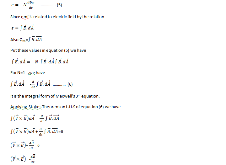
It is the differential form of Maxwell’s third equation.
Maxwell’s fourth equation (Ampere's Law)
Ampere's Law tells us that a flowing electric current gives rise to a magnetic field that circles the wire. In addition to this, it also says that an Electric Field that is changing in time gives rise to a magnetic field that encircles the E-field - this is the Displacement Current term that Maxwell himself introduced.
This means there are 2 ways to generate a solenoidal (circulating) H-field - a flowing electric current or a changing Electric Field. Both give rise to the same phenomenon.
The modified form of ampere Law is given by
H.dL=(J+dD/dt)
Take integration on both sides we have
∫H.dL=∫(J+dD/dt).dS
Apply stoke’s theorem to L.H.S. Of above equation, we get
∫( ∇xH).dS=∫ H.dL
Now the above equation is written as
∫( ∇xH).dS =∫(J+dD/dt).dS
By cancelling the surface integral on both sides we have
∇xH =J+dD/dt
Which is the differential form of Maxwell’s equation.
This can also be written in the form B
The Ampere-Maxwell Law

Begin with the Ampere-Maxwell law in integral form.

Invoke Stokes' theorem.

Set the equation to 0.

Physical Significance Of Each Equation
Physical significance of Maxwell’s Ist equation
∇·E = ρ/ε0
According to this total electric flux through any closed surface is 1/0 times the total charge enclosed by the closed surfaces, representing Gauss's law of electrostatics, As this does not depend on time, it is a steady state equation. Here for positive , divergence of electric field is positive and for negative divergence is negative. It indicates that is scalar quantity.
Physical significance of Maxwell’s 2nd equation
∇·B = 0
It represents Gauss law of magnetostatic as ∇·B = 0 resulting that isolated magnetic poles or magnetic monopoles cannot exist as they appear only in pairs and there is no source or sink for magnetic lines of forces. It is also independent of time i.e. steady state equation.
Physical significance of Maxwell’s 3rd equation
∇×E = −∂B/∂t
It shows that with time varying magnetic flux, electric field is produced in accordance with Faraday is law of electromagnetic induction. This is a time dependent equation.
Physical significance ofMaxwell’s 4th equation
∇×H = J + ∂D/∂t
This is a time dependent equation which represents the modified differential form of Ampere's circuital law according to which magnetic field is produced due to combined effect of conduction current density and displacement current density.
When electromagnetic wave travels in space, it carries energy and energy density is alwaysassociated with electric fields and magnetic fields.
The rate of energy travelled through per unit area i.e. the amount of energy flowing throughper unit area in the perpendicular direction to the incident energy per unit time is called Poyntingvector.
Mathematically Poynting vector is represented as
 =
=  =(
=( ) (i)
) (i)
The direction of Poynting vector is perpendicular to the plane containing  and
and . Poynting vector is also called as instantaneous energy flux density. Here rate of energy transfer
  is perpendicular to both
  and
and . It represents the rate of energy transfer per unit area.
UNIT
Its unit is W/m2.
Poynting Theorem
Poynting theorem states that the net power flowing out of a given volume V is equal to the time rate of decrease of stored electromagnetic energy in that volume decreased by the conduction losses.
i.e. total power leaving the volume =Rate of decrease of stored electromagnetic energy – ohmic power dissipated due to motion of charge
Proof
The energy density carried by the electromagnetic wave can be calculated using Maxwell's equations
Div = 0 ...(i)
Div =0 ...(ii)
Curl  = -
= -  …(iii)
Curl  =
=  +
+  …(iv)
…(iv)
Taking scalar product of (3) with H and (4) with 
i.e.  curl
curl  = -
= -  ……(v)
……(v)
And curl
curl  =
=  +
+  .
.  …..(vi)
Doing (vi) – (v) i.e.


So from equation (vii)

Or

Integrating equation (viii) over a volume V enclosed by a Surface S

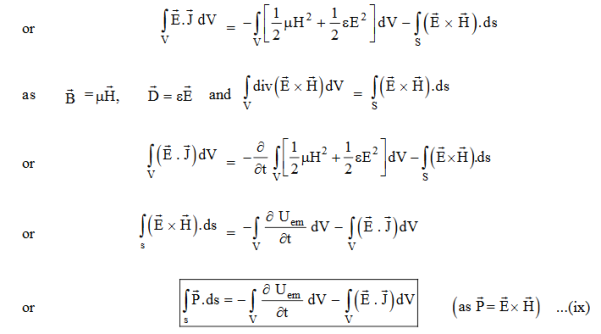
Total power leaving the volume = rate of decrease of stored e.m. Energy -ohmic power dissipated due to charge motion
This equation (ix) represents the Poynting theorem according to which the net power flowing out of a given volume is equal to the rate of decrease of stored electromagnetic energy in that volume minus the conduction losses.
In equation (ix)  .ds represents the amount of electromagnetic energy crossing the closed surface per second or the rate of flow of outward energy through the surface S enclosing volume V i.e. it is Poynting vector.
The term represent

The energy stored in electric and magnetic fields respectively and their sum denotes the total energy stored in electromagnetic field. So total terms gives the rate of decrease of energy stored in volume V due to electric and magnetic fields.

Gives the rate of energy transferred into the electromagnetic field.
This is also known as work-energy theorem. This is also called as the energy conservation law in electromagnetism.
Wave is nothing but a pattern of disturbance which propagates and carry energy with it. You can produce a wave on a rope by moving one end of the rope up and down. The wave produces on rope needs a medium to propagate and here medium is rope itself. This type of waves is known as mechanical waves. But in the case of Electromagnetic waves, they don't need a medium to propagate. Electromagnetic waves are waves that are created as a result of variations of electric field and a magnetic field. Or we can say that Electromagnetic waves are nothing but changing magnetic and electric fields. Electromagnetic waves are also known to be solutions of Maxwell's equations. And Maxwell's equations are the fundamental equations of electrodynamics. Electromagnetic waves can transmit energy and travel through a vacuum.
Light waves are examples of electromagnetic waves. Generally, Electromagnetic waves are shown by a sinusoidal graph.
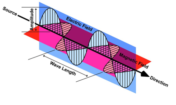
Figure 5
As shown in figure Electromagnetic waves consist of time-varying electric and magnetic fields and they are perpendicular to each other and these both fields are also perpendicular to the direction of propagation of waves.
Maxwell’s four equations are given by
∇·E = ρ/ε0 (1)
∇×E = −∂B/∂t (2)
∇×H = J + ∂D/∂t (3)
∇·B = 0 (4)
These equations illustrate the unique coexistence in nature of the electric field and the magnetic field. The first two equations give the value of the given flux through a closed surface, and the second two equations give the value of a line integral around a loop. In this notation,
∇=(∂/∂x, ∂/∂y, ∂/∂z)
E is the electric vector
B is the magnetic induction
ρ is the electric charge density
j is the electric current density
ε0 is the permittivity of free space
c is the speed of light.
In addition to Maxwell equations, the following identities are useful:
J = σE (5)
D = εE (6)
B = μH (7)
Here,
D is the electric displacement
H is the magnetic vector
σ is the specific conductivity
ε is the dielectric constant (or permittivity)
μ is the magnetic permeability
Free space or non-conducting medium. We know that non conducting medium means no current so conductivity is zero i.e. σ=0
So current density J=σE will also become zero as σ=0 Also free space means no charges which leads to ρ=0. These points mentioned below.
(a) No condition current i.eσ=0, thus J=0 ( J=σE)
(b) No charges (i.eρ=0)
For the case of no charges or currents, that is, j = 0 and ρ = 0, and a homogeneous medium. Using these the Maxwell equation can rewritten as
∇.D=0 or ∇.E=0 as ρ=0 (12)
∇ x E= -dB/dt or ∇ x E= -μdH/dt because B = μH (13)
∇x H=d D/dt or ∇ x H = εdE/dt (J=0) and D = εE (14)
∇.B=0 (15)
WAVE EQUATION IN TERMS OF ELECTRIC FIELD INTENSITY, E
Now taking curl of second Maxwell’s equation (13) ,we get
∇x(∇ x E)=- μd/dt (∇ x H)
Applying standard vector identity, that is [∇ *(∇*E)=∇(∇.E)-∇2E] on left hand side of above equation, we get
∇ (∇ .E)-∇2E= -μd/dt (∇x H) (16)
Substituting equations (13) and (14) in equations (16) ,we get
-∇2E= – μεd/dt (dE/dt)
Or ∇2E=με d 2 E/dT2 (17)
Equation (17) is the required wave equation in terms of electric field intensity, E for free space . This is the law that E must obey.
WAVE EQUATION IN TERMS OF MAGNETIC FIELD INTENSITY, H
Take curl of fourth Maxwell’s equation (14) ,we get
∇x(∇xH)=ε d/dt(∇xE)
Applying standard vector identity that is
[∇*(∇*H)=∇ (∇.H)-∇2H]
On left side of above equation , we get
∇(∇.H)-∇2H= ε d/dt(∇xE) (18)
Substituting equations (14) and (13) in equation(18) ,we get
-∇2H= – μεd/dt(dH/dt)
Or
∇2H=με d2H/dt2 (19)
Equations (19) is the required wave equation in terms of magnetic field intensity, H and this is the law that H must obey
For vacuum μ=μ0 and ε=ε0, equations (17) and (19) will become
∇2 E=μ0ε0 d2E/dt2 (20)
And ∇2H= μ0ε0 d2H/dt2 (21)
This leads to an expression for the velocity of propagation
From equation both equations (20) and (21) have the form of the general wave equation for a wave

(x,t) traveling in the x direction with speed v. Equating the speed with the coefficients, we derive the speed of electric and magnetic waves, which is a constant that we symbolize with “c”
It is useful to note that in vacuum
c2=1/ε0μ0
Where μ0 is the permeability of free space

Let us rewrite the equation (20) and (21) for one dimension.
Or d 2 E/dx2 =μ0ε0 d 2 E/dt2 (22)
d2H/dx2= μ0ε0 d2H/dt2 (23)
The simplest solutions to the differential equations (22) and (23) are sinusoidal wave functions:
E(x) = Emax cos(kx-t) (24)
B(x) = Bmaxcos(kx-t) (25)
Where k = 2π/λis the wavenumber , ω = 2πƒ is the angular frequency, λ is the wavelength, f is the frequency and ω /k=f=v= c.
Transverse Nature
In this section we will study the variation of field of  and
and  of an em plane wave with space and time.
Variation With Space
First we will consider the variation with space. Suppose a plane em wave is propagating along x axis. Then the values of the field vectors  and
and  will be constant on any plane parallel to YZ plane. That is:
For 
 =
= =
= =
= = 0 …………(1)
For 
 =
= =
= =
= = 0 …………(2)
From Maxwell’s equation for free space, we have
∇.E=0
Therefore
 +
+ +
+ =0
=0
Which gives
 =0 …………(3)
Also From Maxwell’s equation for free space, we have
∇.B=0 we have ∇.H=0 as B = μH
Hence
 +
+ +
+ =0
=0
Which gives
 =0 …………(4)
The equation (3) and (4) show that there is no variation of  and
and  along the X axis. In other words, there is no variation in the longitudinal component of
  and
and  .
.
Time Variation of  and
and 
The Maxwell’sequation in free space can be written as:
∇ x E= -dB/dt or ∇ x E= -μ because B = μH
Comparing the rectangular components, we find:
 -
-  = -μ
= -μ …………(5)
 -
-  = -μ
= -μ …………(6)
 -
-  = -μ
= -μ …………(7)
Applying the condition listed in equation (1), from equation (5), we find:
 -
-  =0
=0
 =0 …………(8)
Again using Maxwell’s equation for free space is:
∇xH=  = Ɛ
= Ɛ
Comparing the rectangular components, we can write:
 -
-  = Ɛ
= Ɛ …………(9)
 -
-  = Ɛ
= Ɛ …………(10)
 -
-  = Ɛ
= Ɛ …………(11)
Again using the conditions listed in equation (2) gives:
 -
-  = 0
= 0
 = 0 …………(12)
From equation (8) and (12), we find that there is no variation in the values of  and
and  with time. That is
  and
and  neither vary with space nor with time. So at the most they can have constant value. But the constant values of
  and
and  contribute nothing towards the wave because for the wave the field vectors must possess oscillatory nature. This shows that there is no longitudinal component of the field vectors in the electromagnetic wave. In other words, for the purpose of discussing of the wave nature, we may put
  =0
=0
Now from equation 6 and 7 by putting  = 0, we find:
 = μ
= μ …………(13)
 = - μ
= - μ …………(14)
Similarly putting  =0 in equation (10) and (11) we find:
 = - Ɛ
= - Ɛ …………(10)
 = Ɛ
= Ɛ …………(11)
These relations show that in the em values  and
and  are related to each other. Also
  and
and  are related to each other, and their time or space variation are not zero. From this we conclude that the em wave is transverse in nature.
Note: For more details you can see the solution of plane wave.
Plane Wave Solutions
In an electromagnetic wave, electric and magnetic field vectors are perpendicular to each other and at the same time are perpendicular to the direction of propagation of the wave. This nature of electromagnetic wave is known as Transverse nature.
Maxwell proved that both the electric and magnetic fields are perpendicular to each other in the direction of wave propagation. He considered an electromagnetic wave propagating along positive x-axis. When a rectangular parallelepiped was placed parallel to the three co-ordinate axis, the electric and magnetic fields propagate sinusoidal with the x-axis and are independent of y and z-axis.
A wave in which the values of variable are constant in a plane perpendicular to the direction of propagation of the wave is called plane wave. These planes may also termed as wave fronts.
Solutions of Maxwell’s Equations - Uniform Plane Waves
The sources of time varying electromagnetic fields are time varying charges and currents, whether man-made or naturally occurring. However, examination of Maxwell’s equations shows that, even in empty space (with no sources), and fields cause each other. This means that, although these fields must originate in source regions, they can propagate through source-free regions. Because solutions in source regions are very hard to obtain, let us consider what kind of fields can exist in source-free regions.

These equations are still very complicated (4 different partial derivatives). Let’s try to find simple solutions. We do this by making assumptions. After finding simplest solutions, we:
(i) Find what kind of source would generate this type of field (waves).
(ii) Show that these simple solutions are useful approximations to real electromagnetic waves.
Assumption for Solution:
Can we find a solution such that:
1.) No variation exists in x and y directions.
2.)  or
or also is oriented along one of the axes.
Ampere’s Law becomes:

Or, with our assumptions:

Compare for transmission line:

In a similar manner,
 ………….(1)
Faraday’s Law becomes:
 ………….(2)
Thus, if  is only in the
  direction, then is only in the .If we differentiate (2) with respect to z, we get:

Substitute from (2),

We get

This is called the wave equation.
Compare for transmission line: (same).

We will assume dielectric media; lossless:

Dimensional analysis:


In the units we are using:

By exactly the same method, we also get:
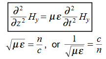
For example, the same equation is true for  and
and  . Thus,
  and
and  must have the same type of functional dependence. This wave equation still has many possible solutions. In fact, it can be shown by direct substitution that

Are the solutions

t is important to note that f1 and f2 can be any function.
The field we find directly from the equation:

Suppose
 …………(3)
Differentiate (3) with respect to z
 …………(4)
Integrate with respect to time
 …………(5)

This leads to a new quantity that relates the electric and magnetic fields:


Rewriting:
Units of  =
=  =
=  = Ω
= Ω
 0= Impedance of free space =
  =377Ω
=377Ω
 = impedance of a lossless dielectric =
  =
= =
= 
Note that  and
and  are in time phase and space quadrature
The directions of the vectors are such that:

This vector  , always points in the direction of propagation. These types of waves are called Uniform Plane Electromagnetic Waves.
“Plane” refers to the fact that, at any instant in time, the surfaces of constant phase are planes (here, constant).
“Uniform” means no variation in transverse direction.The wave derived here is one oscillating at a single frequency. The frequency is determined by the source. If the source has multiple frequencies, so will the wave. In communications, modulating a carrier wave results in multiple frequencies. But before we can study such fields, we must thoroughly understand single frequency sinusoidal waves.
Maxwell’s four equations in dielectric mediumare given by
∇·E = ρ/ε0 (1)
∇×E = −∂B/∂t (2)
∇×H = J + ∂D/∂t (3)
∇·B = 0 (4)
These equations illustrate the unique coexistence in nature of the electric field and the magnetic field. The first two equations give the value of the given flux through a closed surface, and the second two equations give the value of a line integral around a loop. In this notation,
∇=(∂/∂x, ∂/∂y, ∂/∂z)
E is the electric vector
B is the magnetic induction
ρ is the electric charge density
j is the electric current density
ε0 is the permittivity of free space
c is the speed of light.
In addition to Maxwell equations, the following identities are useful:
J = σE (5)
D = εE (6)
B = μH (7)
Here,
D is the electric displacement
H is the magnetic vector
σ is the specific conductivity
ε is the dielectric constant (or permittivity)
μ is the magnetic permeability
For dielectric material, We know that dielectricis non-conducting medium means no current so conductivity is zero i.e. σ=0
So current density J=σE will also become zero as σ=0
Using these the Maxwell equation can rewritten as
∇.D=ρ or ∇·E = ρ/ε0∇.E=0 (12)
∇ x E= -dB/dt or ∇ x E= -μdH/dt because B = μH (13)
∇x H=d D/dt or ∇ x H = εdE/dt (J=0) and D = εE (14)
∇.B=0 (15)
Now taking curl of second Maxwell’s equation (13) ,we get
∇x(∇ x E)=- μd/dt (∇ x H)
Applying standard vector identity, that is [∇ *(∇*E)=∇(∇.E)-∇2E] on left hand side of above equation, we get
∇ (∇ .E)-∇2E= -μd/dt (∇x H) (16)
Substituting equations (13) and (14) in equations (16) ,we get
-∇2E= – μεd/dt (dE/dt)
Or ∇2E=με d 2 E/dT2 (17)
Equation (17) is the required wave equation in terms of electric field intensity, E for free space . This is the law that E must obey.
Take curl of fourth Maxwell’s equation (14) ,we get
∇x(∇xH)=ε d/dt(∇xE)
Applying standard vector identity that is
[∇*(∇*H)=∇ (∇.H)-∇2H]
On left side of above equation , we get
∇(∇.H)-∇2H= ε d/dt(∇xE) (18)
Substituting equations (14) and (13) in equation(18) ,we get
-∇2H= – μεd/dt(dH/dt)
Or
∇2H=με d2H/dt2 (19)
Equations (19) is the required wave equation in terms of magnetic field intensity, H and this is the law that H must obey
The general wave equation for a wave

(x,t) traveling in the x direction with speed v. Equating the speed with the coefficients, we derive the speed of electric and magnetic waves, which is a constant that we symbolize with “c”
On comparing, we get
c2=1/εμ
So velocity of the wave is dielectric medium is given by
c = 1/
Let us rewrite the equation (17) and (19) for one dimension.
Or d 2 E/dx2 =με d 2 E/dt2 (20)
d2H/dx2= μεd2H/dt2 (21)
It is useful to note that in vacuum
c2=1/ε0μ0
Where μ0 is the permeability of free space

The velocity of the wave in free space is a constant and approximately equal to the 3x10⁸ms-1which is identical with the speed of light. This implies that light wave is em wave. Both the electric and magnetic fields satisfy the same wave equation. In other words, the oscillations of both the electric as well as magnetic fields are in phase with each other.
The electric and magnetic fields waves are non-dispersive in vacuum or free space because c =3x10⁸ms-1is same for all wavelengths.
PROPAGATION OF ELECTROMAGNETIC WAVES IN A CONDUCTING MEDIUM
We will consider a plane electromagnetic wave travelling in a linear dielectric medium such as air along the z direction and being incident at a conducting interface. The medium will be taken to be a linear medium. So that one can describe the electrodynamics using only the E and H vectors. We wish to investigate the propagation of the wave in the conducting medium.
As the medium is linear and the propagation takes place in the infinite medium, the vectors  ,
,  and
and  are still mutually perpendicular. We take the electric field along the x direction, the magnetic field along the y-direction and the propagation to take place in the z direction. Further, we will take the conductivity to be finite and the conductor to obey Ohm’s law,
  =𝜎
=𝜎 . Consider the pair of curl equations of Maxwell.

Let us take ,
,  and
and  to be respectively in x, y and z direction. We thenhave,
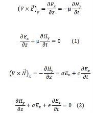
We take the time variation to be harmonic ( ~𝑒𝑖ωt ) so that the time derivative is equivalent to a multiplication by 𝑖ω. The pair of equations (1) and (2) can then be written as

We can solve this pair of coupled equations by taking a derivative of either of the equations with respect to z and substituting the other into it,

Define, a complex constant γ through

In terms of which we have,

Similarly, we get

Solutions of (3) and (4) are well known and are expressed in terms of hyperbolic functions,

Where A, B, C and D are constants to be determined. If the values of the electric field at z=0 is 𝐸0 and that of the magnetic field at z=0 is 𝐻0, we have 𝐴=𝐸0 and 𝐶= 𝐻0.
In order to determine the constants B and D, let us return back to the original first order equations (1) and (2)

Substituting the solutions for E and H

This equation must remain valid for all values of z, which is possible if the coefficients of sinhand cosh terms are separately equated to zero,

The former gives,
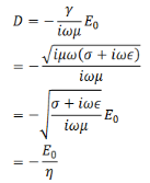
Where

Likewise, we get,

Substituting these, our solutions for the E and H become,

The wave is propagating in the z direction. Let us evaluate the fields when the wave has reached z = 𝑙,

If 𝑙 is large, we can approximate

We then have,

The ratio of the magnitudes of the electric field to magnetic field is defined as the “characteristic impedance” of the wave

Suppose we have lossless medium, σ=0, i.e. for a perfect conductor, the characteristic impedance is

If the medium is vacuum, μ = μ0 = 4π x 10-7 N/A2 and 𝜖= 𝜖0 = 8.85 × 10⁻¹² C2/N - m2gives 𝜂 ≈ 377 𝛺. The characteristic impedance has the dimension of resistance.
In this case, 𝛾= 𝑖 .
.
Let us look at the full three dimensional version of the propagation in a conductor. Once again, we start with the two curl equations,

Take a curl of both sides of the first equation,

As there are no charges or currents, we ignore the divergence term and substitute for the curl of H from the second equation,
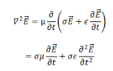
We take the propagating solutions to be

So that the above equation becomes,

So that we have, the complex propagation constant to be given by

So that

k is complex and its real and imaginary parts can be separated by standard algebra,
We have

Thus the propagation vector β and the attenuation factor α are given by
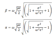
The ration  determines whether a material is a good conductor or otherwise. Consider a good conductor for which 𝜎≫ω𝜖. For this case, we have,

The speed of electromagnetic wave is given by

The electric field amplitude diminishes with distance as 𝑒-az. The distance to which the field penetrates before its amplitude diminishes be a factor 𝑒−1 is known as the “skin depth” , which is given by

The wave does not penetrate much inside a conductor. Consider electromagnetic wave of frequency 1 MHz for copper which has a conductivity of approximately 6 × 10⁷𝛺-1m-1. Substituting these values, one gets the skin depth in Cu to be about 0.067 mm. For comparison, the skin depth in sea water which is conducting because of salinity, is about 25 cm while that for fresh water is nearly 7m. Because of small skin depth in conductors, any current that arises in the metal because of the electromagnetic wave is confined within a thin layer of the surface.
The penetration depth is commonly called the skin depth δ in this limit (σ>>ωε), where:
Penetration depth is a measure of how deep light or any electromagnetic radiation can penetrate into a material. It is defined as the depth at which the intensity of the radiation inside the material falls to 1/e (about 37%) of its original value at (or more properly, just beneath) the surface.
When electromagnetic radiation is incident on the surface of a material, it may be (partly) reflected from that surface and there will be a field containing energy transmitted into the material. This electromagnetic field interacts with the atoms and electrons inside the material. Depending on the nature of the material, the electromagnetic field might travel very far into the material, or may die out very quickly. For a given material, penetration depth will generally be a function of wavelength.
Skin Depth/Penetration depth
We know that amplitude of the em wave decreases exponentially with distance of penetration of the wave. Suppose, the amplitude at a depth x is denoted by Ex.
Then Ex = E0e-kx ………….(1)
Where k = [ ] ………….(2)
The decrease in amplitude or attenuation of the field vector is quantitatively expressed in terms of a quantity called skin depth.
It is defined as the distance beyond the surface of the conductor inside it at which the amplitude of the field vector is reduced to 1/e of its value at the surface.
Let the skin depth is denoted by  , Then:
Eδ =  E0 ………….(3)
WhereE0 = amplitude vector at the surface of the conductor
Eδ=amplitude of electric vector at depth 
So equation (3) can be written as
 =
=  = e-1
= e-1
 = e-1
= e-1
 e-1
e-1
k =1
=1
 =
= 
It shows that the skin depth varies inversely as the square root of conductivity of the medium and frequency of em wave.
Example:Calculate the skin depth for a frequency of 1010 Hz for silver. Given that  =2 x 10⁷ Sm-1 and 4π x 10-7 m-1
Solution:
 =
= 
 =
= 
 =
=
 =1.125
 m.
m.
Example:Find the skin depth of copper if  =5.8 x 10⁷ Sm-1 and
  = 1.26
 H per meter and n =50 Hz.
Solution:
Given  =5.8 x 10⁷ Sm-1
 = 1.26x 10⁻⁶ Hm-1
n =50 Hz
ω = 2πn =2 x 3.14 x 50 = 314.3
 =
= 
 =
=  =
= = 9.33mm