UNIT 3
Projections of Regular Solids
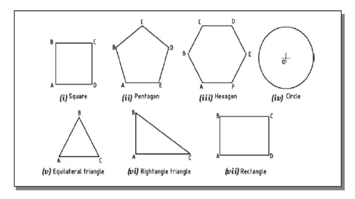
A plane is a two dimensional object having length and breadth only. Its thickness is always neglected. Various shapes of plane figures are considered such as square, rectangle, circle, pentagon, hexagon, etc.
PROJECTIONS OF PLANES
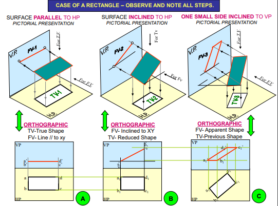
- To draw their projections means F.V, T.V. & S.V.
What will be given in the problem?
- Description of the plane figure.
- It’s position with HP and VP.
In which manner it’s position with HP & VP will be described?
- Inclination of it’s SURFACE with one of the reference planes will be given
- Inclination of one of it’s EDGES with other reference plane will be given (Hence this will be a case of an object inclined to both reference Planes.)
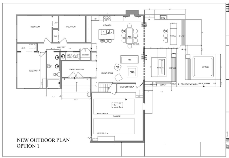
Drawing of a component, in addition to providing complete shape description, must also furnish information regarding the size description. These are provided through the distances between the surfaces, location of holes, nature of surface finish, type of material, etc. The expression of these features on a drawing, using lines, symbols, figures and notes is called dimensioning.
Principles of Dimensioning
Some of the basic principles of dimensioning are given below.
1. All dimensional information necessary to describe a component clearly and completely shall be written directly on a drawing.
2. Each feature shall be dimensioned once only on a drawing, i.e., dimension marked in one view need not be repeated in another view.
3. Dimension should be placed on the view where the shape is best seen (Fig.3.2.1 )
4. As far as possible, dimensions should be expressed in one unit only preferably in millimeters, without showing the unit symbol (mm).
5. As far as possible dimensions should be placed outside the view (Fig. 3.2.2).
6. Dimensions should be taken from visible outlines rather than from hidden lines (Fig. 3.2.3).
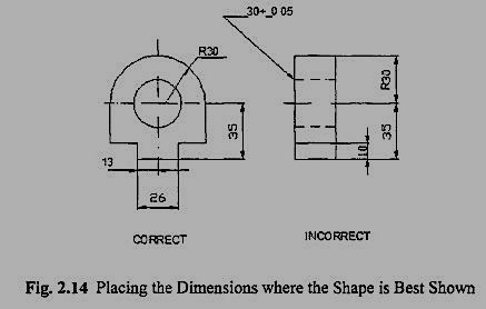
Figure 3.2.1
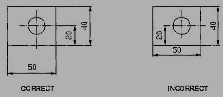
Figure 3.2.2
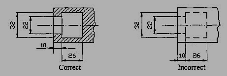
Figure 3.2.3
7. No gap should be left between the feature and the start of the extension line (Fig 3.2.4).
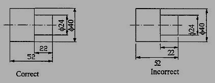
Figure 3.2.4 Marking of Extension lines
8. Crossing of center lines should be done by a long dash and not a short dash (Fig.3.2.5).
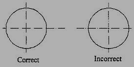
Figure 3.2.5 Crossing of Centre lines
Execution of dimensions:
1. Projection and dimension lines should be drawn as thin continuous lines. Projection lines should extend slightly beyond the respective dimension line. Projection lines should be drawn perpendicular to the feature being dimensioned. If the space for dimensioning is insufficient, the arrow heads may be reversed, and the adjacent arrow heads may be replaced by a dot (Fig.3.2.6). However, they may be drawn obliquely, but parallel to each other in special cases, such as on tapered feature (Fig.3.2.7).
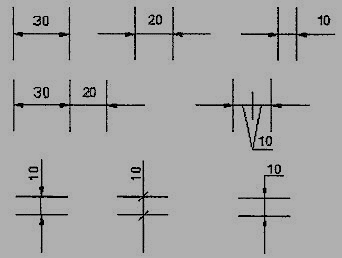
Figure 3.2.6 Dimensioning in narrow spaces

Figure 3.2.7 dimensioning a tapered feature
2. A leader line is a line referring to a feature (object, outline, and dimension). Leader lines should be inclined to the horizontal at an angle greater than 30°. Leader line should terminate,
(a) With a dot, if they end within the outline of an object (Fig.3.2.8a).
(b) With an arrow head, if they end on outside of the object (Fig.3.2.8 b).
(c) Without a dot or arrow head, if they end on dimension line (Fig.3.2.8c).

Figure 3.2.8 Termination of leader lines
Dimension Termination and Origin Indication
Dimension lines should show distinct termination in the form of arrow heads or oblique strokes or where applicable an origin indication (Fig.3.2.9). The arrow head included angle is 15°. The origin indication is drawn as a small open circle of approximately 3 mm in diameter. The proportion length to depth 3: 1 of arrow head is shown in Fig.3.2.10.
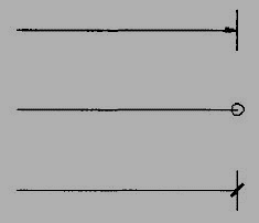
Figure 3.2.9 Termination of dimension lines
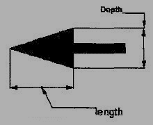
Figure 3.2.10 Proportions of an arrow head
Methods of Indicating Dimensions
The dimensions are indicated on the drawings according to one of the following two methods.
Method I (Aligned method)
Dimensions should be placed parallel to and above their dimension lines and preferably at the middle, and clear of the line. (Fig. 3.2.11).
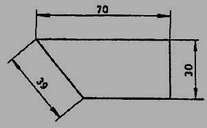
Figure 3.2.11
Dimensions may be written so that they can be read from the bottom or from the right side of the drawing. Dimensions on oblique dimension lines should be oriented as shown in Fig.3.2.12a and except where unavoidable, they shall not be placed in the 30° zone. Angular dimensions are oriented as shown in Fig.3.2.12b.
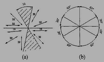
Figure 3.2.12 Angular dimensioning
Method 2(Unit-directional method)
Dimensions should be indicated so that they can be read from the bottom of the drawing only. On-horizontal dimension lines are interrupted, preferably in the middle for insertion of the dimension (Fig.3.2.13a).
Angular dimensions may be oriented as in Fig.3.2.13b

Figure 3.2.13 Uni-directional method
Simple Geometrical constructions
Engineering drawing consists of many geometrical constructions. A few methods are illustrated here without mathematical proofs.
1. To divide a straight line into a given number of equal parts say 5.
Construction (Fig. 3.2.14 )
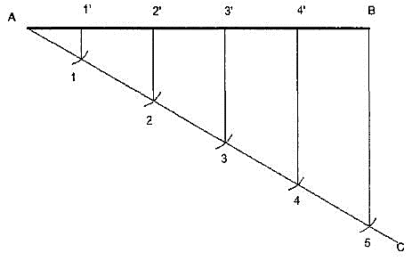
Figure 3.2.14 dividing a line
I. Draw AC at any angle θ to AB.
Ii. Construct the required number of equal parts of convenient length on AC like 1, 2, and 3.
Iii. Join the last point 5 to B
Iv. Through 4, 3, 2, 1 draw lines parallel to 5B to intersect AB at 4', 3’, 2’ and 1'.
2. To divide a line in the ratio 1: 3: 4.
Construction (Fig. 3.2.15)
As the line is to be divided in the ratio 1:3:4. It must be divided into 8 equal divisions. By following the previous example divide AC into 8 equal parts and obtain P and Q to divide the line AB in the ratio 1:3:4.
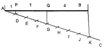
Figure 3.2.15
3. To bisect a given angle.
Construction (Fig. 3.2.16)
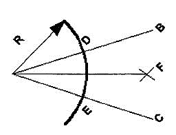
Figure 3.2.16
1. Draw a line AB and AC making the given angle.
2. With center a and any convenient radius R draws an arc intersecting the sides at D and E.
3. With centers D and E and radius larger than half the chord length DE, draw arcs intersecting at F.
4. Join AF, <BAF = <PAC.
i) Introduction to scales & scale factor (RF)
Scales
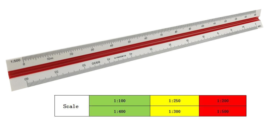
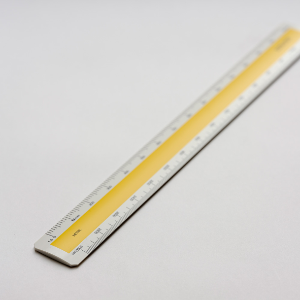
Scales, are made in various number of graduations to meet the requirements of many kinds of work. For convenience, scales are classified according to their most-common uses.
Mechanical Engineers Scale:
These are divided and numbered in such a way that fractions of inches represent inches. The most common ranges are 1/8, 1/4, 1/2, and 1 in. To the inch. These scales are known as the size scales because the reduced size also represents the ratio of size, as for example one-eighth size.
Mechanical engineer's scales are almost always "full divided"; that is, the smallest divisions run throughout the entire length.
They are generally graduated with the marked divisions numbered from right to left, as well as from left to right, as shown in Figure Mechanical engineer's scales are used mostly for drawings of machine parts and small structures where the drawing size is more than one-eighth the size of the actual object.
Civil Engineers Scale:
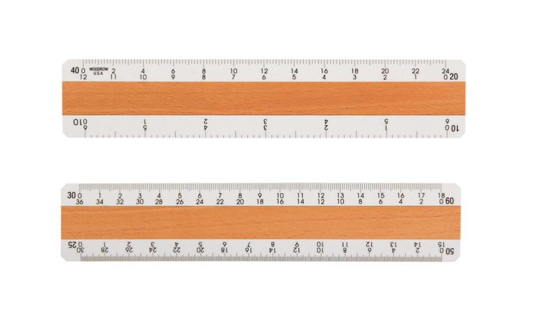
These are divided into decimals with divisions ranging from 10, 20, 30, 40, 50, 60, and 80 to the inch. Such a scale is usually full divided and is sometimes numbered both from left to right and right to left. Civil engineer's scales are most used for plotting and drawing maps, although they are convenient for any work where divisions of the inch in tenths is required.
Metric Scales:
Metric scales are supplied in all the styles and sizes and materials of other scales. They are usually full-divided and are numbered in meters, centimeters, or millimeters depending upon the reduction in size. Typical size reductions are: 1:1, 1:2, 1:5, 1:10, 1:20, 1:25, 1:33.3, 1:50, 1:75, 1:80, 1: 100, 1: 150. Also available are metric equivalent scales for direct conversion of English scales.
