UNIT 6
Overview of Computer Graphics
Graphic communication as the name suggests is communication using graphic elements. These elements include symbols such as glyphs and icons, images such as drawings and photographs, and can include the passive contributions of substrate, color and surroundings. It is the process of creating, producing, and distributing material incorporating words and images to convey data, concepts, and emotions.
The field of graphic communications encompasses all phases of the graphic communications processes from origination of the idea (design, layout, and typography) through reproduction, finishing and distribution of two- or three-dimensional products or electronic transmission.
CAD uses four basic elements for preparation of any drawing:
1. Line
2. Curves
3. Text
4. Filling point.
Computer Aided Drafting is done by the operator by placing the mouse pointer by placing the mouse pointer at the desired location and then executing the command to draw the graphic elements using different methods.
Advanced computer aided drafting packages utilize four areas on the screen.
1. Drawing Area
2. Command Area
3. Menu Area
4. Tool boxes.
LINE: A line is specified by giving its two end points or first point and the distance of line along with its angle of inclination. A line can be drawn by using two commands. Command: line Specify first point: Specify a point
(1) Specify next point or [Undo]: Specify a point
(2) The second point can be indicated by @d.
LAYOUT AND SKETCHING
The package provides various facilities for layout, sketching and borders for preparing a drawing. It provides facilities for display co-ordinates and measurement units.
a. Units: The format for display co – ordinates and measurement can be selected according to the requirement. Several measurement styles are available in ACAD. The main methods are engineering and architectural, having specific base unit assigned to them.
i. Decimal: select to enter and display measurements in decimal notation
Ii. Engineering: Display measurements in feet and decimal inches.
Iii. Architectural: Display measurements in feet, inches and fractional inches
Iv. Fractional: Display measurements in mixed numbers notation
v. Scientific: Display measurements in scientific notation. The precision that is specified controls the number of decimal places or fractional size to which we want linear measurements displayed.
b. Angles: Select the format in which we want to enter and display angles.
i. Decimal Degrees: Display partial degrees as decimals
Ii. Deg/Min/Sec: Display partial degrees as minutes and seconds.
Iii. Grades: Display Angles as grades
Iv. Radians: Display angles as radians.
v. Surveyor: Displays angles in surveyor units.
c. Angle measure: Select the direction of the zero angle for the entry of angles:
i. East: Select to specify the compass direction east as the zero angle.
Ii. North: Select to specify the compass direction north as the zero angle.
Iii. West: Select to specify the compass direction west as the zero angle.
Iv. South: Select to specify the compass direction south as the zero angle.
v. Other: Select to specify a direction different from the points of the compass as the zero angles.
d. Area: Enter the approximate width and length which is planned to draw in full scale units. This limits the area of the drawing covered by grid dots when the grid is turned on. It also adjusts several default settings, such as text height, line type scaling and snap distance to convenient values. It is possible to adjust these settings.
Title block: Select the description of an ACAD drawing file of a title block to insert as a symbol in the new drawing. It can add or remove drawing files of title blocks from the list with the Add or Remove buttons
Layout: Paper space is often used to create complex multiple view drawings. There are three types of paper spaces:
1. Work on the drawing while viewing the layout.
2. Work on the drawing without the layout visible
3. Work on the layout of the drawing. The following procedure is used for this purpose
1. From the File menu or from the standard tool bar, choose New
2. In the start-up dialog box, choose Use a wizard, and select Advanced wizard
3. Choose OK
4. In the Advanced Setup Dialog box, Select Title Block.
5. Select Title Block Description and Title Block file Name from the lists and then choose Add.
6. In the Select Title Block File dialog box, Select a title block, then choose open
7. In the Advanced Setup dialog box, a sample of that title is displayed.
8. Choose Done.
ERASING OF OBJECT: The object can be removed or erased by use of erase command ERASE This removes object from drawing At the command prompt, enter erase Select objects: use an object selection method.
ZOOM: This increases or decreases the apparent size of objects in the current view port At the command prompt,
Enter zoom All/center/dynamic/extents/left/previous/vmax/window/:enter an option or value ,specify a point ,or press enter
TRANSFORMATIONS: These are the modifications in the drawn objects. There are different types of transformations used
1. MOVE: This allows to move or displace objects a specified distance in a specified direction
At the command prompt, enter move Select objects: use an object selection method Base point or displacement: specify a base point
(1) Second point of displacement: specify a point
(2) or press enter
2. COPY: This is used for producing a duplicate copy of the drawing. At the command prompt, enter copy Select objects: use an object selection method /multiple: specify a base point
(1) For a single copy or enter m for multiple copies
3. ROTATE: It moves objects about a base point At the command prompt, enter rotate Select objects: use an object selection method /reference: specify an angle or enter r.
4. STRETCH: This moves or stretches objects .AutoCAD stretches lines, arcs, elliptical arcs, splines, rays and polyline segments that cross the selection window. At the command prompt, enter stretch Select objects: use the CPOLYGON or cross object selection method
(1,2) Base point or displacement: specify a point
(3) or press Second point of displacement: specify a point ($) or press
5. EXTEND: This extends an object to meet another object. Objects that can be extended include arcs, elliptical arcs, lines, open 2D, and 3Dpolylines and rays. At command prompt, enter extend
DIMENSIONING IN DRAWINGS: The dimensions are inserted in the drawing by use of DIM command. There are various types of dimensions used in AutoCAD.
Linear dimensions: Horizontal- this allows horizontal dimensions Vertical- this allows vertical dimensions Aligned- this allows inclined dimensions Rotated- this allows inclined dimensions
Angular dimensions: This allows angular dimensioning of objects
Radial dimensions: This allows radial dimensioning of arc or circle
Diametric dimensions: This allows diameteral dimensions of the circle For dimensioning of objects, the first point and second point has to be specified. The dimension text must be written and then the position of dimension must be specified at the command prompt ,enter dim
Isometric drawing of planes or plane figures:
Problem:
1. The front view of a square is given in fig. 6.2.1 (i). Draw its isometric view.
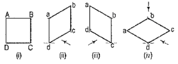
Figure 6.3.1
As the top view is a square, the surface of the square is horizontal. In isometric view, all the sides will be drawn inclined at 30° to the horizontal.
(i) From any point d [fig. 6.3.1 (iv)], draw two lines da and dc inclined at 30° to the horizontal and making 120° angle between themselves.
(ii) Complete the rhombus abed which is the required isometric view.
2. Fig. 6.3.2 (i) shows the front view of a circle whose surface is parallel to the V.P. Draw the isometric view of the circle.
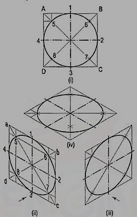
Figure 6.3.2
I. Method of points:
(i) Enclose the circle in a square, touching it in points 1, 2, 3 and 4. Draw the diagonals of the square cutting the circle in points 5, 6, 7 and 8.
(ii) Draw the isometric view of the square [fig. 6.3.2 (ii) and [fig. 6.3.2 (iii)] and on it mark the mid-points 1, 2, 3 and 4 of its sides. Obtain points 5, 6, 7 and 8 on the diagonals.
If the view given in fig. 6.3.2 (i) is the top view of a circle whose surface is horizontal, its isometric view will be as shown in fig. 6.3.2 (iv).
As the isometric views have been drawn with the true scale, the major axis of the ellipse is longer than the diameter of the circle.
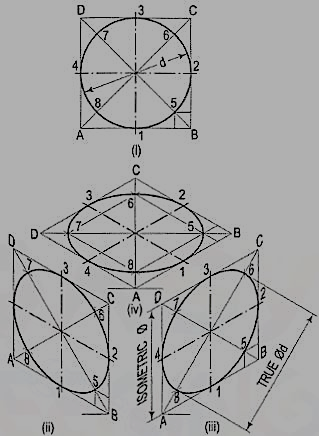
Figure 6.3.3
Fig. 6.3.3 (ii), fig. 6.3.3 (iii) and fig. 6.3.3 (iv) show the isometric projection of the circle drawn with isometric scale. Note that when the length of the side of the rhombus is equal to the isometric diameter of the circle, the length of the major axis of the ellipse is equal to the true diameter of the circle.
II. Four-center method:
Draw the isometric view of the square [fig. 6.3.4 (i)]. Draw perpendicular bisectors of the sides of the rhombus, intersecting each other on the longer diagonal at points p and q, and which meet at the 120°-angles b and d.
Or, draw lines joining the 120°-angles b and d with the mid-points of the opposite sides and intersecting each other on the longer diagonal at points p and q. Two of these lines will be drawn horizontal, while the other two will make 60°-angles with the horizontal. With centres b and d, draw arcs 3-4 and 1-2 respectively. With centres p and q, draw arcs 1-4 and 2-3 respectively and complete the required ellipse. Fig. 6.3.4 (ii) shows the ellipse obtained in the rhombus drawn in the direction of the other sloping axis. Fig. 6.3.4 (iii) shows the isometric view of the circle when its surface is horizontal.
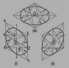
Figure 6.3.4
The ellipse obtained by the four-centre method is not a true ellipse and differs considerably in size and shape from the ellipse plotted through points. But owing to the ease in construction and to avoid the labour of drawing freehand neat curves, this method is generally employed.
Problem:
1. Fig. 6.3.5 (i) shows the front view of a semi-circle whose surface is para1lel to the V.P. Draw its isometric view.
(i) Enclose the semi-circle in a rectangle. Draw the isometric view of the rectangle [fig. 6.3.5 (ii) and [fig. 6.3.5 (iii)].
(ii) Using the four-centre method, draw the half-ellipse in it which is the required view. The centre for the longer arc may be obtained as shown or by completing the rhombus.
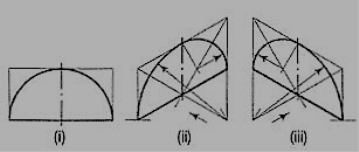
Figure 6.3.5
If the view given in fig. 6.3.6 (i) is the top view of a horizontal semi-circle, its isometric view would be drawn as shown in fig. 6.3.6 (i) and fig. 6.3.6 (ii).
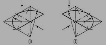
Figure 6.3.6
2. Fig. 6.3.7 (i) shows the front view of a plane parallel to the V.P. Draw its isometric view.
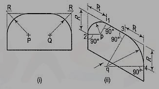
Figure 6.3.7
(i) The upper two corners of the plane are rounded with quarter circles. Enclose the plane in a rectangle.
(ii) Draw the isometric view of the rectangle. From the upper two corners of the parallelogram, mark points on the sides at a distance equal to R, the radius of the arcs. At these points erect perpendiculars to the respective sides to intersect each other at points p and q. With p and q as centres, and radii p1 and q3, draw the arcs and complete the required view.