UNIT 3
PLANAR RIGID BODY MECHANICS
Even though a rigid body is composed of an infinite number of particles, the motion of these particles is constrained to be such that the body remains a rigid body during the motion. In particular, the only degrees of freedom of a 2D rigid body are translation and rotation.
- Translation, rectilinear and curvilinear: Motion in which every line in the body remains parallel to its original position. The motion of the body is completely specified by the motion of any point in the body. All points of the body have the same velocity and same acceleration.
- Rotation about a fixed axis: All particles move in circular paths about the axis of rotation. The motion of the body is completely determined by the angular velocity of the rotation.
- General plane motion: Any plane motion that is neither a pure rotation nor a translation falls into this class. However, as we will see below, a general plane motion can always be reduced to the sum of a translation and a rotation.
Motion Relative to Translating Axes
Particle motion has been described using position vectors that were referred to fixed reference frames. The positions, velocities and accelerations determined in this way are referred to as absolute. Often it isn’t possible or convenient to use a fixed set of axes for the observation of motion. Many problems are simplified considerably by the use of a moving reference frame.
In the following we will restrict our attention to moving reference frames that translate but do not rotate.
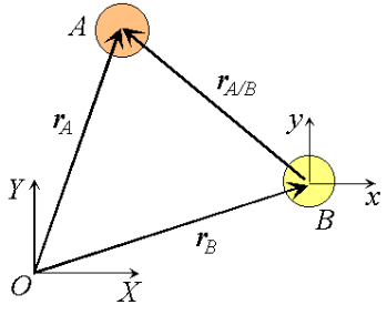
Figure 1: Observation of particle motion using a translating reference.
Consider two particles A and B moving along independent trajectories in the plane, and a fixed reference O. Let rA and rB be the positions of particles A and B in the fixed reference. Instead of observing the motion of particle A relative to the fixed reference as we have done in the past, we will attach a non-rotating reference to particle B and observe the motion of A relative to the moving reference at B. Let i and j be basis vectors of the moving reference, then the position vector of A relative to the reference at B, denoted rA/B is,
rA/B =xi +yj
Where the subscript stands for "A with respect to B" or "A relative to B". Observe that, as the moving frame does not rotate, basis vectors i and j do not change in time. Therefore, taking time derivatives, we obtain simply,


Which can be interpreted as the velocity of A relative to B. Now we can express the absolute position vector of A as,

Differentiating the equation in time to obtain expressions for the absolute velocity and acceleration of particle A:

Or the absolute velocity of A equals the absolute velocity of B plus the velocity of A relative to B, vA/B , and similarly for the acceleration. The relative terms are the velocity or acceleration measured by an observer attached to the moving reference at particle B.
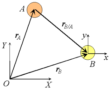
Figure 2: Relative velocities under change of translating reference.
What would happen if the moving reference were attached to A instead?

By comparison with expressions derived previously

We proceed by demonstrating that every motion of a planar rigid body is associated with a single angular velocity ω and angular acceleration , describing the angular displacement of an arbitrary line inscribed in the body relative to a fixed direction.
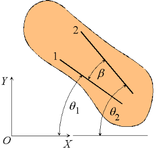
Figure 3: Angular velocity and acceleration of a rigid body.
Consider a rigid body undergoing plane motion. The angular positions of two arbitrary lines 1 and 2 attached to the body are specified by  1and
1and  2 measured relative to any convenient fixed reference direction. These are related to the intermediate angle
  shown as,
 2 =
2 =  1
1
Observe that as the body is rigid, requiring that the distance between each pair of points on the two lines 1 and 2 is constant, angle  must be invariant. Differentiating the relation above with this in mind,

These hold for arbitrary lines attached to the body, implying in turn that the body can be associated with a unique angular velocity ω, defined as,

For an arbitrary line attached to the body. Arguing analogously, the body can be associated with a unique angular acceleration  defined as,

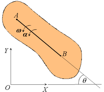
Figure 4: Angular velocity and angular acceleration of a rigid body.
Consequently, we have the property that all lines on a rigid body in its plane of motion have the same angular displacement, the same angular velocity ω and the same angular acceleration. 
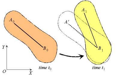
Figure 5: Decomposition of rigid body motion.
Next, consider the motion of a rigid body over the interval t0 - t1 as shown, with arbitrary point B0 taken as reference. Clearly, the motion can be consider to occur in two stages: a translation with reference B0 taking arbitrary line A0 B0 to an intermediate position A’B1; and a rotation about point B1 taking A’B1 to its final position A1B1. This corresponds to a decomposition of the motion into the sum of a translation and a rotation. While the translational motion is described by the velocity  and acceleration
  of the reference point, the rotational motion is characterized by the unique angular velocity ω and angular acceleration
  associated with the body. Thus, we have the property that the motion of a rigid body can be decomposed into a translation of an arbitrary point within the body, followed by a rigid rotation of the body about this point. Further, the motion of an arbitrary point within the body is determined completely once the translational quantities
  and
and  and rotational quantities ω and
  are known.
Characteristics of rigid body motion:
- All lines on a rigid body have the same angular velocity ω and the same angular acceleration
 .
. - Rigid motion can be decomposed into the translation of an arbitrary point, followed by a rotation about the point.
Now we will derive equations that describe the motion.
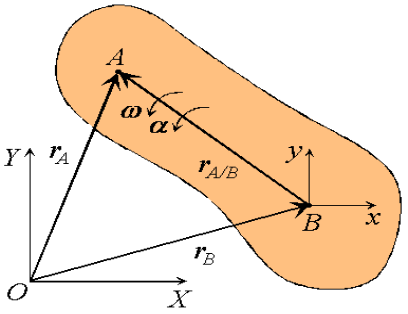
Figure 6: Definition of a translating reference attached to point B.
Consider a rigid body moving in the plane with angular velocity ω and angular acceleration  , and two arbitrary points A and B of the body. We will examine the motion of this body in both, the fixed reference O shown, as well as relative to a non-rotating reference attached to point B. Proceeding, we express the absolute position of point A in terms of the absolute position of point B as,

Where rA/B is the position of A relative to B. An analogous expression for absolute velocities follows by taking time derivatives,

Where vA/B is the velocity of point A relative to the reference at B,

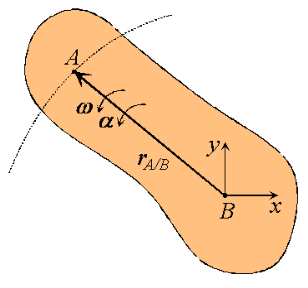
Figure 7: Motion of point A as seen by a translating observer at B.
Now, as the body moves, point A traces a circular path of radius rA/B =  relative to point B, keeping the distance between the two unchanged. The angular velocity of this motion is simply the angular velocity ω of the rigid body. Then, using results derived previously for the time derivatives of rotating vectors we have:

Or,

Observe that the expression reflects the decomposition of rigid body motion referred to previously. With B chosen as reference, the velocity of A is the vector sum of a translational portion vB and a rotational portion ω rA/B .
Proceeding to derive expressions for the acceleration of an arbitrary point of a rigid body, we differentiate the equation for velocities to obtain,

Where  A/B , the acceleration of point A relative to the reference at B, is simply

Or,

Thus, like the absolute velocity, the absolute acceleration of point A is the vector sum of a translational portion  B and a rotational portion
  .
.
When all parts of a rigid body move parallel to a fixed plane, then the motion of the object is referred to as plane motion. There are two types of plane motion, which are given as follows:
The pure rotational motion: The rigid body in such a motion rotates about a fixed axis that is perpendicular to a fixed plane. In other words, the axis is fixed and does not move or change its direction relative to an inertial frame of reference.
The general plane motion: The motion here can be considered as a combination of pure translational motion parallel to a fixed plane in addition to a pure rotational motion about an axis that is perpendicular to that plane.
Suppose a rigid body of an arbitrary shape is in pure rotational motion about the z-axis (see Figure 8). Let us analyze the motion of a particle that lies in a slice of the body in the x-y plane as in Figure 9. This particle (at point P) will rotate in a circle of fixed radius r which represents the perpendicular distance from P to the axis of rotation. If you look at any other particle in the object you will see that every particle will rotate in its own circle that has the axis of rotation at its center. In other words, different particles move in different circles but the center of all of these circles lies on the rotational axis. Suppose the particle moves through an arc length s starting at the positive x-axis. Its angular position is then given by
θ=s/r
r and θ are the polar coordinates of a point in a plane where θ is always measured from the positive x-axis. Because θ is the ratio of the arc length to the radius, it is a pure (dimensionless) number.
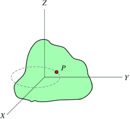 | 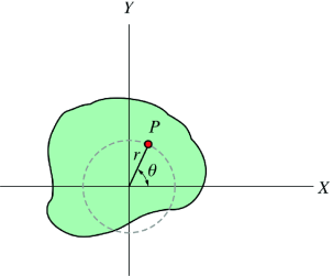 |
Figure 8:A rigid body of an arbitrary shape is in pure rotational motion about the z-axis
| Figure 9: The motion of a particle that lies in a slice of the body in the x-y plane
|
When a rigid body moves in such a way that one point in it remains fixed, then motion of the rigid body is called rotation about a point. The point which remains fixed during motion is called the centre of rotation.
Consider a body which is rotating about a point O. All the particles of the body will rotate about it. Since the body is rigid, the distance between all pairs remains fixed during the motion. Let us consider a particles P of the rigid body having position vector  . Let b be its distance from the origin O. The rigidity condition requires that
 = b
= b
Where b is constant.
Squaring the above both sides we obtain
 =
= 
 .
. =
=
Differentiate both sides with respect to time to obtain
 .
. +
+
 = 0
= 0
 .
. +
+
 = 0
= 0
 .
. = 0
= 0
This equation shown that whenever a rigid body rotates about a fixed point, the instantaneous velocity vector of any particle is always perpendicular to its instantaneous position vector.
Kinetic energy of rigid body in rotation
Kinetic energy of a particle or body represents the form of energy that arises from motion. We are aware that kinetic energy of a particle in translation is given by the expression:
K= mv2
mv2
In pure rotation, however, the rigid body has no "over all" translation of the body. However, the body in rotation must have kinetic energy as it involves certain motion. A closer look on the rotation of rigid body reveals that though we may not be able to assign translation to the rigid body as a whole, but we can recognize translation of individual particles as each of them rotate about the axis in circular motion with different linear speeds. The speed of a particle is given by:
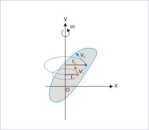
Figure 10
Pure rotational motion Each particle of the body follows a circular path about axis in pure rotational motion.
vi= ωri
Thus, kinetic energy of an individual particle is :
Ki= mivi2
mivi2
Where " Ki" is the kinetic energy of "i" th particle having a speed " vi". In terms of angular speed, the kinetic energy of an individual particle is:
Ki= mi(ωri2
Ki= mi(ωri)2
Now, the kinetic energy of the rigid body is sum of the kinetic energies of the particles constituting the rigid body:
K=∑Ki=∑ mi(ωri)2
We note here that angular speeds of all particles constituting the body are same. Hence, the constant "1/2" and " ω2" can be taken out of the summation sign :
K = ω2∑mi(ri)2
However, we know that:
I=∑mi(ri)2
Combining two equations, we have:
K=  Iω2
Iω2
This is the desired expression of kinetic energy of a rigid body rotating about a fixed axis i.e. in pure rotational motion. The form of expression of the kinetic energy here emphasizes the correspondence between linear and angular quantities. Comparing with the expression of kinetic energy for translational motion, we find that "moment of inertia (I)" corresponds to "mass (m)" and "linear speed (v)" corresponds to "angular speed (ω)".
We can also interpret the result obtained above from a different perspective. We could have directly inferred that expression of kinetic energy in rotation should have an equivalent form as:
K (Kinetic energy)=  x(inertia)x(speed)2
In rotation, inertia to the rotation is "moment of inertia (I)" and speed of the rigid body is "angular speed (ω)". Substituting for the quantities, we have the expression for kinetic energy of rigid body in rotation as :
K=  Iω2
Iω2
Comparing this equation with the expression of the sum of kinetic energy of individual particles as derived earlier:
K = ω2∑mi(ri)2
Clearly,
I= ∑mi(ri)2
This conclusion, thus, clearly establishes that the expression as given by ∑mi(ri)2
Indeed represents the inertia of the rigid body in rotation
Consider a rigid body which a rotating about a fixed point with an angular velocity  . Choose the origin O at the fixed point and axes as shown in Figure 11
The velocity of particle i having position vector is
is
 =
= 

 …………(1)
If mi is the mass of particle i then its angular momentum about the fixed point O is
 =
= 
 …………(2)
Substituting the value of  , it takes the form
 =
= 


 …………(3)
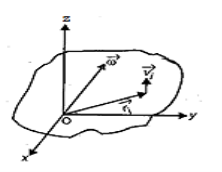
Figure 11
The angular momentum of rigid body can be obtained by summing the above equation over all the particles of the rigid body. Thus
 =
= 
 =
=  …………(4)
Using the vector relation

 …………(5)
Eq. (4) may be written as
 =
= 

 =
= 
 …………(6)
Let (xi, yi, zi) be the cartesian coordinates of particle i, then
 …………(7)
If ωx, ωy and ωz are the components of angular velocity along coordinate axes then
 …………(8)
Now take the dot product of  with
with  to obtain
 .
.  …………(9)
Substitutes these values in eq. (6) to obtain
 =
= 
 =
=  [
[ +
+ 
 +
+  ]
]
 =
=  [
[ +
+ 
 +
+  ]
]
 =
=  +
+  +
+  ] …………(10)
In this expansion it is useful to introduce the following abbreviations.
  |   |  
|
 
|   |  
|
 
|  
|  
|
…………(11)
These nine quantities Ixx, Ixy,….Izy are the components of the moments of intertia of the body about the fixed x,y,z axes. The components Ixx, Iyy and Izz are called the moments of intertia about x-axis, y-axis and z-axis respectively and the components Ixy,Iyz, …., Izy are called the products of intertia. A quantity such as the moment of intertia is called a tensor of second rank.
In terms of the moments of intertia and products of intertia,  may be written as
 =
=  +
+  +
+  )
)
…………(12)
This equation shows that the angular momentum vector  is, in general, not in the direction of angular velocity vector
  or the axis of rotation.
Eq. (11) shows that
 =
=


 …………(13)
Thus the rotational behaviour of a rigid body about a given point it determined by a set of six quantities: the three moments of intertia and the three products of intertia. These moments of intertia and products of intertia will in general be function of time.
Consider a system consisting of a large number of particles. It is almost impossible to clearly describe the motion of each particle, even though their collisions are elastic. So How do we apply our understanding on force, momentum, kinetic and potential energy, and conserved quantities to such a system?
Here we will introduce the new concept “Center of Mass (CM)”.
When the motion of a body involves not only translation but also rotation or vibration or both, we must treat it as a system of particles. Despite the complex motions of which a system is capable, there is a single point, the center of mass(CM), whose translational motion is characteristic of the system as a whole.
In other words we can say that
There is a special point in a system or object, called the centre of mass that moves as if all of the mass of the system is concentrated at that point.
For simple rigid objects with uniform density, the center of mass is located at the centroid. For example, the center of mass of a uniform disc shape would be at its center. Sometimes the center of mass doesn't fall anywhere on the object. The center of mass of a ring for example is located at its center, where there isn't any material.

Figure 12: Center of mass for some simple geometric shapes (red dots).
For more complicated shapes, we need a more general mathematical definition of the center of mass:
It is the unique position at which the weighted position vectors of all the parts of a system sum up to zero.
The concept of Center of Mass (CM) is useful because it makes it easy to solve mechanics problems where we have to describe the motion of oddly-shaped objects and complicated systems. For the purposes of calculation, we can treat an oddly-shaped object as if all its mass is concentrated in a tiny object located at the center of mass. We sometimes call this imaginary object a point mass.
If we push on a rigid object at its center of mass, then
- The object will always move as if it is a point mass.
- It will not rotate about any axis, regardless of its actual shape.
- If the object is subjected to an unbalanced force at some other point, then it will begin rotating about the center of mass.
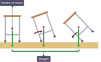
Figure 13
In general the center of mass can be found by vector addition of the weighted position vectors which point to the center of mass of each object in a system. One quick technique which lets us avoid the use of vector arithmetic is finding the center of mass separately for components along each axis.
The system of two particles is given below
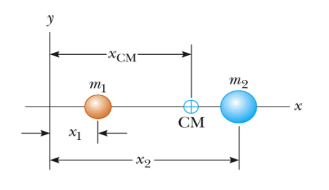
Figure 14
The CM for this system is given by

If we extend the system for N particles to three dimension then position of CM is given by the coordinates
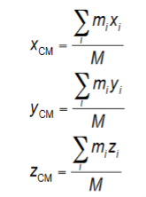
Where M is the total mass of the system. These together give the location of the center of mass of the system.
So the centre of mass in three dimensions can be located by its position vector, 
For a system of particles

 is the position of the ith particle, defined by?

For an extended object,

Center of Mass of Continuous Bodies
To find the center of mass of a continuous body one must integrate the contributions of each mass element dm.
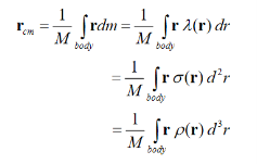
Motion of the Center of Mass
The velocity of the centre of mass of a system of particles is

The momentum can be expressed as

The total linear momentum of the system equals the total mass multiplied by the velocity of the centre of mass. The total momentum of a system of particles is equivalent to that of a single (imaginary) particle of mass M=Σmi moving at the velocity of the center of mass vcm.
Force of the center of mass
The rate of change of the total momentum of a system is equal to the net external force.

If the net external force on a system of particles is zero, the velocity of the center of mass remains constant.
If Fext =0, then vcm = constant
If the net external force on a system of particles is zero, the velocity of the center of mass remains constant.
Center of gravity & Center of mass
The center of gravity is the point through which the force of gravity acts on an object or system. In most mechanics problems the gravitational field is assumed to be uniform. The center of gravity is then in exactly the same position as the center of mass. The terms center of gravity and center of mass tend to often be used interchangeably since they are often at the same location.
A body rotating about an axis resists any change in its rotational motion (angular velocity). On account of this property the body is said to possess a ‘moment of inertia’ or ‘rotational inertia’ about that axis.
“The property of a body by virtue of which it opposes any change in its state of rotation about an axis is called the ‘moment of inertia’ of the body about that axis”.
It is denoted by I.
“The moment of inertia of a particle about an axis is given by the product of the mass of the particle and the square of the distance of the particle from the axis of rotation”.
If a particle of mass m is at a distance r from an axis of rotation, its moment of inertia I about that axis is given as-
I = mr2 …..(19)
Let us consider a rigid body of mass M. We have to find out the moment of inertia about a vertical axis passing through O (Figure 15). If m1, m2, m3, ………be the masses of the particles composing the body and r1, r2, r3, ………their respective distances from the axis of rotation, the moment of inertia I of the body about that axis is equal to the sum of the moments of inertia of all the particles i.e.
I = m1r12 + m2r22 + m3r32 +……… …....(1)
Or I = Σ mr2 …..(2)
Here Σ (sigma) means the sum of all terms.
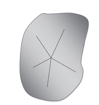
Figure 15
For a body having a continuous distribution of matter,
I = dm …..(3)
Where dm is the mass of an infinitesimally small element of the body taken at a distance r from the axis of rotation. Hence, “the moment of inertia of a rigid body about a given axis is the sum of the products of the masses of its particles by the square of their respective distances from the axis of rotation”.
The unit of moment of inertia is Kg-m2.
Obviously, the moment of inertia of a body about an axis depends not only on the mass of the body but also upon the manner in which the mass is distributed around the axis of rotation.
Radius of Gyration
The radius of gyration of a body about an axis of rotation is defined as the distance of a point from the axis of rotation at which whole mass of the body were assumed to be concentrated, its moment of inertia about the given axis would be the same as with its actual distribution of mass. It is usually denoted by the letter k.
If M is the total mass of the body; its moment of inertia in terms of its radius of gyration k can be written as-
I = M k2 …..(23)
Or k =  …..(24)
Thus “the square root of the ratio of moment of inertia of the body about the given axis of rotation to its mass is called radius of gyration of the body about the given axis”.
Physical significance of Moment of Inertia
According to Newton’s first law of motion, we know that if a body is at rest or moving with a uniform speed along a straight line, then an external force is necessary to change its state. This property of bodies is called ‘inertia’. Greater the mass of a body, greater is the force required to bring a change in its position of rest or in its linear velocity (i.e. to produce linear acceleration in it). In this way, the mass of a body is a measure of its inertia.
Similarly, in order to rotate a body (initially at rest) about an axis or to change the angular velocity of a rotating body (i.e. to produce an angular acceleration in it), a torque has to be applied on the body. This is described by saying that the body has a ‘moment of inertia’ about the axis of rotation. The greater the moment of inertia of a body about an axis, the greater is the torque required to rotate, or to stop, the body about that axis. Thus, the moment of inertia plays the same role in the rotational motion as mass plays in translational motion.
There is a difference between inertia and moment of inertia of a body. The inertia of a body depends only upon the mass of the body. But the moment of inertia of a body about an axis depends not only on the mass of the body but also upon the distribution of its mass about the axis of rotation.
Practical applications of Moment of Inertia
An important use of the property of moment of inertia is made in stationary engines. The torque rotating the shaft of an engine changes periodically and so the shaft cannot rotate uniformly. To keep its rotation uniform, a large heavy wheel is attached with the shaft. This wheel is called ‘flywheel’ and it has a large moment of inertia. As the shaft rotates, the flywheel also rotates. Due to its large moment of inertia, the flywheel (and hence the shaft) continues to rotate almost uniformly in spite of the changing torque. A small flywheel is attached to the bottom of toy- motor. The flywheel is rotated by rubbing it on the ground and the motor is left for running. Due to the moment of inertia of the flywheel, the motor continues moving for some time.
The moment of inertia plays vital role in our daily life. In cycle, rickshaw, bullock-cart, etc., the moment of inertia of the wheels is increased by concentrating most of the mass at the rim of the wheel and connecting the rim to the axle of the wheel through spokes. It is due to the large moment of inertia of the wheels that when we stop cycling, the wheels of the cycle continue rotating for some time.
Moment of inertia of rigid body
Rigid body is a continuous aggregation of particles. We, therefore, need to modify the summation in the expression of moment of inertia by integration as :
I = ∫r2đm
Evaluation of this integral for a given body is a separate task in itself. It is mathematically possible to evaluate this integral for bodies of regular shape. It would, however, be very difficult to evaluate the same for irregularly shaped rigid body. In such cases, it is pragmatic to resort to experimental methods to calculate moment of inertia. Mathematical evaluation of moment of inertia even for regularly shaped bodies would require specialized analysis and evaluation.
Two theorems, pertaining to moment of inertia, are of great help in the mathematical evaluation of moment of inertia of regularly shaped bodies. They are (i) parallel axes theorem and (ii) perpendicular axes theorem. These theorems extend the result of moment of inertia of basic geometric forms of rigid bodies to other axes. There are two important theorems on moment of inertia which, in some cases, facilitate the moment of inertia of a body to be determined about an axis, if its moment of inertia about some other axis be known. Let us discuss these theorems.
Theorem of Parallel Axes
It states that the moment of inertia of a body about any axis is equal to its moment of inertia about a parallel axis through its centre of mass plus the product of the mass of the body and the square of the perpendicular distance between the two axes.
If ‘Icm’ be the moment of inertia of a body about a parallel axis through its centre of mass, ‘M’ be the mass of the body and ‘r’ be the perpendicular distance between two axes, then moment of inertia of the body I = Icm + Mr2
This is the “theorem of parallel axes”.
Proof:
Let us consider a plane lamina with ‘C’ as centre of mass. Let ‘I’ be its moment of inertia about an axis PQ in its plane and Icm the moment of inertia about a parallel axis RS passing through C. Let the distance between RS and PQ be ‘r’.
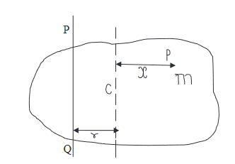
Figure 16
Let us consider a particle P of mass m at a distance x from RS. Its distance from PQ is (r + x) and its moment of inertia about it is m(r + x)2 . Therefore, the moment of inertia of the lamina about PQ is given by-
I = Σ m(r + x)2
= Σ m(r2 + x2 + 2rx)
= Σ mr2 + Σ mx2 + Σ 2mrx
Or I = r2 Σ m + Σ mx2 + 2r Σ mx …..(4)
Since r is constant
But Σ mx2 = Icm, where Icm is the moment of inertia of the lamina about RS, r2 Σm = r2 M where M is the total mass of the lamina and Σmx = 0 because the sum of the moments of all the mass particles of a body about an axis through the centre of mass of the body is zero. Hence, the equation (4) becomes
I = r2 M + Icm + 0
Or I = Icm + M r2 …..(5)
It may be seen clearly from equation (5) that the moment of inertia of a body about an axis through the centre of mass is the least. The moment of inertia of the body about an axis not passing through the centre of mass is always greater than its moment of inertia about a parallel axis passing through the centre of mass of the body.
Theorem of Perpendicular Axes
According to this theorem, the moment of inertia of a uniform plane lamina about an axis perpendicular to its plane is equal to the sum of its moments of inertia about any two mutually perpendicular axes in its plane intersecting on the first axis.
If Ix and Iy be the moments of inertia of a plane lamina about two mutually perpendicular axes OX and OY in the plane of the lamina and Iz be its moment of inertia about an axis OZ, passing through the point of intersection O and perpendicular to the plane of the lamina, then
Iz = Ix + Iy
This is the “theorem of perpendicular axes”.
Proof:
Let OZ be the axis perpendicular to the plane of the lamina about which the moment of inertia is to be taken. Let OX and OY be two mutually perpendicular axes in the plane of the lamina and intersecting on OZ.
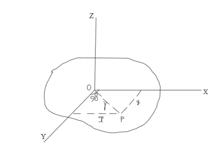
Figure 17
Let us consider a particle P of mass ‘m’ at a distance of ‘r’ from OZ. The moment of inertia of this particle about OZ is mr2. Therefore, the moment of inertia Iz of the whole lamina about OZ
Is Iz = Σ mr2
But r2 = x2 + y2, where x and y are the distances of P from OY and OX respectively.
Therefore, Iz = Σ m(x2 + y2) = Σ mx2 + Σ my2
But Σ mx2 is the moment of inertia Iy of the lamina about OY and Σ my2 is the moment of inertia Ix of the lamina about OX.
Therefore, Iz = Iy + Ix
Or Iz = Ix + Iy
Example: Show that the moment of inertia I of a thin square plate PQRS (Figure) of uniform thickness about an axis passing through the centre O and perpendicular to the plane of the plate is (I1 + I2) or (I3 + I4) or (I1 + I3).
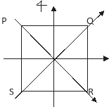
Figure 18
Solution
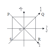
Figure 19
Let I1, I2, I3 and I4 are the moments of inertia about axes 1, 2, 3 and 4 respectively which are in the plane of the plate.
By the theorem of perpendicular axes, we have-
I = I1 + I2 = I3 + I4
By symmetry of square plate, I1 = I2 and I3 = I4
Therefore, I = 2I1 = 2 I3
Or I1 = I3
Thus I1 = I2 = I3 = I4
And I = I1 + I2 = I1 + I3
M.I of a rectangular lamina
(a) About an axis passing through its centre and parallel to breadth
Consider a rectangular lamina ABCD of mass M, length l and breadth b. Let m be its mass per unit area
i.e., m =  , or M = m(l × b).
YY/ is an axis ||el to its breadth. Consider a small strip of thickness dx at a distance x from the axis.
Its mass = m × (b × dx)
M.I of the strip about YY/= mbdx × x2
= mbx2 dx
∴ M.I of the rectangular lamina about YY/ is

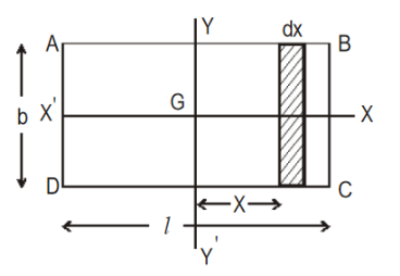
Figure 20


b) Axis Passing through its Centre and parallel to length :
XX/ is an axis passing through its centre and ||el to the length. Consider a small strip of thickness dx at a distance x from the axis.
Its mass = m × (l × dx).
M.I of the strip about XX/ = m l d x × x2
= m l x2 dx
∴ M.I of the rectangular lamina about XX/ is
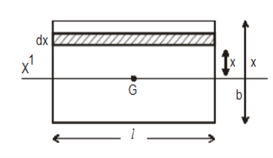
Figure 21


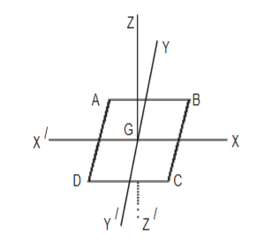
c) Axis Perpendicular to the plane of the lamina and passing through G
According to the theorem of ⊥r axes, M.I of the lamina about an axis ⊥r to the plane of the lamina and passing through G = M.I about two mutually ⊥r axes through G in the plane of the lamina. Let I be the M.I of the lamina about an axis ZGZ/ passing through its CG and ⊥r to its plane.


(d) Axis along one end (AD)


|
| ||
M.I about A  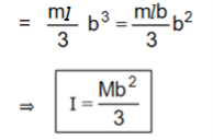 |
|  | |
|
| Figure 22
| |
|
|
| |
e) Axis passing through the mid-point of AD or BC and perpendicular to the plane of the lamina
ABCD is the lamina. Let 0 be the mid-point of AD; let MN be an axis through 0 ⊥r to the plane of the lamina. Let M.I of the lamina about MN be I, YGY/ is a ||el axis through the centre of the lamina and to its plane. Let the M.I of the lamina about Y0Y/ be IG.
Then IG |
|
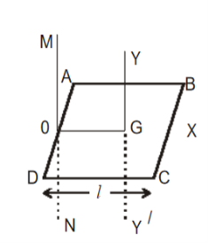 Figure 23
|
 By ||el axes theorem, |
| |
  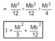 |
|
M.I about an axis through the mid-point of AB or CD and ⊥r to the plane of the lamina

M.I of a circular ring about an axis
a) Through its centre and perpendicular to its plane
Consider a thin circular ring of mass M and radius R. Let Y0Y/ be the axis through its centre and ⊥r to its plane. Consider a small element of mass m. The M.I of this element about Y0Y/ = mR2.
∴ M.I of the ring about Y0Y/, I = ΣmR2. ⇒ I = MR2  R is the distance of each of the elements from 0 | z 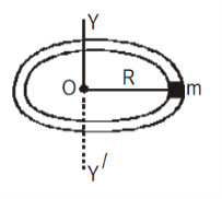 |
Figure 24
b) M.I of the ring about an axis along its diameter
Let X0X/ and Y0Y/ be two axes along two diameters of the ring. Then IX = IY
M.I of the ring is the same about all diameters. Let IX and IY be the M.I of the ring about X0X/ and Y0Y/ respectively. Then IX = IY .
Let the M.I of the ring about an axis through 0 and ⊥r to its plane be I. Then I = ΜR2 where M is the mass and R is the radius of the ring.
By the theorem of ⊥r axes, |  | 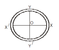
Figure 25
| |
 | |||
 | |||
∴ M.I of the ring about its diameter | 
| ||
The Moment of a force is a measure of its tendency to cause a body to rotate about a specific point or axis. This is different from the tendency for a body to move, or translate, in the direction of the force. In order for a moment to develop, the force must act upon the body in such a manner that the body would begin to twist. This occurs every time a force is applied so that it does not pass through the centroid of the body. A moment is due to a force not having an equal and opposite force directly along its line of action.
Imagine two people pushing on a door at the doorknob from opposite sides. If both of them are pushing with an equal force then there is a state of equilibrium. If one of them would suddenly jump back from the door, the push of the other person would no longer have any opposition and the door would swing away. The person who was still pushing on the door created a moment.
The magnitude of the moment of a force acting about a point or axis is directly proportional to the distance of the force from the point or axis. It is defined as the product of the force (F) and the moment arm (d). The moment arm or lever arm is the perpendicular distance between the line of action of the force and the center of moments.
Moment of a force = Force × Perpendicular distance from the point to force
M = (F)(d)
The Center of Moments may be the actual point about which the force causes rotation. It may also be a reference point or axis about which the force may be considered as causing rotation. It does not matter as long as a specific point is always taken as the reference point.
A moment is expressed in units of foot-pounds, kip-feet, newton-meters, or kilonewton-meters.
For example
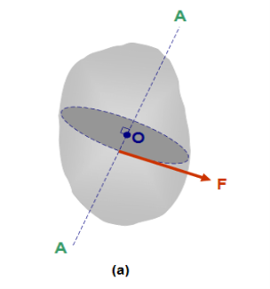
The moment of force F about point “O” in Figure 26(a) is a measure of the tendency of the force to rotate the body about line A-A. Line A-A is perpendicular to the plane containing force F and point “O”. Figure 26 (b) shows the plane containing F and “O”. Point “O” is called the moment centre, distance “d” is called the moment arm and line A-A is called the axis of the moment.
 |
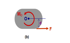 |
Figure 26
Properties of a Moment
- Moments not only have a magnitude, they also have a sense to them. The sense of a moment is clockwise or counter-clockwise depending on which way it will tend to make the object rotate. A clockwise rotation about the center of moments will be considered a positive moment; while a counter-clockwise rotation about the center of moments will be considered negative. The most common way to express a moment is
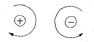
Figure 27
- The sense of a Moment is defined by the direction it is acting on the Axis and can be found using Right Hand Rule.
COUPLE
A couple consists of two equal, non collinear, parallel forces of opposite sense. A couple is a pair of forces, equal in magnitude, oppositely directed, and displaced by perpendicular distance, d.
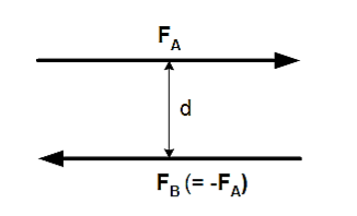
Figure 28
Moment of a couple = magnitude of force × perpendicular distance between the forces
Since the forces are equal and oppositely directed, the resultant force is zero. But the displacement of the force couple (d) does create a couple moment. The moment, M, about some arbitrary point O can be calculated.
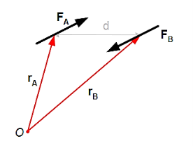
Figure 29

If point O is placed on the line of action of one of the forces, say FB, then that force causes no rotation (or tendency toward rotation) and the calculation of the moment is simplified.
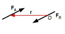
Figure 30
This is a significant result: The couple moment, M, depends only on the position vector r between forces FA and FB. The couple moment does not have to be determined relative to the location of a point or an axis.
Characteristics
- As the two forces forming couple are equal and opposite the couple doesn't produce translational motion.
- When it acts on a body net resultant force acting on a body is zero.
- It produces pure rotational motion in the body this is because the algebraic sum of the moments of the two forces about any point in their plane is not zero.
- The moment of a couple about any point in its plane is constant, both in magnitude and direction.
Application of a Couple
Couple is required to turn
- a car the driver applies a couple to the steering wheel
- To wind the spring of an alarm clock, it is applied by the fingers
- To open or dose a water tap
- To turn a key of a lock.
- To open or dose a cap of a bottle.
What is the difference between Moment and Couple?
• Moment of force is the measure of turning effect of a force about a point. A couple consists of two equal and opposite forces acting with two different but parallel lines of action. Each force has its own moment.
• Moment of a force is dependent on the distance from the pivot and the magnitude of the force while the moment of a couple is the net effect of the two moments of the forces. Moment of a couple is independent of the location of the point considered. It is constant throughout the plane.
Example: Two couples act on the beam with the geometry shown in figure. Find the magnitude of F so that the resultant couple moment is 1.5 kNm clockwise.
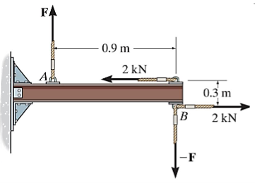
Figure 31
Solution:
The net moment is equal to :
M = –F (0.9) + (2) (0.3) = –0.9 F + 0.6
–1.5 kNm = –0.9 F + 0.6
Solving for the unknown force F, we get
F = 2.33 kN
We know that the time rate of change of angular momentum of a rigid body about a fixed point is equal to the resultant external torque acting on the body about that fixed point. That is
 =
=  ……….(1)
This equation is valid in a system of axes oxyz which has a fixed orientation in space. The origin O of the coordinate system must be at a fixed point of the body. In order to study the rotation of a rigid body, we need to go to a system of axes fixed in the body with its origin coincident with O. Thus it is necessary to express eq. (1) in terms of the rotating axes.
We know that the time rate of change of any vector  in fixed frame is related to time rate of change of this vector in rotating frame by the relation
( )s = (
 )R +
)R + 
 …………(2)
Applying this result to eq. (1) we obtain
 =
=  )R +
)R + 
 …………(3)
The coordinate axes attached to the body rotate with the body. We consider the instant when the fixed set of axes coincide with the rotating set of axes. At this instant
 )R=
)R=  )R +
)R + 
 ) R …………(4)
This is the equation of motion of a rigid body in the rotating system. We shall omit subscript R in future discussion.
It has been shown that the expression for the angular momentum assumes a simple form if the coordinate axes attached to body are principle axes. The reason is that the products of intertia vanish in such axes. For principle axes, the expression for  is
is
 = Ixxωx
 +Iyyωy
  + Izz ωz
  …………(5)
Where Ixx, Iyy and Izz are the principle moments of intertia of the body and are independent of time.
Differentiate eq. (5) with respect to time. This gives
 = Ixx
= Ixx 
 +Iyy
+Iyy
 + Izz
+ Izz 
 …………(6)
Let us now evaluate the second term in eq. (4) i.e., the cross product of angular momentum  with
with  . This gives

 =
= 

 =
=  (
( ) +
) +  (
( ) +
) + 

 =
=  (
( ) +
) +  (
( ) +
) +  …………(7)
Substituting these values in eq. (4) we obtain
 = Ixx
= Ixx 
 +Iyy
+Iyy
 + Izz
+ Izz 
 +
+ (
( ) +
) +  (
( ) +
) + 
 = [Ixx
  + (
+ ( )
) ]
]  +[Iyy
+[Iyy +
+ (
( )
)
 + [Izz
  +
+
 …………(8)
In rectangular components, the above equation may be written as
 = Ixx
= Ixx  +
+ (
( )
)
 = Iyy
= Iyy +
+ (
( )
)
 = Izz
= Izz  +
+
The three equations given above for  ,
, and
and  are known as Euler’s equations for the motion of a rigid body. They relate the torque about each one of the principle axes to the angular velocity of the principle axes. Note that Euler’s equations are merely by the components of
  =
= relative to the rotating principle axes.