UNIT 3
Electrical Machines
The fundamental principle of induction machine is the creation of rotating and sinusoidally distributed magnetic field in the air gap. Three phase balanced power supply is fed to the three-phase stator winding creates a synchronously rotating magnetic field. Due to relative speed between rotating flux and stationary conductors, an emf is induced. The frequency to induced emf is same as supply frequency.
As shown in below fig.a , the stator field is assumed to clockwise. The relative motion of rotor w.r.t stator is anticlockwise. From Right-hand rule, the direction of induced emf in rotor is outwards. By the effect of combined field as shown in fig b the rotor experiences a force tending to rotate it in clockwise direction. Hence rotor rotates in the same direction as the stator field.
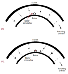
The speed of this rotating field is called synchronous speed. If the rotor is initially stationary, its conductors will be subjected to a changing magnetic field, inducing current in the short-circuited rotor at the same frequency. The interaction of air gap flux and rotor mmf produces torque. At synchronous speed rotor cannot have any torque.
Construction:
There are two main parts of induction motor:
a) Stator
b) Rotor
a) Stator:
It is stationary part of induction motor. It has number of stampings. It is wound with three phase winding which is fed from 3-phase supply. The number of poles here are defined, they are selected according to the speed required. If required speed is greater than we need a smaller number of poles. The stator produces an alternating flux when fed with supply which revolves with synchronous speed(Ns = 120f / P). The synchronous speed is inversely proportional to number of poles.
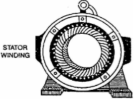
Fig: Stator
b) Rotor: It is rotating part of induction motor.
There are two types of rotor
I)Squirrel cage rotor:
The rotor consists of a cylindrical core with parallel slots for carrying the rotor conductor. Each slot has one copper or aluminium bar. Each end of all bars is joined with metal ring. The entire construction resembles a squirrel cage. The rotor is not connected electrically to the supply it has induced current from stator. Almost 90% of induction motors are squirrel cage type. But is has a disadvantage of low starting torque, because the rotor bars are permanently short-circuited.
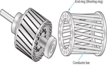
Fig Squirrel cage rotor
Ii) Phase-wound rotor: It has laminated cylindrical core and the windings are uniformly distributed in the slots which are usually star connected. The other three winding terminals are brought out and connected to three insulated slip rings mounted on shaft with brushes resting on them. The three brushes are connected to a 3-phase star-connected rheostat as shown in Figure below.
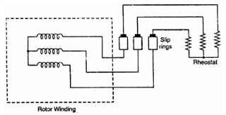
Fig: 3-phase star connected
At starting, the external resistances are included in the rotor circuit to give a large starting torque. These resistances are gradually reduced to zero as the motor runs up to speed. The external resistances are used during starting period only. When the motor attains normal speed, the three brushes are short-circuited so that the wound rotor runs like a squirrel cage rotor.
Principle of working
The fundamental principle of induction machine is the creation of rotating and sinusoidally distributed magnetic field in the air gap. Three phase balanced power supply is fed to the three-phase stator winding creates a synchronously rotating magnetic field. Due to relative speed between rotating flux and stationary conductors, an emf is induced. The frequency to induced emf is same as supply frequency.
As shown in below fig.a , the stator field is assumed to clockwise. The relative motion of rotor w.r.t stator is anticlockwise. From Right-hand rule, the direction of induced emf in rotor is outwards. By the effect of combined field as shown in fig b the rotor experiences a force tending to rotate it in clockwise direction. Hence rotor rotates in the same direction as the stator field.
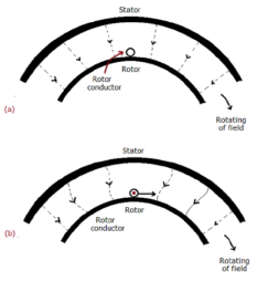
The speed of this rotating field is called synchronous speed. If the rotor is initially stationary, its conductors will be subjected to a changing magnetic field, inducing current in the short-circuited rotor at the same frequency. The interaction of air gap flux and rotor mmf produces torque. At synchronous speed rotor cannot have any torque.
Starting
The 1-phase motor is not self-starting. They require mechanical means to start. The basic methods are
Speed Control: The speed can be controlled by the following methods.
i) Changing stator Pole: This can be done by Multiple stator windings. In stator two windings are provided which are isolated and have different number of poles. By switching we can control the supply to one winding and hence control the speed.
Ii) Supply voltage control: The torque produced is proportional to  . The value of
  is very small and R2 is also constant so T α
 . But E2 α V therefore, T α sV2. This equation shows that if supply voltage is decreased the torque also decreases.
Iii) Adding rheostat in the stator: As we already know T α  . The value of
  is very small and E2 is also constant so T α
  . Now if we increase rotor resistance, R2 torque decreases but to supply the same load torque must remain constant. So, we increase slip, which will further result in the decrease in rotor speed. Thus, by adding additional resistance in the rotor circuit, we can decrease the speed of the three-phase induction motor.
Iv) v/f control: There is no direct relation in the speed and torque. At, full load the motor runs at a speed N. When mechanical load increases motor speed decreases till the motor torque again becomes equal to the load torque.
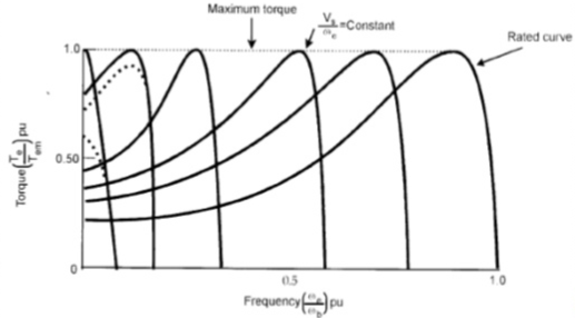
As long as two torques are equal the motor runs at constant speed. When the supply frequency increases the speed increases and reduces the maximum torque of motor. So,
i) F increases, N increases, Tmax decreases.
Ii) V increases, Tmax increases.
There are two main parts of induction motor:
c) Stator
d) Rotor
c) Stator:
It is stationary part of induction motor. It has number of stampings. It is wound with three phase winding which is fed from 3-phase supply. The number of poles here are defined, they are selected according to the speed required. If required speed is greater than we need a smaller number of poles. The stator produces an alternating flux when fed with 3-phase supply which revolves with synchronous speed(Ns = 120f / P). The synchronous speed is inversely proportional to number of poles.
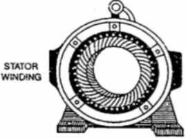
Fig: Stator
d) Rotor: It is rotating part of induction motor. There are two types of rotor
I)Squirrel cage rotor:
The rotor consists of a cylindrical core with parallel slots for carrying the rotor conductor. Each slot has one copper or aluminium bar. Each end of all bars is joined with metal ring. The entire construction resembles a squirrel cage. The rotor is not connected electrically to the supply it has induced current from stator. Almost 90% of induction motors are squirrel cage type. But is has a disadvantage of low starting torque, because the rotor bars are permanently short-circuited.
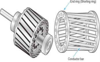
Fig Squirrel cage rotor
Ii) Phase-wound rotor: It has laminated cylindrical core and the windings are uniformly distributed in the slots which are usually star connected. The other three winding terminals are brought out and connected to three insulated slip rings mounted on shaft with brushes resting on them. The three brushes are connected to a 3-phase star-connected rheostat as shown in Figure below.
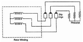
Fig: 3-phase star connected
At starting, the external resistances are included in the rotor circuit to give a large starting torque. These resistances are gradually reduced to zero as the motor runs up to speed. The external resistances are used during starting period only. When the motor attains normal speed, the three brushes are short-circuited so that the wound rotor runs like a squirrel cage rotor.
Slip:
The rotor can never have same speed as that of stator. If it occurs then there will not be relative speed between the two, hence no rotor emf, no rotor current and so no torque to maintain rotation. Due to this reason speed of rotor is always less than the stator field. The difference between the synchronous speed Ns and the actual speed N of the rotor is called as slip.
% slip s=
Therefore, rotor speed N=Ns(1-s).
Frequency of rotor current:
When rotor is stationary its frequency is same as the supply frequency. But when rotor revolves its frequency depends upon the slip-speed. Let frequency of rotor current be f’
Ns-N=
But Ns=

Rotor current have same frequency

=
MMF produced by rotor current:
a) For standstill condition:
Let E2=emf induced per phase of rotor at standstill
R2=resistance per phase of rotor.
X2=reactance per phase of rotor at standstill=2 f1L2
f1L2
Z2=rotor impedance per phase
I2=rotor current per phase
Z2=R2+jX2
 =
=
Power Factor cosφ2= =
=
b) Rotor current at slip s:
Induced emf per phase in rotor winding at slip s is E2s=sE2
Rotor winding reactance per phase at slip s will be X2s=2 f2L=sX2
Rotor winding impedance per phase at slip s is Z2s=R2+jX2s=R2+jsX2
Rotor current at slip s, I2s=
Power factor at slip s is cosφ2s=
Que) The stator of a 3-phase induction motor has 5 slots per pole per phase. If supply frequency is 50Hz. Calculate a) number of stator poles produced and total number of slots in stator. b) Speed of rotating stator flux.?
Sol: a) P=2n=2*5=10 poles
Total number of slots= 5 slots/pole/phase * 10 poles * 3 phases=150
e) Ns= =120x50/10=600rpm
Que) A 3-phase induction motor is wound for 5 poles and is supplied from 50 Hz. Calculate a) synchronous speed b) rotor speed when slip is 4% c) rotor frequency when rotor runs at 500 rpm?
Sol: a) Ns= =120x50/5=1200 rpm
b)rotor speed N=Ns(1-s)=1200(1-0.04)=1152 rpm
c)when rotor speed is 500 rpm, slip s=(Ns-N)/Ns=(1200-500)/1200=0.58
Rotor current frequency f’=sf=0.58x50=29.17 Hz
Que) A 3-phase, 50 Hz,3-pole induction motor has a slip of 4%.Calculate a)speed of rotor. B) frequency of rotor emf. If the rotor as a resistance of 2ohm, and standstill reactance of 4ohm,calculate the power factor c)at standstill and d)at a speed of 1200rpm?
Sol: Ns= =120x50/3=2000 rpm
a) Speed of rotor N=Ns(1-s)=2000(1-0.04)=1920 rpm
b) Frequency or rotor = f’=sf=0.04x50=2Hz
R2=2ohm, X2=4ohm
Z2=R2+jX2=2+j4=4.47 63.43o ohm
c)Power factor cosφ2=0.44(lag)
Slip at speed 1200rpm s= 2000-1200/2000=0.4
Rotor impedance at slip s=0.4 is
Z2s=R2+jsX2=2+jx0.4x4=2.56 oohm
oohm
Power factor at 1200rpm is cos φ2s=cos38.66o=0.78(lag)
Q) A 3-phase induction motor star connected rotor has an induced emf of 70volts between slip rings at standstill on open circuit. The rotor has a resistance and reactance per phase of 1ohm and 5ohm respectively. Calculate current/phase and power factor when slip rings are short circuited?
Sol: Standstill emf/rotor phase=70/
Rotor impedance/phase= ohm
ohm
Rotor current/phase=40.4/5.09=7.92A
Power factor cosφ=0.99
Que) A 3-phase induction motor star connected rotor has an induced emf of 70volts between slip rings at standstill on open circuit. The rotor has a resistance and reactance per phase of 1ohm and 5ohm respectively. Calculate current/phase and power factor when slip rings are connected to star connected rheostat of 2ohm?
Sol: Rotor resistance/phase=2+1=3 ohm
Rotor impedance/phase= =5.83 ohm
Rotor current/phase= (70/ )/5.83=6.93A
Cosφ=3/5.83=0.514
Que) A 6-pole, 3-phase induction motor operates from a supply whose frequency is 50Hz. Calculate I) speed at which the magnetic field of stator is rotating. Ii)speed of rotor when slip is 4%. Iii)frequency of rotor current when slip is 3%?
Sol: I) Stator revolves at synchronous speed. So, Ns=120f/P=120 x 50/6=1000rpm
Ii)rotor speed N=(1-s) Ns= (1-0.04) x 1000=960rpm
Iii)frequency of rotor current f’=sf=0.03 x 50=90rpm
Construction – A simple generator is shown below, the essential parts of which are
1) Yoke – It is the outer frame of machine which carries the magnetic flux produced by poles and also provides mechanical support to the poles. The yoke is generally made of cast steel or rolled steel.
2) Pole shoes – They are made up of thin lamination of annealed steel, which are piled up under hydraulic pressure. They spread out the flux in the air gap. They reduce the reluctance as they have large cross-sectional area.
3) Held coils –They are the copper wire which are wounded around the core, the flux is produced when the current passes through these coils.
4) Armature core – It provides the low reluctance path to the flux through the armature. It carries the conductor coils and makes them to rotate, which in turn tells the magnetic flux produced. It is cylindrical in shape and made of circular steel sheets.
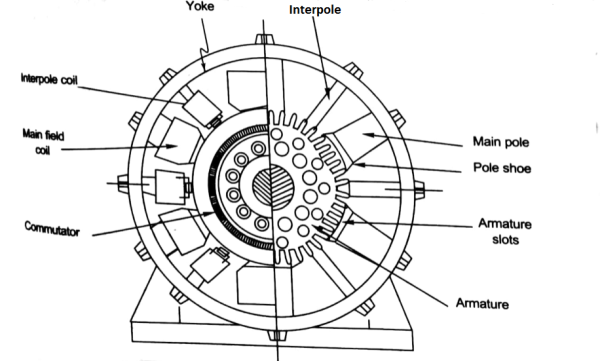
5) Armature Windings – These windings are arranged in armature slots; the slots are lined with tough insulating material. The useful EMF is encouraged in these findings and is received across brushes.
6) Commutator - It collects the current from armature and supplies to the load. It is cylindrical in shape. It periodically reverses the current direction between the rotor and external circuit. It is composed of multiple metal segments insulated from each other by thin layer of Mica. The number of segments is equal to number of armature coil.
7) Brushes and bearings - The brushes are usually made of carbon or graphite. The main function of brushes is to collect current from commutator. They are housed in brush holders and mounted on a spindle. The number of brushes per spindle depends upon the magnitude of the current to be collected from commutator.
Working
The basic circuit model for a dc machine is shown below:
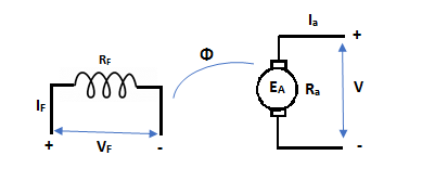
The machine operates in generating mode when the armature current is in the direction of induced emf Ea.
V = Ea – Ia Ra Ea> V
Pmech = Ea Ra = Pelect
The output power,
P0 = VIa
EaIa – VIa = Ia2 Ra
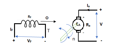
In this mode, the torque of electromagnetic origin is in opposite direction of rotation of armature.
[Pmech]gross = Shaft power = [Pmech]net + Rotational loss.
The average coil emf

Wm = armature speed rad/s.
As parallel path emf is equal to armature emf,


Np = turns / parallel path = 
Z = Total armature conductors
A = Number of parallel paths.


n = armature speed rpm
Torque equation
Average conductor force
Fav = Bav l Ic
Bav = avg. Flux density over pole.
l = active conductor length.
Force, F = ZFav = BavlIcZ
T = f.r
T = Bav l IC Zr
r = mean of r gap radius.
Flux/pole = Bav
= Bav Pl
Pl


The torque is uniform for given flux/pole and armature current.
Q. 1 A 4 pole dc generator runs at 650 rpm and generates emf of 220V. The armature is wave wound and has 790 conductors. If total flux/pole is 0.0145 Wb in each pole, find leakage coefficient.
Soln. Leakage coefficient =
Working flux is given as


A = 2 for simple wave winding.

Leakage coefficient =
Q. 2A 4 pole lap wound dc shunt generator has a useful flux per pole of 0.05 Wb. The armature winding consists of 200 turns each of 0.06 u ohm resistance. Calculate the terminal voltage when running at 900 rpm with armature current of 50 A.
Soln. Terminal voltage V =Ea – Ia Ra
Ia Ra = 50×Ra.

Z = 200×2=400 (each turn has two sides).
N = 900 rpm  = 0.05 Wb P = A = 4

Total resistance of 200 turns = 200 × 0.004 = 0.8 ohm
As there are 4 parallel paths, so resistance of each path = 0.8/4 = 0.2 ohm
There are 4 resistances in parallel of each of 0.2 ohm
Ra = 0.2/4 = 0.05 ohm
Ia Ra = 50×0.05 = 25 V
V = Ea – Ia Ra = 300 – 25 = 275 V
Q. 3 A 220 V 4 pole wave wound dc series motor has 780 conductors on its armature. It has armature and series field resistance of 0.75 ohm. The motor takes a current of 30A. Find the speed and gross torque developed if flux/pole is 20 mWb?
Soln. Back emf, 
Eb = V – IaRa = 220 – (30×0.75) = 197.5 V
197.5 = 20 × 10-3 ×780×N×0.75
N = 16.88 ≈ 17


Ta = 158.97 Nm.
S
For DC Series Motor
Speed and Torque characteristics: As Ta α φ Ia and φ α Ia , but N αEb/ Ia .So it can be easily concluded that speed and torque are inversely proportional. Hence when speed is high torque is low and vice versa. The curve is shown below.
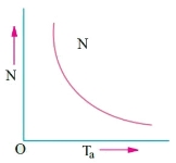
Fig: Speed verses Torque characteristics
For DC Shunt Motor
Speed and Torque Characteristics: From above to characteristics, curve for this shown below.
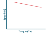
Fig: Speed verses Torque characteristics
Que) A 250V shunt motor on no load runs at 900rpm and takes 4amperes, armature and shunt field resistances are 0.2 and 250 ohms respectively. Calculate the speed when loaded taking current of 50A. The armature reactions weaken the field by 3%?
Sol: Ish=250/250=1A
Ia1=4-1=3A
Ia2=50-1=49A
Eb1=250-3*0.4=248.8V
Eb2=250-49*0.2=240.2A


N2=898rpm
Que) The speed of a 37.3kW series motor working on 500V supply is 600 rpm at full load and 90% efficiency. If the load torque is made 250 N-m and a 5ohm resistance is connected in series with the machine, calculate the speed at which the machine will run. Assume armature and field resistance of 0.5ohm?
Sol: Load torque in first case T1=37300/2 (600/60)=593.65 N-m
Input current Ia1=37300/0.9*500=82.9A
T2=250 N-m. So, finding Ia2
For series motor T α φ Ia α Ia2
T1 α  and T2 α

 =82.9*
 =53.79A
Eb1=500-(82.9*0.5)=458.5V
Eb2=500-53.79(5+0.5)=204.11V


The speed control of DC motor is given by
N= rpm
rpm
The speed can be controlled by varying
I)Φ=flux/pole
Ii)Ra=Armature resistance
Iii)V=Applied voltage
For DC Series Motor: In DC Series motor speed control can be done in two ways:
I)Flux Control: In this there are four ways to control speed
a) Field Divertors
b) Armature Divertors
c) Trapped Field control field
d)Paralleling field coils
Ii) Variable resistance in series with motor
Firstly, discussing the Flux Control method to control speed in DC Series motor.
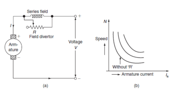
a) Field Divertors: In this one variable resistance in parallel to the field winding is connected. It is called as field divertor. We can control the current through the field divertor by adjusting its resistance. As we can control the current , the flux can also be decreased and hence the speed will increase. Below shows the figure.
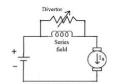
Fig: Field Divertor
b)Armature Divertor: In this the variation in speed can be controlled by varying the divertor resistance. As we know TaαφIa and Nα . Hence if flux increases (as Ia can be reduced due to armature divertor) speed will decrease. The figure is shown below .
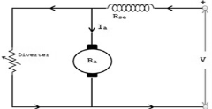
Fig: Armature Divertor
c)Trapped Field control field: In this the series field turns can be changed according to our wish. The speed can be increased by removing off some of the series turns. The figure is shown below.
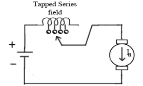
Fig: Trapped Field control field
d)Paralleling field coils: In this speed control can be done by regrouping the field coils.
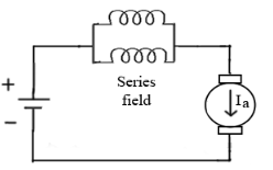
Fig: Paralleling of field coils
Ii) Variable resistance in series with motor: The voltage across armature can be reduced increasing the resistance in series with it. As the voltage reduces the speed also reduces. The below fig a show the variable resistance across armature and fig b shows the variation of speed with respect to armature current.
For DC Shunt Motor: There are three basic methods to control the speed of DC Shunt motor listed below
I)Flux control method
Ii)Armature or Rheostatic control
Iii)Voltage control
I)Flux control method: As we already know that flux and speed for shunt motors are inversely proportional to each other. As the name suggests flux control which means we can control the flux and maintain required speed. The flux can be controlled by changing Ishwith help of shunt field rheostat. The figure is shown below.
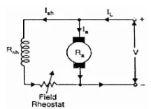
Fig: Flux control method
Ii)Armature or Rheostatic control: This is the most common method employed. In this the controlling resistance is connected directly in series with the supply of the motor. As resistance Ra is increased potential drop across armature decreases, and hence the speed too decreases. The figure is shown below.
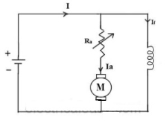
Fig: Armature control
One more to control speed here is shunting the armature and a rheostat in series with the armature is involved in this method of speed control. The voltage applied to the armature varies by varying series rheostat R1. The exciting current can be varied by varying the armature shunting resistance R2. This method of speed control is not economical due to considerable power losses in speed controlling resistances.
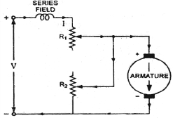
Fig: shunted armature speed control
Iii)Voltage control method: There are two ways in voltage control method
a) Multiple voltage control: In this method the shunt field of motor is connected permanently to a fixed exciting voltage, but armature is supplied with different voltages. The armature speed is approximately proportional to these different voltages. This method is not used now.
b) Ward-Leonard System: The figure below shows the ward-Leonard system. In this method speed of motor M1is controlled which is powered by generator G. The shunt field of motor is connected across DC supply. The motor M2derives the generator. When the output voltage of the generator is fed to the motor M1 then the motor starts to rotate. When the output voltage of the generator varies then the speed of the motor also varies. By controlling the output voltage of generator speed of motor can be controlled. To attain this a field regulator is connected across the generator. The direction of rotation of motor can be reversed by excitation current of generator, this will happen by reversing the switch R.S. The motor-generator should run in same direction.
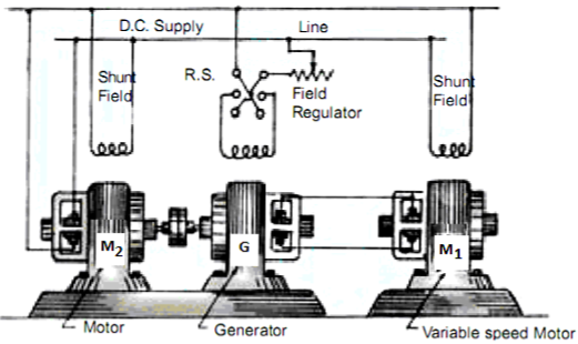
Fig: Ward Leonard System
Que) A dc series motor drives a load torque of which varies as the square of the speed. The motor takes a current of 15A when speed is 500 rpm. Calculate the speed and the current when the motor field winding is shunted by a diverter of same resistance as that of the field winding.
Sol: As we already know TaαφIa and Nα
Ta1 α 
Ta2 α 

Ta1 α φ1Ia1
Ta2 α φ2Ia2
As field current is half the armature current so 
 ………(1)

Neglecting armature and series winding drop.
 ………(2)
From 1 and 2


 =
= 152=25.2A
From 2 we get N2=500*2*15/25.2=595.2 rpm
Que) A 200V dc shunt motor running at 900rpm takes an armature current of 15.5A. It is required to reduce the speed to 600 rpm. What must be the value of resistance to be inserted in the armature circuit if the original resistance is0.4Ω?
Sol:N1=900rpm
Eb1=200-15.5*0.4=193.8 V
N2=600rpm
Eb2=200-15.5*Rt
Rt= total armature circuit resistance
Assuming armature current constant. Φ1= Φ2

Rt=4.57 Ω
Additional resistance required=Rt-Ra=4.57-0.4=4.17 Ω
The synchronous generator consists of rotor and stator. The rotor has field poles and stator has armature conductors. When the field poles rotate an induced alternating voltage is produced. The synchronous speed is given by
Ns=
P: Number of Poles
f: frequency
Basic mechanism in operation of these generators is EMI. An emf is induced due to the movement of conductors and flux. When the same poles of rotor and stator are near each other they repel and tend to rotate, and the rotor rotates (in anticlockwise direction). But half a period later stator poles having rotated around interchange their positions. Under this condition the poles attract each other and rotor rotates (in clockwise direction). Hence, due to continuous and rapid rotation of stator poles, the rotor is subjected to a torque which is rapidly reversing. When stator and rotor poles are attracting each other and rotor is not stationary but in CW direction with such a speed that it turns through one pole pitch by time the stator poles are interchanged. It means that if rotor poles change their position along with the stator poles, they also continuously experience a unidirectional torque.