UNIT 1
Introduction To Computers
A computer system is basically a machine that simplifies complicated tasks. It should maximize performance and reduce costs as well as power consumption. The different components in the Computer System Architecture are Input Unit, Output Unit, Storage Unit, Arithmetic Logic Unit, Control Unit etc.
A diagram that shows the flow of data between these units is as follows −
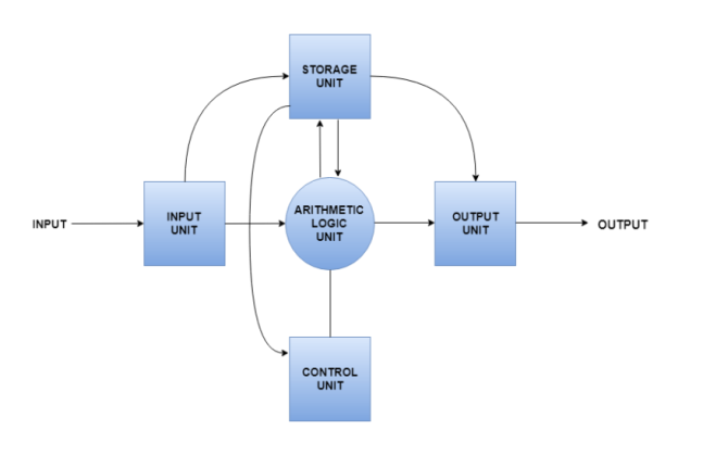
The input data travels from input unit to ALU. Similarly, the computed data travels from ALU to output unit. The data constantly moves from storage unit to ALU and back again. This is because stored data is computed on before being stored again. The control unit controls all the other units as well as their data.
Details about all the computer units are −
- Input Unit
The input unit provides data to the computer system from the outside. So, basically it links the external environment with the computer. It takes data from the input devices, converts it into machine language and then loads it into the computer system. Keyboard, mouse etc. are the most commonly used input devices.
- Output Unit
The output unit provides the results of computer process to the users i.e. it links the computer with the external environment. Most of the output data is the form of audio or video. The different output devices are monitors, printers, speakers, headphones etc.
- Storage Unit
Storage unit contains many computer components that are used to store data. It is traditionally divided into primary storage and secondary storage. Primary storage is also known as the main memory and is the memory directly accessible by the CPU. Secondary or external storage is not directly accessible by the CPU. The data from secondary storage needs to be brought into the primary storage before the CPU can use it. Secondary storage contains a large amount of data permanently.
- Arithmetic Logic Unit
All the calculations related to the computer system are performed by the arithmetic logic unit. It can perform operations like addition, subtraction, multiplication, division etc. The control unit transfers data from storage unit to arithmetic logic unit when calculations need to be performed. The arithmetic logic unit and the control unit together form the central processing unit.
- Control Unit
This unit controls all the other units of the computer system and so is known as its central nervous system. It transfers data throughout the computer as required including from storage unit to central processing unit and vice versa. The control unit also dictates how the memory, input output devices, arithmetic logic unit etc. should behave.
CPU (Central Processing Unit)
Central Processing Unit (CPU) consists of the following features −
- CPU is considered as the brain of the computer.
- CPU performs all types of data processing operations.
- It stores data, intermediate results, and instructions (program).
- It controls the operation of all parts of the computer.
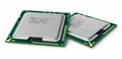
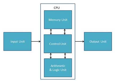
CPU itself has following three components.
- Memory or Storage Unit
- Control Unit
- ALU(Arithmetic Logic Unit)
Memory or Storage Unit
This unit can store instructions, data, and intermediate results. This unit supplies information to other units of the computer when needed. It is also known as internal storage unit or the main memory or the primary storage or Random-Access Memory (RAM).
Its size affects speed, power, and capability. Primary memory and secondary memory are two types of memories in the computer. Functions of the memory unit are −
- It stores all the data and the instructions required for processing.
- It stores intermediate results of processing.
- It stores the final results of processing before these results are released to an output device.
- All inputs and outputs are transmitted through the main memory.
Control Unit
This unit controls the operations of all parts of the computer but does not carry out any actual data processing operations.
Functions of this unit are −
- It is responsible for controlling the transfer of data and instructions among other units of a computer.
- It manages and coordinates all the units of the computer.
- It obtains the instructions from the memory, interprets them, and directs the operation of the computer.
- It communicates with Input/output devices for transfer of data or results from storage.
- It does not process or store data.
ALU (Arithmetic Logic Unit)
This unit consists of two subsections namely,
- Arithmetic Section
- Logic Section
Arithmetic Section
Function of arithmetic section is to perform arithmetic operations like addition, subtraction, multiplication, and division. All complex operations are done by making repetitive use of the above operations.
Logic Section
Function of logic section is to perform logic operations such as comparing, selecting, matching, and merging of data.
Memory
A memory is just like a human brain. It is used to store data and instructions. Computer memory is the storage space in the computer, where data is to be processed and instructions required for processing are stored. The memory is divided into large number of small parts called cells. Each location or cell has a unique address, which varies from zero to memory size minus one. For example, if the computer has 64k words, then this memory unit has 64 * 1024 = 65536 memory locations. The address of these locations varies from 0 to 65535.
Memory is primarily of three types −
- Cache Memory
- Primary Memory/Main Memory
- Secondary Memory
Cache Memory
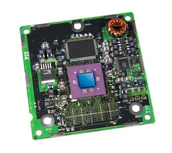
Cache memory is a very high-speed semiconductor memory which can speed up the CPU. It acts as a buffer between the CPU and the main memory. It is used to hold those parts of data and program which are most frequently used by the CPU. The parts of data and programs are transferred from the disk to cache memory by the operating system, from where the CPU can access them.
Advantages
The advantages of cache memory are as follows −
- Cache memory is faster than main memory.
- It consumes less access time as compared to main memory.
- It stores the program that can be executed within a short period of time.
- It stores data for temporary use.
Disadvantages
The disadvantages of cache memory are as follows −
- Cache memory has limited capacity.
- It is very expensive.
Primary Memory (Main Memory)
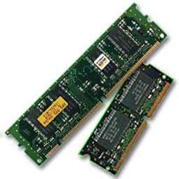
Primary memory holds only those data and instructions on which the computer is currently working. It has a limited capacity and data is lost when power is switched off. It is generally made up of semiconductor device. These memories are not as fast as registers. The data and instruction required to be processed resides in the main memory. It is divided into two subcategories RAM and ROM.
Characteristics of Main Memory
- These are semiconductor memories.
- It is known as the main memory.
- Usually volatile memory.
- Data is lost in case power is switched off.
- It is the working memory of the computer.
- Faster than secondary memories.
- A computer cannot run without the primary memory.
Secondary Memory
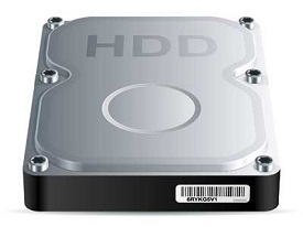
This type of memory is also known as external memory or non-volatile. It is slower than the main memory. These are used for storing data/information permanently. CPU directly does not access these memories, instead they are accessed via input-output routines. The contents of secondary memories are first transferred to the main memory, and then the CPU can access it. For example, disk, CD-ROM, DVD, etc.
Characteristics of Secondary Memory
- These are magnetic and optical memories.
- It is known as the backup memory.
- It is a non-volatile memory.
- Data is permanently stored even if power is switched off.
- It is used for storage of data in a computer.
- Computer may run without the secondary memory.
- Slower than primary memories.
Communication between various devices of computer using bus
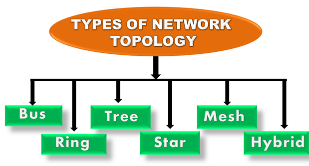
Topology defines the structure of the network of how all the components are interconnected to each other. There are two types of topology: physical and logical topology.
Physical topology is the geometric representation of all the nodes in a network.
Bus Topology
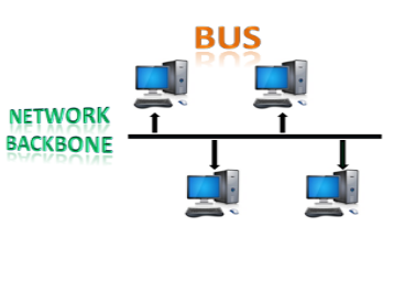
- The bus topology is designed in such a way that all the stations are connected through a single cable known as a backbone cable.
- Each node is either connected to the backbone cable by drop cable or directly connected to the backbone cable.
- When a node wants to send a message over the network, it puts a message over the network. All the stations available in the network will receive the message whether it has been addressed or not.
- The bus topology is mainly used in 802.3 (ethernet) and 802.4 standard networks.
- The configuration of a bus topology is quite simpler as compared to other topologies.
- The backbone cable is considered as a "single lane" through which the message is broadcast to all the stations.
- The most common access method of the bus topologies is CSMA (Carrier Sense Multiple Access).
CSMA: It is a media access control used to control the data flow so that data integrity is maintained, i.e., the packets do not get lost. There are two alternative ways of handling the problems that occur when two nodes send the messages simultaneously.
- CSMA CD: CSMA CD (Collision detection) is an access method used to detect the collision. Once the collision is detected, the sender will stop transmitting the data. Therefore, it works on "recovery after the collision".
- CSMA CA: CSMA CA (Collision Avoidance) is an access method used to avoid the collision by checking whether the transmission media is busy or not. If busy, then the sender waits until the media becomes idle. This technique effectively reduces the possibility of the collision. It does not work on "recovery after the collision".
Advantages of Bus topology:
- Low-cost cable: In bus topology, nodes are directly connected to the cable without passing through a hub. Therefore, the initial cost of installation is low.
- Moderate data speeds: Coaxial or twisted pair cables are mainly used in bus-based networks that support up to 10 Mbps.
- Familiar technology: Bus topology is a familiar technology as the installation and troubleshooting techniques are well known, and hardware components are easily available.
- Limited failure: A failure in one node will not have any effect on other nodes.
Disadvantages of Bus topology:
- Extensive cabling: A bus topology is quite simpler, but still it requires a lot of cabling.
- Difficult troubleshooting: It requires specialized test equipment to determine the cable faults. If any fault occurs in the cable, then it would disrupt the communication for all the nodes.
- Signal interference: If two nodes send the messages simultaneously, then the signals of both the nodes collide with each other.
- Reconfiguration difficult: Adding new devices to the network would slow down the network.
- Attenuation: Attenuation is a loss of signal leads to communication issues. Repeaters are used to regenerate the signal.
Ring Topology
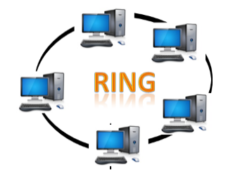
- Ring topology is like a bus topology, but with connected ends.
- The node that receives the message from the previous computer will retransmit to the next node.
- The data flows in one direction, i.e., it is unidirectional.
- The data flows in a single loop continuously known as an endless loop.
- It has no terminated ends, i.e., each node is connected to other node and having no termination point.
- The data in a ring topology flow in a clockwise direction.
- The most common access method of the ring topology is token passing.
- Token passing: It is a network access method in which token is passed from one node to another node.
- Token: It is a frame that circulates around the network.
Working of Token passing
- A token moves around the network, and it is passed from computer to computer until it reaches the destination.
- The sender modifies the token by putting the address along with the data.
- The data is passed from one device to another device until the destination address matches. Once the token received by the destination device, then it sends the acknowledgment to the sender.
- In a ring topology, a token is used as a carrier.
Advantages of Ring topology:
- Network Management: Faulty devices can be removed from the network without bringing the network down.
- Product availability: Many hardware and software tools for network operation and monitoring are available.
- Cost: Twisted pair cabling is inexpensive and easily available. Therefore, the installation cost is very low.
- Reliable: It is a more reliable network because the communication system is not dependent on the single host computer.
Disadvantages of Ring topology:
- Difficult troubleshooting: It requires specialized test equipment to determine the cable faults. If any fault occurs in the cable, then it would disrupt the communication for all the nodes.
- Failure: The breakdown in one station leads to the failure of the overall network.
- Reconfiguration difficult: Adding new devices to the network would slow down the network.
- Delay: Communication delay is directly proportional to the number of nodes. Adding new devices increases the communication delay.
Star Topology

- Star topology is an arrangement of the network in which every node is connected to the central hub, switch or a central computer.
- The central computer is known as a server, and the peripheral devices attached to the server are known as clients.
- Coaxial cable or RJ-45 cables are used to connect the computers.
- Hubs or Switches are mainly used as connection devices in a physical star topology.
- Star topology is the most popular topology in network implementation.
Advantages of Star topology
- Efficient troubleshooting: Troubleshooting is quite efficient in a star topology as compared to bus topology. In a bus topology, the manager has to inspect the kilometres of cable. In a star topology, all the stations are connected to the centralized network. Therefore, the network administrator has to go to the single station to troubleshoot the problem.
- Network control: Complex network control features can be easily implemented in the star topology. Any changes made in the star topology are automatically accommodated.
- Limited failure: As each station is connected to the central hub with its own cable, therefore failure in one cable will not affect the entire network.
- Familiar technology: Star topology is a familiar technology as its tools are cost-effective.
- Easily expandable: It is easily expandable as new stations can be added to the open ports on the hub.
- Cost effective: Star topology networks are cost-effective as it uses inexpensive coaxial cable.
- High data speeds: It supports a bandwidth of approx. 100Mbps. Ethernet 100BaseT is one of the most popular Star topology networks.
Disadvantages of Star topology
- A Central point of failure: If the central hub or switch goes down, then all the connected nodes will not be able to communicate with each other.
- Cable: Sometimes cable routing becomes difficult when a significant amount of routing is required.
Tree topology
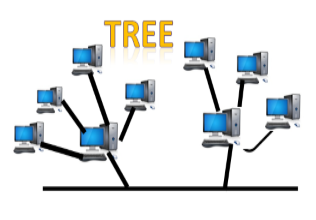
- Tree topology combines the characteristics of bus topology and star topology.
- A tree topology is a type of structure in which all the computers are connected with each other in hierarchical fashion.
- The top-most node in tree topology is known as a root node, and all other nodes are the descendants of the root node.
- There is only one path exists between two nodes for the data transmission. Thus, it forms a parent-child hierarchy.
Advantages of Tree topology
- Support for broadband transmission: Tree topology is mainly used to provide broadband transmission, i.e., signals are sent over long distances without being attenuated.
- Easily expandable: We can add the new device to the existing network. Therefore, we can say that tree topology is easily expandable.
- Easily manageable: In tree topology, the whole network is divided into segments known as star networks which can be easily managed and maintained.
- Error detection: Error detection and error correction are very easy in a tree topology.
- Limited failure: The breakdown in one station does not affect the entire network.
- Point-to-point wiring: It has point-to-point wiring for individual segments.
Disadvantages of Tree topology
- Difficult troubleshooting: If any fault occurs in the node, then it becomes difficult to troubleshoot the problem.
- High cost: Devices required for broadband transmission are very costly.
- Failure: A tree topology mainly relies on main bus cable and failure in main bus cable will damage the overall network.
- Reconfiguration difficult: If new devices are added, then it becomes difficult to reconfigure.
Mesh topology
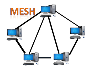
- Mesh technology is an arrangement of the network in which computers are interconnected with each other through various redundant connections.
- There are multiple paths from one computer to another computer.
- It does not contain the switch, hub or any central computer which acts as a central point of communication.
- The Internet is an example of the mesh topology.
- Mesh topology is mainly used for WAN implementations where communication failures are a critical concern.
- Mesh topology is mainly used for wireless networks.
- Mesh topology can be formed by using the formula:
Number of cables = (n*(n-1))/2;
Where n is the number of nodes that represents the network.
Mesh topology is divided into two categories:
- Fully connected mesh topology
- Partially connected mesh topology
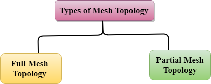
- Full Mesh Topology: In a full mesh topology, each computer is connected to all the computers available in the network.
- Partial Mesh Topology: In a partial mesh topology, not all but certain computers are connected to those computers with which they communicate frequently.
Advantages of Mesh topology:
Reliable: The mesh topology networks are very reliable as if any link breakdown will not affect the communication between connected computers.
Fast Communication: Communication is very fast between the nodes.
Easier Reconfiguration: Adding new devices would not disrupt the communication between other devices.
Disadvantages of Mesh topology
- Cost: A mesh topology contains a large number of connected devices such as a router and more transmission media than other topologies.
- Management: Mesh topology networks are very large and very difficult to maintain and manage. If the network is not monitored carefully, then the communication link failure goes undetected.
- Efficiency: In this topology, redundant connections are high that reduces the efficiency of the network.
Hybrid Topology
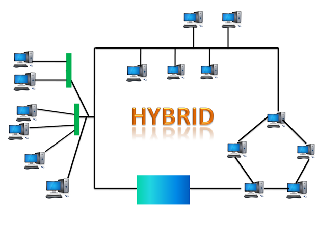
- The combination of various different topologies is known as Hybrid topology.
- A Hybrid topology is a connection between different links and nodes to transfer the data.
- When two or more different topologies are combined together is termed as Hybrid topology and if similar topologies are connected with each other will not result in Hybrid topology. For example, if there exist a ring topology in one branch of ICICI bank and bus topology in another branch of ICICI bank, connecting these two topologies will result in Hybrid topology.
Advantages of Hybrid Topology
- Reliable: If a fault occurs in any part of the network will not affect the functioning of the rest of the network.
- Scalable: Size of the network can be easily expanded by adding new devices without affecting the functionality of the existing network.
- Flexible: This topology is very flexible as it can be designed according to the requirements of the organization.
- Effective: Hybrid topology is very effective as it can be designed in such a way that the strength of the network is maximized and weakness of the network is minimized.
Disadvantages of Hybrid topology
- Complex design: The major drawback of the Hybrid topology is the design of the Hybrid network. It is very difficult to design the architecture of the Hybrid network.
- Costly Hub: The Hubs used in the Hybrid topology are very expensive as these hubs are different from usual Hubs used in other topologies.
- Costly infrastructure: The infrastructure cost is very high as a hybrid network requires a lot of cabling, network devices, etc.
Storage Device
What is a storage device?
Storage devices are the computer hardware used to remember/store data.
There are many types of storage devices, each with their own benefits and drawbacks.
Hard Disk Drive (HDD)
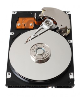
What is a hard disk drive?
Hard disk drives are non-volatile magnetic storage devices capable of remembering vast amounts of data.
An electromagnet in the read/write head charges the disk’s surface with either a positive or negative charge, this is how binary 1 or 0 is represented.
The read/write head is then capable of detecting the magnetic charges left on the disk’s surface, this is how data is read.
The disk surface is divided into concentric circles (tracks) and sectors (wedges). Dividing the surface in this way provides physical addresses to remember where data is saved.
A circuit board carefully co-ordinates the rotating disk and swinging actuator arm to allow the read/write head to access any location very quickly.
Typical HDD capacities are measured in Terabytes (TB).
They can be installed inside a computer or purchased in a portable (external) format.
Typical applications for hard disk drives
- Desktop computers
- Laptop computers
- TV and satellite recorders
- Servers and mainframes
- Portable (external) drives are sometimes used to backup home computers or transfer large files
Benefits of hard disk drives
- Capable of holding vast amounts of data at affordable prices
- Fast read and write speeds
- Reliable technology
- Relatively small in size
Drawbacks of hard disk drives
- Due to the nature of its moving parts, they will eventually wear and break
- Although very fast, waiting for the moving parts means it will never perform as fast as solid-state drives
- More fragile and less robust than a solid-state drive
- Higher power consumption than an SSD
- Some noise is created by the moving parts
Solid State Drive (SSD)

What is a solid-state drive?
Solid state drives are non-volatile storage devices capable of holding large amounts of data.
They use NAND flash memories (millions of transistors wired in a series on a circuit board), giving them the advantage of having no mechanical moving parts and therefore immediate access to the data.
Solid state drives perform faster than traditional hard disk drives, however they are significantly more expensive.
This expense means that typical capacities are usually measured in Gigabytes (GB).
They can be installed inside a computer or purchased in a portable (external) format.
Until we reach a point where large capacity SSDs is affordable, a compromise is to run two disk drives inside a computer. An SSD as the primary drive for your important programs and operating system, and a traditional HDD to store music, documents and pictures (which don’t need the faster access times).
The lack of moving parts in an SSD makes it very robust and reliable, ideal for a portable device.
Typical applications for solid state drives
- Smartphones
- Tablet computers
- High-end laptops
- Two drive desktop solutions
- Portable drives are sometimes used in HD video cameras
Benefits of solid-state drives
- Extremely fast read/write speeds
- Small in physical size and very light, ideal for portable devices
- No moving parts to wear, fail or get damaged – ideal for making portable computers and devices more reliable and durable
- Uses less power than an HDD, increasing battery life time
- Very quiet
- Generates less heat
Drawbacks of solid-state drives
- Expensive to buy (per GB)
- Limited in capacity due to the expense
- Limited amount of writes
Random Access Memory (RAM)
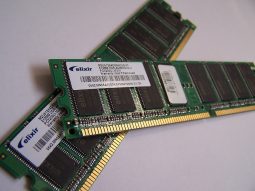
What is RAM?
RAM is a computer’s primary memory. It is a very fast solid-state storage medium that is directly accessible by the CPU.
Any open programs or files on a computer are temporarily stored in RAM whilst being used.
Being volatile, any data stored in RAM will be lost when power is removed. This makes RAM totally unsuitable for the long-term permanent storage of data – that is the role of an HDD or SSD instead.
Data is copied from secondary storage (HDD, SSD) to RAM as and when it is needed. This is because using an HDD as the primary memory would cause a computer to perform much slower (an HDD or SSD is not directly accessible to the CPU, and isn’t as fast as RAM).
RAM is a relatively expensive storage device and typical capacities are measured in Gigabytes (GB).
Computers operating with a capacity of RAM above the recommended minimum will benefit from better performance and multitasking.
There are two types of RAM (SRAM and DRAM), each with their own advantages and disadvantages.
Typical applications of RAM
- The fast and directly accessible temporary (working) memory needed by a computer
Benefits of RAM
- Directly accessible to the CPU, making processing data faster
- Fast solid-state storage, making processing data faster
Drawbacks of RAM
- Relatively expensive memory
- Volatile – any data stored in RAM is lost when power is removed
Static RAM (SRAM)
Data on SRAM does not require refreshing.
However, the technology is bulkier meaning less memory per chip.
- More expensive than DRAM
- Much faster than DRAM
- Consumes less power
- Commonly used in cache memory
Dynamic RAM (DRAM)
The most common type of RAM in use.
The data needs to be continually refreshed otherwise it fades away.
Continually refreshing the data takes time and reduces performance speeds.
- Cheaper than SRAM
- Commonly used in main memory
CD, DVD and Blu-Ray Discs

What are optical storage discs?
CD, DVD and Blue-ray drives are optical storage devices.
Binary data is stored as changes to the texture of the disc’s surface, sometimes thought of as microscopic pits and bumps.
These ‘bumps’ are located on a continuous spiral track, starting at the centre of the disc.
Whilst the disc is rotating at a constant speed, a laser is pointed at the spiral track of ‘bumps.
The laser will reflect/bounce off the disc surface in different directions depending upon whether a 1 or 0 has been read.
Disc capacities
In the pursuit of larger optical storage capacities, DVDs were created, followed by Blu-Ray.
CD | DVD | Blu-Ray |
700 MB | 4.7 GB | 25 GB – 128 GB |
Typical applications for optical media
- CD – Audio and small amounts of data
- DVD – Standard definition movies and data
- Blu-Ray – HD video and large amounts of data
DVD
Despite being the same physical size, a DVD can hold more data than a CD.
To achieve this, a more tightly packed spiral track is used to store the data on the disc.
To accurately access the smaller ‘bumps’, a finer red laser is used in a DVD drive than that found in a standard CD drive.
To increase capacity further, DVDs are also capable of dual layering.
Blu-Ray
Blu-Ray technology squashes even more data into the same size disc as a CD or DVD.
The spiral data tracks on a Blu-Ray disc are so small a special blue (violet) laser has to be used to read the ‘bumps.
Like a DVD, Blu-Ray discs are capable of storing data on multiple layers.
Recordable Optical Media
CD-ROM, DVD-ROM, Blu-Ray-ROM
Read only – the data is permanently written to the disc at the point of manufacture.
CD-R, DVD-R, BD-R
Recordable – blank discs that can be burnt (written to) once.
CD-RW, DVD-RW, BD-RE
Re-writable – blank discs that can be burnt (written to) over and over again (can be erased and reused many times).
DVD-RAM
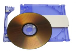
What is DVD-RAM?
DVD-RAM is an optical media storage device.
It differs from a traditional DVD in that data is stored in concentric tracks (like an HDD) which allows read and write operations to be carried out at the same time.
This means, for example, that when used in a personal video recorder you can record one television programme whilst watching a recording of another. This allows handy features such as ‘time slip’ to be possible.
When used within a CCTV system you could review footage whilst still recording your cameras.
The capacity of DVD-RAM is 4.7 GB, or 9.4 GB for double-sided discs.
Typical applications for DVD-RAM
- Personal and digital video recorders
- High-end CCTV
Benefits of DVD-RAM
- Read and write at the same time
- Can be rewritten to many more times than a traditional DVD-RW
- Has write-protect tabs to prevent accidental deletion when used in an optional cartridge
- Data is retained for an estimated 30 years. This long life is great for archiving data
- Reliable writing of discs because the verification done by the hardware, not by software
Drawbacks of DVD-RAM
- Disc speeds higher than 5x are less common
- Less compatibility than DVD-RW
ROM
What is ROM?
ROM is a non-volatile memory chip whose contents cannot be altered.
It is often used to store the start-up routines in a computer (e.g. The BIOS).
Typical applications for ROM
- Storing the computer’s start up routine
USB Flash Memory

What is USB Flash Memory?
Flash are non-volatile solid-state storage devices which use NAND flash memories to store data (millions of transistors).
USB refers to the USB connection that allows users to plug the device into the USB port of a computer.
Other types of flash storage include the memory cards used in digital cameras.
Flash memory comes in a variety of capacities to suit most budgets and requirements.
Typical applications for flash memory
- USB memory sticks – saving and transferring documents etc
- Memory cards in digital cameras
Benefits of flash memory
- Portable, small and lightweight
- Durability, flash has no moving parts to damage
- Range of capacities available
- Fast speeds, with no moving parts of boot up time
Drawbacks of flash memory
- Limited (but huge) number of write cycles possible
- Really high capacities are uncommon
- In relative terms, an expensive storage option compared to an HDD
Number System
The technique to represent and work with numbers is called number system. Decimal number system is the most common number system. Other popular number systems include binary number system, octal number system, hexadecimal number system, etc.
Decimal Number System
Decimal number system is a base 10 number system having 10 digits from 0 to 9. This means that any numerical quantity can be represented using these 10 digits. Decimal number system is also a positional value system. This means that the value of digits will depend on its position. Let us take an example to understand this.
Say we have three numbers – 734, 971 and 207. The value of 7 in all three numbers is different−
- In 734, value of 7 is 7 hundred or 700 or 7 × 100 or 7 × 10²
- In 971, value of 7 is 7 tens or 70 or 7 × 10 or 7 × 101
- In 207, value 0f 7 is 7 units or 7 or 7 × 1 or 7 × 100
The weightage of each position can be represented as follows −

In digital systems, instructions are given through electric signals; variation is done by varying the voltage of the signal. Having 10 different voltages to implement decimal number system in digital equipment is difficult. So, many number systems that are easier to implement digitally have been developed. Let’s look at them in detail.
Binary Number System
The easiest way to vary instructions through electric signals is two-state system – on and off. On is represented as 1 and off as 0, though 0 is not actually no signal but signal at a lower voltage. The number system having just these two digits – 0 and 1 – is called binary number system.
Each binary digit is also called a bit. Binary number system is also positional value system, where each digit has a value expressed in powers of 2, as displayed here.

In any binary number, the rightmost digit is called least significant bit (LSB) and leftmost digit is called most significant bit (MSB).
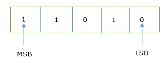
And decimal equivalent of this number is sum of product of each digit with its positional value.
110102 = 1×24 + 1×23 + 0×22 + 1×21 + 0×20
= 16 + 8 + 0 + 2 + 0
= 2610
Computer memory is measured in terms of how many bits it can store. Here is a chart for memory capacity conversion.
- 1 byte (B) = 8 bits
- 1 Kilobytes (KB) = 1024 bytes
- 1 Megabyte (MB) = 1024 KB
- 1 Gigabyte (GB) = 1024 MB
- 1 Terabyte (TB) = 1024 GB
- 1 Exabyte (EB) = 1024 PB
- 1 Zettabyte = 1024 EB
- 1 Yottabyte (YB) = 1024 ZB
Octal Number System
Octal number system has eight digits – 0, 1, 2, 3, 4, 5, 6 and 7. Octal number system is also a positional value system with where each digit has its value expressed in powers of 8, as shown here −

Decimal equivalent of any octal number is sum of product of each digit with its positional value.
7268 = 7×82 + 2×81 + 6×80
= 448 + 16 + 6
= 47010
Hexadecimal Number System
Octal number system has 16 symbols – 0 to 9 and A to F where A is equal to 10, B is equal to 11 and so on till F. Hexadecimal number system is also a positional value system with where each digit has its value expressed in powers of 16, as shown here −

Decimal equivalent of any hexadecimal number is sum of product of each digit with its positional value.
27FB16 = 2×163 + 7×162 + 15×161 + 10×160
= 8192 + 1792 + 240 +10
= 1023410
Number System Relationship
The following table depicts the relationship between decimal, binary, octal and hexadecimal number systems.
HEXADECIMAL | DECIMAL | OCTAL | BINARY |
0 | 0 | 0 | 0000 |
1 | 1 | 1 | 0001 |
2 | 2 | 2 | 0010 |
3 | 3 | 3 | 0011 |
4 | 4 | 4 | 0100 |
5 | 5 | 5 | 0101 |
6 | 6 | 6 | 0110 |
7 | 7 | 7 | 0111 |
8 | 8 | 10 | 1000 |
9 | 9 | 11 | 1001 |
A | 10 | 12 | 1010 |
B | 11 | 13 | 1011 |
C | 12 | 14 | 1100 |
D | 13 | 15 | 1101 |
E | 14 | 16 | 1110 |
F | 15 | 17 | 1111 |
Inter conversion number system
There are many methods or techniques which can be used to convert numbers from one base to another. In this chapter, we'll demonstrate the following −
- Decimal to Other Base System
- Other Base System to Decimal
- Other Base System to Non-Decimal
- Shortcut method - Binary to Octal
- Shortcut method - Octal to Binary
- Shortcut method - Binary to Hexadecimal
- Shortcut method - Hexadecimal to Binary
Decimal to Other Base System
Step 1 − Divide the decimal number to be converted by the value of the new base.
Step 2 − Get the remainder from Step 1 as the rightmost digit (least significant digit) of the new base number.
Step 3 − Divide the quotient of the previous divide by the new base.
Step 4 − Record the remainder from Step 3 as the next digit (to the left) of the new base number.
Repeat Steps 3 and 4, getting remainders from right to left, until the quotient becomes zero in Step 3.
The last remainder thus obtained will be the Most Significant Digit (MSD) of the new base number.
Example
Decimal Number: 2910
Calculating Binary Equivalent −
Step | Operation | Result | Remainder |
Step 1 | 29 / 2 | 14 | 1 |
Step 2 | 14 / 2 | 7 | 0 |
Step 3 | 7 / 2 | 3 | 1 |
Step 4 | 3 / 2 | 1 | 1 |
Step 5 | 1 / 2 | 0 | 1 |
As mentioned in Steps 2 and 4, the remainders have to be arranged in the reverse order so that the first remainder becomes the Least Significant Digit (LSD) and the last remainder becomes the Most Significant Digit (MSD).
Decimal Number : 2910 = Binary Number : 111012.
Other Base System to Decimal System
Step 1 − Determine the column (positional) value of each digit (this depends on the position of the digit and the base of the number system).
Step 2 − Multiply the obtained column values (in Step 1) by the digits in the corresponding columns.
Step 3 − Sum the products calculated in Step 2. The total is the equivalent value in decimal.
Example
Binary Number: 111012
Calculating Decimal Equivalent −
Step | Binary Number | Decimal Number |
Step 1 | 111012 | ((1 x 24) + (1 x 23) + (1 x 22) + (0 x 21) + (1 x 20))10 |
Step 2 | 111012 | (16 + 8 + 4 + 0 + 1)10 |
Step 3 | 111012 | 2910 |
Binary Number : 111012 = Decimal Number : 2910
Other Base System to Non-Decimal System
Step 1 − Convert the original number to a decimal number (base 10).
Step 2 − Convert the decimal number so obtained to the new base number.
Example
Octal Number : 258
Calculating Binary Equivalent −
Step 1 - Convert to Decimal
Step | Octal Number | Decimal Number |
Step 1 | 258 | ((2 x 81) + (5 x 80))10 |
Step 2 | 258 | (16 + 5)10 |
Step 3 | 258 | 2110 |
Octal Number : 258 = Decimal Number : 2110
Step 2 - Convert Decimal to Binary
Step | Operation | Result | Remainder |
Step 1 | 21 / 2 | 10 | 1 |
Step 2 | 10 / 2 | 5 | 0 |
Step 3 | 5 / 2 | 2 | 1 |
Step 4 | 2 / 2 | 1 | 0 |
Step 5 | 1 / 2 | 0 | 1 |
Decimal Number : 2110 = Binary Number : 101012
Octal Number : 258 = Binary Number : 101012
Shortcut Method ─ Binary to Octal
Step 1 − Divide the binary digits into groups of three (starting from the right).
Step 2 − Convert each group of three binary digits to one octal digit.
Example
Binary Number : 101012
Calculating Octal Equivalent −
Step | Binary Number | Octal Number |
Step 1 | 101012 | 010 101 |
Step 2 | 101012 | 28 58 |
Step 3 | 101012 | 258 |
Binary Number : 101012 = Octal Number : 258
Shortcut Method ─ Octal to Binary
Step 1 − Convert each octal digit to a 3-digit binary number (the octal digits may be treated as decimal for this conversion).
Step 2 − Combine all the resulting binary groups (of 3 digits each) into a single binary number.
Example
Octal Number : 258
Calculating Binary Equivalent −
Step | Octal Number | Binary Number |
Step 1 | 258 | 210 510 |
Step 2 | 258 | 0102 1012 |
Step 3 | 258 | 0101012 |
Octal Number : 258 = Binary Number : 101012
Shortcut Method ─ Binary to Hexadecimal
Step 1 − Divide the binary digits into groups of four (starting from the right).
Step 2 − Convert each group of four binary digits to one hexadecimal symbol.
Example
Binary Number : 101012
Calculating hexadecimal Equivalent −
Step | Binary Number | Hexadecimal Number |
Step 1 | 101012 | 0001 0101 |
Step 2 | 101012 | 110 510 |
Step 3 | 101012 | 1516 |
Binary Number : 101012 = Hexadecimal Number : 1516
Shortcut Method - Hexadecimal to Binary
Step 1 − Convert each hexadecimal digit to a 4-digit binary number (the hexadecimal digits may be treated as decimal for this conversion).
Step 2 − Combine all the resulting binary groups (of 4 digits each) into a single binary number.
Example
Hexadecimal Number : 1516
Calculating Binary Equivalent −
Step | Hexadecimal Number | Binary Number |
Step 1 | 1516 | 110 510 |
Step 2 | 1516 | 00012 01012 |
Step 3 | 1516 | 000101012 |
Hexadecimal Number : 1516 = Binary Number : 101012
We can perform addition and subtraction using 1's, 2's, 9's, and 10's complement.
Addition using 1's complement
There are three different cases possible when we add two binary numbers which are as follows:
Case 1: Addition of the positive number with a negative number when the positive number has a greater magnitude.
Initially, calculate the 1's complement of the given negative number. Sum up with the given positive number. If we get the end-around carry 1, it gets added to the LSB.
Example: 1101 and -1001
- First, find the 1's complement of the negative number 1001. So, for finding 1's complement, change all 0 to 1 and all 1 to 0. The 1's complement of the number 1001 is 0110.
- Now, add both the numbers, i.e., 1101 and 0110;
1101+0110=1 0011 - By adding both numbers, we get the end-around carry 1. We add this end around carry to the LSB of 0011.
0011+1=0100
Case 2: Adding a positive value with a negative value in case the negative number has a higher magnitude.
Initially, calculate the 1's complement of the negative value. Sum it with a positive number. In this case, we did not get the end-around carry. So, take the 1's complement of the result to get the final result.
Note: The resultant is a negative value.
Example: 1101 and -1110
- First find the 1's complement of the negative number 1110. So, for finding 1's complement, we change all 0 to 1, and all 1 to 0. 1's complement of the number 1110 is 0001.
- Now, add both the numbers, i.e., 1101 and 0001;
1101+0001= 1110 - Now, find the 1's complement of the result 1110 that is the final result. So, the 1's complement of the result 1110 is 0001, and we add a negative sign before the number so that we can identify that it is a negative number.
Case 3: Addition of two negative numbers
In this case, first find the 1's complement of both the negative numbers, and then we add both these complement numbers. In this case, we always get the end-around carry, which get added to the LSB, and for getting the final result, we take the 1's complement of the result.
Note: The resultant is a negative value.
Example: -1101 and -1110 in five-bit register
- Firstly, find the 1's complement of the negative numbers 01101 and 01110. So, for finding 1's complement, we change all 0 to 1, and all 1 to 0. 1's complement of the number 01110 is 10001, and 01101 is 10010.
- Now, we add both the complement numbers, i.e., 10001 and 10010;
10001+10010= 1 00011 - By adding both numbers, we get the end-around carry 1. We add this end-around carry to the LSB of 00011.
00011+1=00100 - Now, find the 1's complement of the result 00100 that is the final answer. So, the 1's complement of the result 00100 is 110111, and add a negative sign before the number so that we can identify that it is a negative number.
Subtraction using 1's complement
These are the following steps to subtract two binary numbers using 1's complement
- In the first step, find the 1's complement of the subtrahend.
- Next, add the complement number with the minuend.
- If got a carry, add the carry to its LSB. Else take 1's complement of the result which will be negative
Note: The subtrahend value always gets subtracted from minuend.
Example 1: 10101 - 00111
We take 1's complement of subtrahend 00111, which comes out 11000. Now, sum them. So,
10101+11000 =1 01101.
In the above result, we get the carry bit 1, so add this to the LSB of a given result, i.e., 01101+1=01110, which is the answer.
Example 2: 10101 - 10111
We take 1's complement of subtrahend 10111, which comes out 01000. Now, add both of the numbers. So,
10101+01000 =11101.
In the above result, we didn't get the carry bit. So, calculate the 1's complement of the result, i.e., 00010, which is the negative number and the final answer.
We will learn to perform these operations using 2's complement.
Addition using 2's complement
There are three different cases possible when we add two binary numbers using 2's complement, which is as follows:
Case 1: Addition of the positive number with a negative number when the positive number has a greater magnitude.
Initially find the 2's complement of the given negative number. Sum up with the given positive number. If we get the end-around carry 1 then the number will be a positive number and the carry bit will be discarded and remaining bits are the final result.
Example: 1101 and -1001
- First, find the 2's complement of the negative number 1001. So, for finding 2's complement, change all 0 to 1 and all 1 to 0 or find the 1's complement of the number 1001. The 1's complement of the number 1001 is 0110, and add 1 to the LSB of the result 0110. So, the 2's complement of number 1001 is 0110+1=0111
- Add both the numbers, i.e., 1101 and 0111;
1101+0111=1 0100 - By adding both numbers, we get the end-around carry 1. We discard the end-around carry. So, the addition of both numbers is 0100.
Case 2: Adding of the positive value with a negative value when the negative number has a higher magnitude.
Initially, add a positive value with the 2's complement value of the negative number. Here, no end-around carry is found. So, we take the 2's complement of the result to get the final result.
Note: The resultant is a negative value.
Example: 1101 and -1110
- First, find the 2's complement of the negative number 1110. So, for finding 2's complement, add 1 to the LSB of its 1's complement value 0001.
0001+1=0010 - Add both the numbers, i.e., 1101 and 0010;
1101+0010= 1111 - Find the 2's complement of the result 1110 that is the final result. So, the 2's complement of the result 1110 is 0001, and add a negative sign before the number so that we can identify that it is a negative number.
Case 3: Addition of two negative numbers
In this case, first, find the 2's complement of both the negative numbers, and then we will add both these complement numbers. In this case, we will always get the end-around carry, which will be added to the LSB, and forgetting the final result, we will take the2's complement of the result.
Note: The resultant is a negative value.
Example: -1101 and -1110 in five-bit register
- Firstly, find the 2's complement of the negative numbers 01101 and 01110. So, for finding 2's complement, we add 1 to the LSB of the 1's complement of these numbers. 2's complement of the number 01110 is 10010, and 01101 is 10011.
- We add both the complement numbers, i.e., 10001 and 10010;
10010+10011= 1 00101 - By adding both numbers, we get the end-around carry 1. This carry is discarded and the final result is the 2.s complement of the result 00101. So, the 2's complement of the result 00101 is 11011, and we add a negative sign before the number so that we can identify that it is a negative number.
Subtraction using 2's complement
These are the following steps to subtract two binary numbers using 2's complement
- In the first step, find the 2's complement of the subtrahend.
- Add the complement number with the minuend.
- If we get the carry by adding both the numbers, then we discard this carry and the result is positive else take 2's complement of the result which will be negative.
Example 1: 10101 - 00111
We take 2's complement of subtrahend 00111, which is 11001. Now, sum them. So,
10101+11001 =1 01110.
In the above result, we get the carry bit 1. So, we discard this carry bit and remaining is the final result and a positive number.
Example 2: 10101 - 10111
We take 2's complement of subtrahend 10111, which comes out 01001. Now, we add both of the numbers. So,
10101+01001 =11110.
In the above result, we didn't get the carry bit. So, calculate the 2's complement of the result, i.e., 00010. It is the negative number and the final answer.
Text Books:
1. Satinder Bal Gupta & Amit Singla, Fundamental of Computers and Programming in C, Shree Mahavir Book (Publishers), New Delhi
2. Ajay Mittal, Programming in C, ‘A Practical Approach’, Pearson Education.
3. Byron Gottfried, Schaum's Outline of Programming with C, McGraw-Hill
4. E. Balaguruswamy, Programming in ANSI C, Tata McGraw-Hill
5. YashavantKanetkar, Let Us C, BPB Publication.