Unit 1
DC Circuits
DC NETWORKS
The algebraic sum of currents meeting at a junction or node in a electric circuit is zero or the summation of all incoming current is always equal to summation of all outgoing current in an electrical network.
Explanation
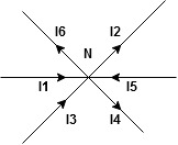
Assuming the incoming current to be positive and outgoing current negative we have


I e incoming current = ∑ outgoing current thus, the above Law can also be stated as the sum of current flowing towards any junction in an electric circuit is equal to the sum of currents flowing away from that junction
Kirchhoff’s Voltage Law (KVL)
Statement : the algebraic summation of all Voltage in any closed circuit or mesh of loop zero.
Ie ∑ Voltage in closed loop = 0 the summation of the Voltage rise (voltage sources) is equal to summation of the voltage drops around a closed loop in 0 circuit for explanation from here
Determination of sigh and direction of currents (Don’t write in exams just for understanding)

Current entering a resistor is +ve and leaving should be –ve
Now
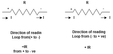


Potential Rise Potential Drop
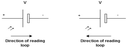
We are reading from +V to –V we are reading from –V to +V
 potential drops
  potential rise
 -V
-V  +V
+V
Given Circuit
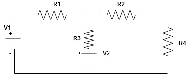
First identify no of loops and assign direction of current flowing in loop
Note : no of loops in circuit = No, of unknown currents = no, of equations in the circuit
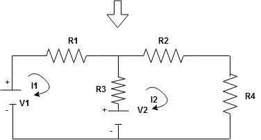
Note : keep loop direction and current direction same ie either clockwise or anticlockwise for all loops I1 I2
Now according to direction of direction assign signs (+ve to –ve) to the resistors
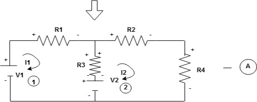
Note : voltage sources (V) polarities does not change is constant.
Note: for common resistor between 2 loops appearing in the circuit like R3 give signs according to separate loops as shown
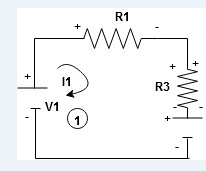
When considering only loop no 1 (+ R3 - )
- B
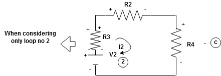
Now consider diagram A and write equations
Two loops  two unknown currents
  two equation
Apply KVL for loop ① [B. Diagram ]
(+ to drop -) = - sign and (- to rise +) = + sign
 for drop = -sign
 for rise = + sign
-
-( ) R2 is considered because in R3,2 currents are flowing
  and
and  and we have taken (
 ) because we are considering loop no 1 and current flowing is
  in loop no 1
 )
)
Similarly for loop no. 2 currents flowing is  resistor R3 it should be
  )R3
)R3
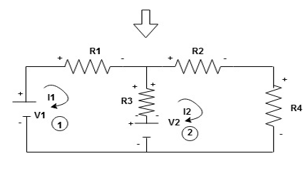
Consider loop no. 1 apply KVL
- …….①
…….①
-
Consider loop no. 2 apply KVL
- …….②
…….②
-
After solving equation ① and ② we will get branch current  and
and 
NODE ANALYSIS
For these we assume every node as a voltage point and write the current equation for every element. For current source, current entering is negative.
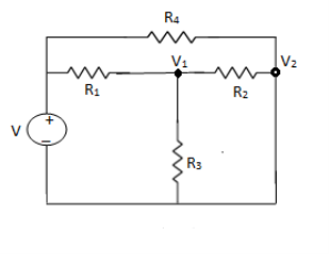
For node V1

For node V2

For V

Example: Using nodal analysis find voltage across 5resistor.
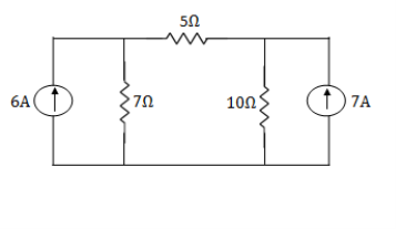
Solution:
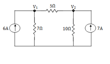
For V1


 1
1
For V2


 2
2
Solving 1 and 2:


For 5 voltage = 
= -50.9 + 57.27
= 6.37V
Mesh analysis:
Mesh analysis technique, uses mesh currents as variables , instead of currents in the elements to analyse the circuit. Therefore, this method absolutely reduces the number of equations to be solved .
Mesh analysis applies the Kirchhoff’s Voltage Law (KVL) to determine the unknown currents in a given circuit.
Mesh analysis is also called as mesh-current method or loop analysis. After finding the mesh currents using KVL, voltages anywhere in a given circuit can be determined by using Ohms law.
Steps to Analyse the mesh analysis technique
1) Check whether there is a possibility to transform all current sources in the given circuit to voltage sources.
2) Assign the current directions to each mesh in a given circuit and follow the same direction for each mesh.
3) Apply KVL to each mesh and simplify the KVL equations.
4) Solve the simultaneous equations of various meshes to get the mesh currents and these equations are exactly equal to the number of meshes present in the network.
Consider the below DC circuit to apply the mesh current analysis, such that currents in different meshes can be found. In the below figure there are three meshes present as ACDA, CBDC and ABCA but the path ABDA is not a mesh. As a first step, the current through each mesh is assigned with the same direction as shown in figure.
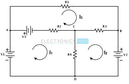
Secondly, for each mesh we have to apply KVL. By applying KVL around the first loop or mesh we get
V1 − V3 − R2 ( I1 − I 3 ) − R4 ( I1 − I 2 ) = 0
V1 − V3 = I1 ( R2 + R4 ) − I2R4 − I3R2 ………………(1)
Similarly , by applying KVL around second mesh we get,
−V2 − R3 ( I 2 − I 3 ) − R4 ( I 2 − I1 ) = 0
− V2 = − I1R4 + I 2 ( R3 + R4 ) − I 3 R3 ………………………(2)
And by applying KVL around third mesh or loop we get,
V3 − R1I 3 − R3( I 3 − I 2 ) − R2( I 3 − I1 ) = 0
V3 = − I1R2 − I2R3 + I3(R1 + R2 + R3) ………………………(3)
Therefore, by solving the above three equations we can obtain the mesh currents for each mesh in the given circuit.
Star to delta conversion to final equivalent resistance
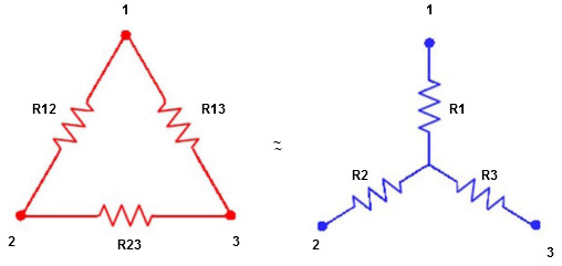
We know that (from delta to star conversion)
R1 =  …….①
…….①
R2 =  …..②
…..②
R1 =  ……③
……③
Multiply ① X ② L.H.S and R.H.S
R1 R2 =  …….④ where
Similarly multiply ② X ③
R2 R3 =  …….⑤
…….⑤
And ③ X①
R1 R3 =  …….⑥
…….⑥
Now add equation ④, ⑤, and ⑥ L.H.S and R.H.S


 ……refer eq. ②
 =
=  +
+  +
+ 
 =
=  +
+ 

(Delta) star star
Similarly R23 = R2+R3 + 
R23 = R1+R2 + 
- Delta to Star Conversion to Find (Req.)
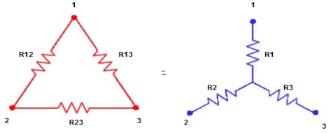
- Equivalent resistance between ① and ②
Delta  Star
Star
= R12// (R23 + R13) =R1 + R2
= 
 = R1 + R2
= 

Here let R = R12 + R23 + R13
- Similarly we can find Req. Between 2 and 3
= 
 R2 + R3
- Similarly we can find req. Between 1 and 3

 R1 + R3
Now the 3 equations after equating L.H.S. And R.H.S
R1 + R2 =  …….①
…….①
R2 + R3 =  ……②
……②
R1 + R3 =  …..③
…..③
Now subtract ② and ① on L.H.S. And R.H.S
R2+ R3 – R1 – R2 = 
 R3 – R1 =
  …..④
…..④
Now add equation ④ and ③
R3 – R1 + R1 + R3 = 
2R3 = 

Similarly R1 = 
And R2 = R23 R12/R where R = R12 + R23 + R13
Ie star equivalent from delta network is ratio of product of adjacent branches in delta to the addition of all branches in delta.
Superposition Theorem
- This is only applicable to circuits with linear elements.
- If two or more than two independent sources (voltage or current) are operating in the circuit than voltage across any element or current through any element is sum of current and voltages due to individual sources.
Question 1. Find the current through  resistance.
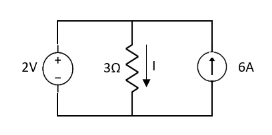
Solution:
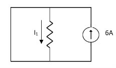
 1= 0
1= 0
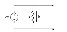
 2=
2=
 1 +
1 +  2
2 
Special Case:
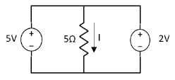
Since two voltage sources with different magnitude in parallel which cannot be connected as in single branch two different current is not possible (if 5V than I = zero).
Question:
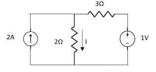
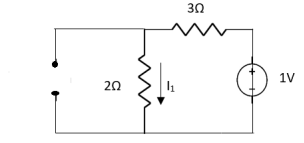
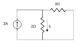
 1 =
1 = 
 2 =
2 = 
=
 1 +
1 +  2
2
= 
Thevenin’s and Norton’s Theorem

Thevenin’s equivalent of A
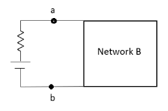
Norton’s equivalent of A
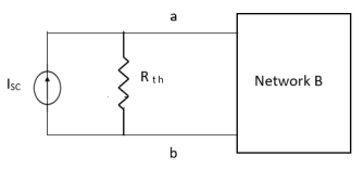
 sc = Vth/Rth
- Norton’s equivalent is obtained by source conversion of thevenin’s equivalent circuit.
Transients in R-L
Consider the following series RL circuit diagram.
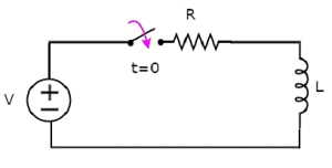
In the above circuit, the switch was kept open up to t = 0 and it was closed at t = 0. So, the DC voltage source having V volts is not connected to the series RL circuit up to this instant. Therefore, there is no initial current flows through inductor.
The circuit diagram, when the switch is in closed position is shown in the following figure.
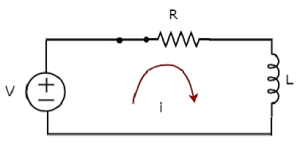
Now, apply KVL around the loop.
V=Ri+ L di/dt
Di/dt+⟮R/L⟯i=VL Equation 1
The above equation is a first order differential equation and it is in the form of
Dy/dt+Py=Q Equation 2
By comparing Equation 1 and Equation 2, we will get the following relations.
x=t
y=i
P=R/L
Q = V/L
The solution of Equation 2 will be
Ye∫pdx=∫Qe∫pdxdx+k-------------------------Equation 3
Where, k is the constant.
Substitute, the values of x, y, P & Q in Equation 3.
Ie∫⟮R/L⟯dt=∫(V/L)⟮e∫⟮R/L⟯dt⟯dt+k
⇒ie⟮R/L⟯t=V/L∫e⟮R/L⟯tdt+k
⇒ie⟮R/L⟯t=V/L{e⟮R/L⟯t/R/L}+k
⇒i=V/R+ke−⟮R/L⟯t--------------------------Equation 4
We know that there is no initial current in the circuit.
Hence, substitute, t = 0 and 𝑖 = 0 in Equation 4 in order to find the value of the constant k.
0=V/R+ke−⟮R/L⟯(0)0=
0=VR+k(1)
k=−V/R
Substitute, the value of k in Equation 4.
i=V/R+⟮−V/R⟯e−⟮R/L⟯t
i=V/R−V/Re−⟮R/L⟯t
Therefore, the current flowing through the circuit is
i=−V/R e−⟮R/L⟯t+V/R Equation 5
So, the response of the series RL circuit, when it is excited by a DC voltage source, has the following two terms.
- The first term −V/ R e−⟮R/L⟯t corresponds with the transient response.
- The second term V/R corresponds with the steady state response.
- These two responses are shown in the following figure.
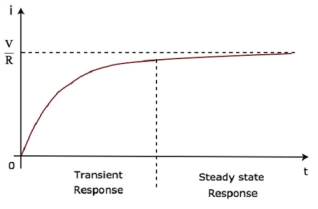
We can re-write the Equation 5 as follows −
i=V/R⟮1−e−⟮R/L⟯t⟯
⇒i=VR⟮1−e−⟮tτ ) Equation 6
Where, τ is the time constant and its value is equal to LR.
Both Equation 5 and Equation 6 are same. But, we can easily understand the above waveform of current flowing through the circuit from Equation 6 by substituting a few values of t like 0, τ, 2τ, 5τ, etc.
If a sinusoidal signal is applied as an input to a Linear electric circuit, then it produces a steady state output, which is also a sinusoidal signal. Both the input and output sinusoidal signals will be having the same frequency, but different amplitudes and phase angles.
We can calculate the steady state response of an electric circuit, when it is excited by a sinusoidal voltage source using Laplace Transform approach.
The s-domain circuit diagram, when the switch is in closed position, is shown in the following figure.
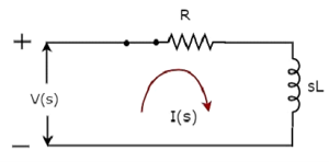
In the above circuit, all the quantities and parameters are represented in s-domain. These are the Laplace transforms of time-domain quantities and parameters.
The Transfer function of the above circuit is
H(s)=I(s)V(s)
⇒H(s)=1Z(s
⇒H(s)=1R+sL
Substitute s=jω in the above equation.
H(jω)=1R+jωL
Magnitude of H(jω) is
|H(jω)|=1R2+ω2−−−−−−−√L2|H(jω)|=1R2+ω2L2
Phase angle of H(jω) is
∠H(jω)=−tan−1⟮ωL/R)
We will get the steady state current iss(t) by doing the following two steps −
- Multiply the peak voltage of input sinusoidal voltage and the magnitude of H(jω)
- Add the phase angles of input sinusoidal voltage and H(jω).
The steady state current iss(t) will be
Iss(t)=Vm/ R2+ω2L2 (sin⟮ωt+φ−tan−1⟮ωL/R⟯⟯
Substitute the value of iss(t) in Equation 2.
i(t)=Ke−⟮t/τ⟯+Vm/  R2+ω2L2 sin⟮ωt+φ−tan−1⟮ωL/R⟯⟯ --------------Equation 3
We know that there is no initial current in the circuit.
Hence, substitute t = 0 & i(t) = 0 in Equation 3 in order to find the value of constant, K.
0=Ke−⟮0τ⟯+Vm /  R2+ω2L2 [sin⟮ω(0)+φ−tan−1⟮ωL/R⟯
⇒0=K+Vm/  R2+ω2L2 sin⟮φ−tan−1⟮ωL/R)
⇒K=−Vm/  R2+ω2L2 sin⟮φ−tan−1⟮ωL/R)
Substitute the value of K in Equation 3.
i(t)=−Vm/ R2+ω2L2sin⟮φ−tan−1⟮ωL/R⟯⟯e−⟮t/τ⟯+Vm/
 R2+ω2L2sin⟮ωt+φ−tan−1⟮ωL/R⟯⟯
-----------------Equation 4
Equation 4 represents the current flowing through the series RL circuit, when it is excited by a sinusoidal voltage source. It is having two terms. The first and second terms represent the transient response and steady state response of the current respectively.
We can neglect the first term of Equation 4 because its value will be very much less than one. So, the resultant current flowing through the circuit will be
i(t)=Vm/  R2+ω2L2 sin⟮ωt+φ−tan−1⟮ωL/R⟯
It contains only the steady state term. Hence, we can find only the steady state response of AC circuits and neglect transient response of it.
Transient response:
The transient response time T is measured in terms of τ = R x C, in seconds, where R is the value of the resistor in ohms and C is the value of the capacitor in Farads. This then forms the basis of an RC charging circuit were 5T can also be thought of as “5 x RC”.
RC Charging Circuit
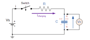
The figure below shows a capacitor, (C ) in series with a resistor, ( R ) forming a RC Charging Circuit connected across a DC battery supply ( Vs ) via a mechanical switch. At time zero, when the switch is first closed, the capacitor gradually charges up through the resistor until the voltage across it reaches the supply voltage of the battery.
RC Charging Circuit
Let us assume above, that the capacitor, C is fully “discharged” and the switch (S) is fully open. These are the initial conditions of the circuit, then t = 0, i = 0 and q = 0. When the switch is closed the time begins at t = 0 and current begins to flow into the capacitor via the resistor.
Since the initial voltage across the capacitor is zero, ( Vc = 0 ) at t = 0 the capacitor appears to be a short circuit to the external circuit and the maximum current flows through the circuit restricted only by the resistor R.
Then by using Kirchhoff’s voltage law (KVL), the voltage drops around the circuit are given as:
Vs – R x i(t) – Vc(t) =0.
The current now flowing around the circuit is called the Charging Current and is found by using Ohms law as: i = Vs/R.
RC Charging Circuit Curves
As the capacitor charges up as shown, the rise in the RC charging curve is steeper at the beginning because the charging rate is fastest at the start and then tapers off as the capacitor takes on additional charge at a slower rate.
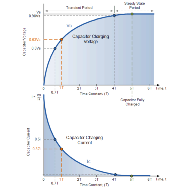
As the capacitor charges up, the potential difference across its plates slowly increases with the actual time taken for the charge on the capacitor to reach 63% of its maximum possible voltage, in our curve 0.63Vs being known as one Time Constant, ( T ).
This 0.63Vs voltage point is given the abbreviation of 1T, (one time constant).
The capacitor continues charging up and the voltage difference between Vs and Vc reduces, so too does the circuit current, i. Then at its final condition greater than five time constants ( 5T ) when the capacitor is said to be fully charged, t = ∞, i = 0, q = Q = CV.
At infinity the charging current finally diminishes to zero and the capacitor acts like an open circuit with the supply voltage value entirely across the capacitor as Vc = Vs.
So mathematically we can say that the time required for a capacitor to charge up to one time constant, ( 1T ) is given as:
RC Time Constant,
τ= R x C
This RC time constant only specifies a rate of charge where, R is in Ω and C in Farads.
Since voltage V is related to charge on a capacitor given by the equation, Vc = Q/C, the voltage across the capacitor ( Vc ) at any instant in time during the charging period is given as:
Vc = Vs(1- e(-t/RC))
Where:
Vc is the voltage across the capacitor
Vs is the supply voltage
t is the elapsed time since the application of the supply voltage
RC is the time constant of the RC charging circuit.
After a period equivalent to 4 time constants, ( 4T ) the capacitor in this RC charging circuit is virtually fully charged and the voltage across the capacitor is now approx 98% of its maximum value, 0.98Vs. The time period taken for the capacitor to reach this 4T point is known as the Transient Period.
After a time of 5T the capacitor is now said to be fully charged with the voltage across the capacitor, ( Vc ) being equal to the supply voltage, ( Vs ). As the capacitor is fully charged no more current flows in the circuit. The time period after this 5T point is known as the Steady State Period.
Series R-L-C circuit:
The circuit shown is called series R-L-C circuit. When the switch is closed the equation describes the response of the system by applying KVL around the mesh.
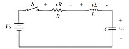
VR + vL + vc = Vs -----------------------------(1)
The current flowing in the circuit is
i = C dvc/dt -----------------------------(2)
Thus, the voltages vR and vL are given by
VR = iR = RC dvc/dt ----------------------------------(3)
VL = L di/dt = LC d2vc/dt2 -----------------------------------------(4)
Substituting eq (3) and (4) in (1) we get
d 2 vc/dt 2 + R/L dvc/dt + 1/LC vc = 1/LC Vs ---------------------------(5)
The solution to equation(5) is the linear combination of the homogeneous and the particular solution vc = vcp + vch
The particular solution is
Vcp=vs --------------------------------------------(6)
And the homogeneous solution satisfies the equation
d 2 vch/dt2 + R/L d vch/dt + 1/LC vch =0 ----------------------------(7)
Assuming the homogeneous solution is of the form Ae st and by substituting into equation(7) we get
s 2 + R/L s + 1/LC =0 ------------------------------(8)
By defining α = R/2L ; Damping rate ----------------------------(9)
w0 = 1/  : Natural frequency.-------------------------(10)
The characteristic equation becomes
s 2 + 2 α s + wo 2 = 0 -------------------------------------(11)
The roots of the characteristic equation are :
s 1 = -α +  2 – wo 2 --------------------------------------------(12)
s2 = -α -  2 – wo 2 --------------------------------------------------------------------(13)
And the homogeneous solution becomes
Vch = A1 e s1t + A2 e s2t ----------------------------------------------------------(14)
The total solution is
Vc = Vs + A1 e s1t + A2 es2t ------------------------------------------------------------------(15)
The parameters A1 and A2 are constants and can be determined by the application of the initial conditions of the system vc(t=0) and dvc(t)/dt
The value of the  2 – wo 2 determine the behaviour of the response.
α = wo then s1 and s2 are equal and real numbers ; no oscillatory behaviour
Critically Damped System.
α>wo and s1 and sr are real numbers but not equal and no oscillatory behaviour then it is over damped system.
Vc = Vs + A1 es1t + A2 e s2t
α<wo  2 – wo 2 = j
  2 – α 2 . In this case the roots s1 and s2 are complex numbers.
s 1 = - α + j  2 – α 2
s2 = - α - j  2 – α 2
The system exhibits underdamped system.
SINGLE PHASE AC CIRCUITS
EMF equation for 1ø transformer:-
Consider ac sinusoidal flux,
Ø=Øm sinwt
By faraday’s law of electromagnetic induction EMF induced is, for a single turn.
e=−d∅dt
For N, number of turn
e=−N . d∅dt
e = N ((−d∅dt ∅m sinwt)
=N∅mcoswtw
=−N∅m2πfcoswt
e=∅mN.2πsin(wt−π2)
Emax=N.∅m2πf
ERMS =emax2–√=4.44NN∅mf
Primary induced emf,E1=4.44N1∅mf
E2=4.44N2∅mf
The average of all the instantaneous values of an alternating voltage and currents over one complete cycle is called Average Value.
If we consider symmetrical waves like sinusoidal current or voltage waveform, the positive half cycle will be exactly equal to the negative half cycle. Therefore, the average value over a complete cycle will be zero.
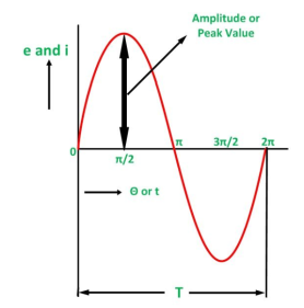
The work is done by both, positive and negative cycle and hence the average value is determined without considering the signs.
So, the only positive half cycle is considered to determine the average value of alternating quantities of sinusoidal waves. Let us take an example to understand it.
Divide the positive half cycle into (n) number of equal parts as shown in the above figure
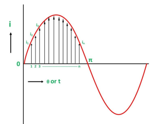
Let i1, i2, i3…….. in be the mid ordinates
The average value of current I av = mean of the mid ordinates
Iav = i1+i2 + i3 ………………….+in/n = Area of alternation / Base
- In electrical engineering this type of number is called an “imaginary number” and to distinguish an imaginary number from a real number the letter “ j ” known commonly in electrical engineering as the j-operator, is used.
- Thus, the letter “j” is placed in front of a real number to signify its imaginary number operation.
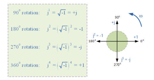
- The j-operator has a value exactly equal to √-1, so successive multiplication of “ j “, ( j x j ) will result in j having the following values of, -1, -j and +1.
- As the j-operator is commonly used to indicate the anticlockwise rotation of a vector, each successive multiplication or power of “ j “, j2, j3 etc, will force the vector to rotate through a fixed angle of 90o in an anticlockwise direction as shown below. Likewise, if the multiplication of the vector results in a -j operator then the phase shift will be -90o, i.e. a clockwise rotation.
Vector rotation of j operator:
The amplitude of the current is linearly related to the amplitude of the voltage, but the phase angle is determined by a trigonometric equation.
These relations can be very conveniently combined into a single linear relation by expressing the voltage and current as the real parts of complex quantities
Vˆ = Vˆ 0 exp(iωt) and ˆI = ˆI0 exp(iωt), (1)
With Vˆ 0 = V0 and
ˆI0 = I0e −iφ.
We use the hat notation to indicate a quantity that is a complex number.
The impedance Z is defined as the ratio of the complex voltage and current amplitudes:
Z = Vˆ 0/ ˆI0 = V0/ I0 e iφ . (2)
(Since Z is almost always complex we don’t bother to put a hat on it.)
The complex voltage Vˆ and current ˆI (1) thus obey the linear relation Vˆ = ˆIZ, which is a complex generalization of Ohm’s law, V = IR.
The impedance is most directly interpreted when written in polar form, Z = |Z|e iφ . The magnitude |Z| = V0/I0 is called the reactance, and it determines the real amplitude of the current given the real amplitude of the voltage.
The phase φ of Z encodes the phase relation between voltage V0 cos ωt and current I0 cos(ωt − φ).
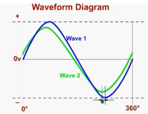
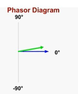
A phasor diagram is used to show the phase relationships between two or more sine waves having the same frequency.
Every phasor in the diagram will have the same angular velocity because they represent sine waves of identical frequency. The length of the each phasor arm is directly related to the amplitude of the wave it represents, and the angle between the phasors is the same as the angle of phase difference between the sine waves.
Figure shows how a phasor diagram is used to illustrate the phase difference between waves 1 and 2.
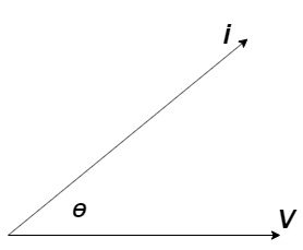
It is the cosine of angle between voltage and current

If Ɵis –ve or lagging (I lags V) then lagging P.F.
If Ɵ is +ve or leading (I leads V) then leading P.F.
If Ɵ is 0 or in phase (I and V in phase) then unity P.F.
The Complex sum of Real Power (P) and Reactive Power (Q) is known as Complex Power which can be expressed like S = P+jQ and measured in terms of Volt Amps Reactive (generally in kVAR).
It may also be expressed as S=VI* where “I*” is the conjugate of the complex current I. This current “I” flows through a reactive load Z caused by the Voltage.
Complex Power in Capacitive Loads
- Z = R – jXC
- I = IP + jIQ
- Cosθ = R / |Z| (leading)
- I* = IP – jIQ
- S = P – jQ
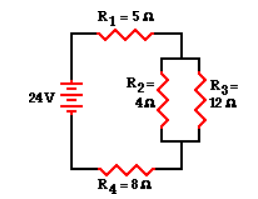
To simplify the circuit by replacing the two parallel resistors with a single resistor with an equivalent resistance. The equivalent resistance of a 4-Ω and 12-Ω resistor placed in parallel can be determined using the usual formula for equivalent resistance of parallel branches:
1 / Req = 1 / R1 + 1 / R2 + 1 / R3 ...
1 / Req = 1 / (4 Ω) + 1 / (12 Ω)
1 / Req = 0.333 Ω-1
Req = 1 / (0.333 Ω-1)
Req = 3.00 Ω
Based on this calculation, it can be said that the two branch resistors (R2 and R3) can be replaced by a single resistor with a resistance of 3 Ω. This 3 Ω resistor is in series with R1 and R4. Thus, the total resistance is
Rtot = R1 + 3 Ω + R4 = 5 Ω + 3 Ω + 8 Ω
Rtot = 16 Ω
Itot = ΔVtot / Rtot = (24 V) / (16 Ω)
Itot = 1.5 Amp
The 1.5 Amp current calculation represents the current at the battery location. Yet, resistors R1 and R4 are in series and the current in series-connected resistors is everywhere the same. Thus,
Itot = I1 = I4 = 1.5 Amp
At resonant frequency, XL = Xc
XL = 2 π f L and Xc = 1/ 2π f C
2 π f L = 1/ 2π f C
At resonance f = fr and on solving above equation we get,
1/ 2π  = fr Hz
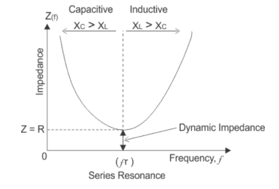
At resonance in series RLC circuit, two reactances become equal and cancel each other. So, in resonant series RLC circuit, the opposition to the flow of current is due to resistance only. At resonance, the total impedance of series RLC circuit is equal to resistance i.e Z = R, impedance has only real part but no imaginary part and this impedance at resonant frequency is called dynamic impedance and this dynamic impedance is always less than impedance of series RLC circuit.
References:
An Integrated Course In Electrical Engineering (3rd Edition) Book by J. B. Gupta
Basic Electrical Engineering Book by I.J. Nagrath
Objective Electrical Technology Book by Rohit Mehta and V.K. Mehta