Unit 3
Single Phase AC Circuits
Separately excited D.C. Machine:
When a separate D.C. Source is used to energize the field coils it is called as separately excited D.C. Machine. The connections showing the separately excited D.C. Machines are given in the figure.

Figure: (a) Separately excited D.C. Generator, (b) Separately excited D.C. Motor.
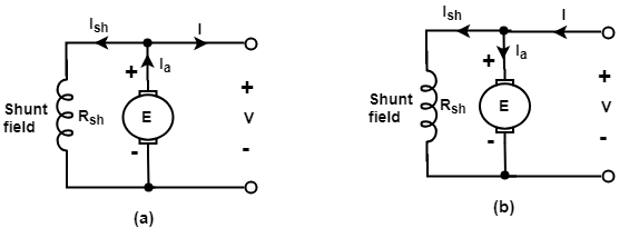
2. Shunt wound D.C. Machine:
Shunt wound D.C. Machines is the machine in which field coils are connected in parallel with the armature. Since the shunt field receives the full output voltage of a generator or the supply voltage of a motor, it is generally made of a large number of turns of fine wire carrying a small field current.
3. Series wound D.C. Machine:
Series wound D.C. Machines is the machine in which the field coils are connected in series with the armature. The series field winding carries the armature current, and the armature current is large, that is why series field winding consists of few turns of wire of large cross-sectional area.
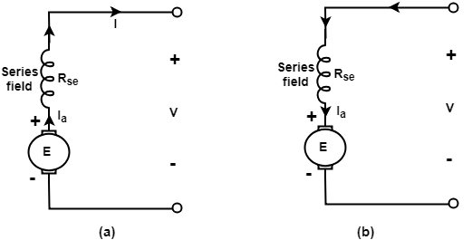
Figure: (a) D.C. Series generator (b) D.C. Series motor.
4. Compound wound D.C. Machine:
A Compound machine is a machine which has both shunt and series fields. Two windings are carried out by each pole of the machine. The series winding has few turns of large cross-sectional area, and the shunt windings have many turns of fine wire.
It can be connected in two ways. If the shunt field is connected in parallel with the armature alone, the machine is called the short-shunt compound machine and if the shunt field in parallel with both the armature and series field, the machine is called the long-shunt compound machine.

Figure: (a) Short-shunt compound D.C. Generator (b) Short-shunt compound D.C. Motor.
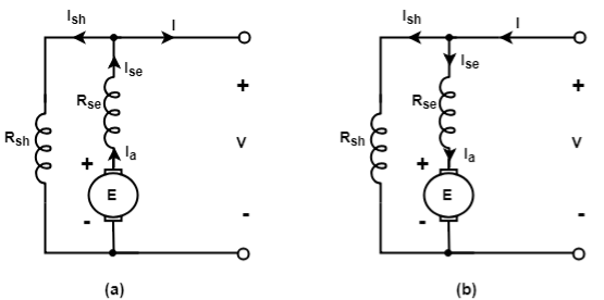
Figure: (a) Long-shunt D.C. Generator (b) Long-shunt D.C. Motor.
A DC generator or direct current generator is one kind of electrical machine, and the main function of this machine is to convert mechanical energy into DC (direct current) electricity. The energy alteration process uses the principle of energetically induced electromotive force.
The DC generator working principle is based on Faraday’s laws of electromagnetic induction.
When a conductor is located in an unstable magnetic field, an electromotive force gets induced within the conductor. The induced e.m.f magnitude can be measured from the equation of the electromotive force of a generator.
If the conductor is present with a closed lane, the current which is induced will flow in the lane.
In this generator, field coils will generate an electromagnetic field as well as the armature conductors are turned into the field. Therefore, an electromagnetically induced electromotive force (e.m.f) will be generated within the armature conductors. The path of induced current will be provided by Fleming’s right-hand rule.
The emf equation of dc generator according to Faraday’s Laws of Electromagnetic Induction is
Eg= PØZN/60 A
Where Φ is a flux or pole within Webber
Z is a total no.of armature conductor
P is a number of poles in a generator
A is a number of parallel lanes within the armature
N is the rotation of armature in r.p.m (revolutions per minute)
E is the induced e.m.f in any parallel lane within the armature
Eg is the generated e.m.f in any one of the parallel lanes
N/60 is the number of turns per second
Time for one turn will be dt = 60/N sec
Generators are classified based on how their fields are excited that is produced. There are three methods of excitation, and thus three main types of DC generators:
- Permanent Magnet DC Generators – Field coils excited by permanent magnets
- Separately Excited DC Generators – Field coils excited by some external source
- Self- Excited DC Generators – Field coils excited by the generator itself
Permanent Magnet DC Generator
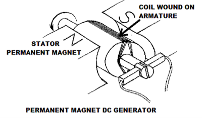
When the flux in the magnetic circuit is created through the use of permanent magnets, then it is known as a Permanent magnet DC generator.
It consists of an armature and one or several permanent magnets situated around the armature. This type of DC generator generates does not generate much power.
Separately Excited DC Generator
These are the generators whose field magnets are energized by some external DC source, such as a battery.
A circuit diagram of separately excited DC generator is shown in the figure below. The symbols below are:
- Ia = Armature current
- IL = Load current
- V = Terminal voltage
- Eg = Generated EMF (Electromagnetic Force)
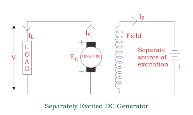
Voltage drop in the armature = Ia × Ra (R/sub>a is the armature resistance)
Let,
Ia = I L = I
Then,
Voltage drop across the load V = I Ra
Power generated is equal to Pg = Eg x I
And power delivered to the external load is equal to
P L = V x I
The DC motor or direct current motor works on that principal. This is known as motoring action.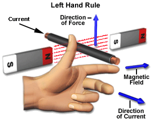
The direction of rotation of a this motor is given by Fleming left hand rule , which states that if the index finger, middle finger, and thumb of your left hand are extended mutually perpendicular to each other and if the index finger represents the direction of magnetic field, middle finger indicates the direction of current, then the thumb represents the direction in which force is experienced by the shaft of the DC motor.
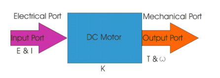
Here in a DC motor, the supply voltage E and current I is given to the electrical port or the input port and we derive the mechanical output i.e. torque T and speed ω from the mechanical port or output port.
T = K I and E = K w
The parameter K relates the input and output port variables of the direct current motor.
So from the picture above, the motor is just the opposite phenomena of a DC generator, and we can derive both motoring and generating operation from the same machine by simply reversing the ports.
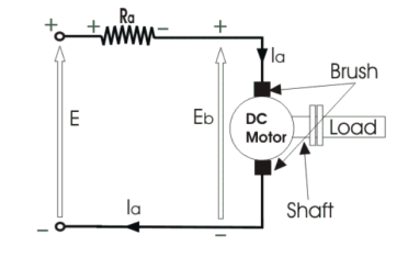
- The circle in the centre represents the direct current motor. On the circle, we draw the brushes. On the brushes, we connect the external terminals, through which we give the supply voltage.
- On the mechanical terminal, we have a shaft coming out from the centre of the armature, and the shaft couples to the mechanical load.
- On the supply terminals, we represent the armature resistance Ra in series.
Now, let the input voltage E, is applied across the brushes. Electric current which flows through the rotor armature via brushes, in presence of the magnetic field produces a torque Tg.
Due to this torque Tg the dc motor armature rotates. As the armature conductors are carrying currents and the armature rotates inside the stator magnetic field, it also produces an emf Eb in the manner very similar to that of a generator.
The generated Emf Eb is directed opposite to the supplied voltage and is known as the back Emf, as it counters the forward voltage.
The back emf like in case of a generator is represented by
Eb = P . ɸ . Z . N / 60. A ------------------------------(1)
Where, P = no of poles
φ = flux per pole
Z= No. Of conductors
A = No. Of parallel paths
and N is the speed of the DC Motor.
So, from the above equation, we can see Eb is proportional to speed ‘N.’ That is whenever a direct current motor rotates; it results in the generation of back Emf.
The rotor speed by ω in rad/sec. So Eb is proportional to ω.
So, when the application of load reduces the speed of the motor, Eb decreases. Thus the voltage difference between supply voltage and back emf increases that means E − Eb increases.
Due to this increased voltage difference, the armature current will increase and therefore torque and hence speed increases.
Thus, a DC Motor is capable of maintaining the same speed under variable load.
- It is seen in the generating action that when a conductor cuts the line of flux EMF gets induced in the conductor .In a DC motor after a motoring action a major start rotating and armature conductor cut the main flux so is there a generating action existing in a motor after Moni following actions
- There is induced EMF in the rotating armature conductors according to Faraday’s law of electromagnetic induction this induced EMF in the armature always act in the opposite direction to the supply voltage.
- This is according to the Lenz’s law which states that the direction of the induced EMF is always so as to oppose the cause producing it.
- In a DC motor electrical input that is the supply voltage is the cause for the armature current and the motoring action and hence this induced EMF oppose the supply voltage this EMF tries to set up a current through the our nature which is in the opposite direction to that which supply voltage is force in through the conductor.
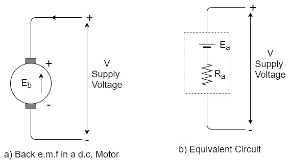
As this EMF always opposes the supply voltage it is called back EMF and denoted as  .Though it is denoted as
  basically it gets generated by the generating action which we have seen earlier in case of generators. So its magnitude can be determined by the EMF equation which is derived earlier.

Where all symbols carry the same meaning as seen earlier in case of generators
This EMF issued systematically in figure a so if v is supply voltage in volts &  is the value of the armature resistance the equivalent electric circuit can be shown in figure b
Torque equation of a D.C. Motor
The turning all twisting force about an exists is called torque.
Consider A wheel of radius R meters coated upon circumferential force F Newton as shown in figure (a)
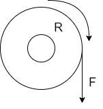
The wheel is rotating at a speed of N r.p.m. Then its angular speed is
W =  rad/sec
So work done in one revolution is
W=F×distance travelled in one revolution
= F×  Joules
P=power developed=
= (F×R) ×
P= T×W watts
Where T=torque in Nm and w = angular speed in rad/sec
Let  the gross torque developed by the armature of the motor. It is also called armature torque.
The gross mechanical power developed in the armature is  as seen from the power equation.
So if speed of the motor is N r.p.m then
Power in armature=armature torque×w i.e.  .
.
But  in a motor is given by


This is the torque equation of D.C. Motor
Types of torque in the motor
- The mechanical power developed in the armature is transmitted to the load through the shaft of the motor.
- It is impossible to transmit the entire power developed by the armature to the load. This is because while transmitting the power through the shaft, there is a power loss due to the friction windage and the iron loss.
- The torque required to overcome these losses is called lost torque, denoted as
 . These losses are called stray losses.
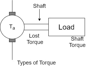
The torque which is available at the shaft for doing the useful work is known as Load torque or shaft torque denoted as

The shaft torque magnitude is always less than the armature torque (
The speed of the motor remains same all along the shaft say N r.p.m. Then the product of shaft torque  and the angular speed w rad/sec is called power available at the shaft i.e. net output of the motor. The maximum power a motor can deliver to the load safety is called output rating of a motor. Generally it is expressed in H.P. It is called H.P rotating of a motor.
Net o/p of motor=Pout= w
w
No load condition of the motor
On no load the load requirement is absent  =0
=0
This does not mean that motor is at half. The motor can rotate at No r.p.m on no load.
The motor draws on armature current of 

Where  is back e.m.f on no load proportional to speed
Now armature torque  for a motor is

As flux is present and armature current is is present, Hence  i.e. armature torque exist on no load.
 but on no load,
 =0
=0

So on no load motor produces a torque  which satisfies the friction, windage and iron losses of the motor.
Power developed ( =friction, windage and iron losses
Where  =back emf on no load
And  =armature current drawn on no load
This component of stray losses i.e.  practically assumed to be constant though the load on the motor is changed from 0 to the fall capacity of the motor.
1) A 4 pole D.C. Motor takes a 50A armature current. The armature has lab connected 480 conductors. The flux per Pole is 20 mWb . Calculate the gross torque developed by the armature of the motor.
- P=4, A=P=4, Z=480
 =20mWb=


 Nm
Nm
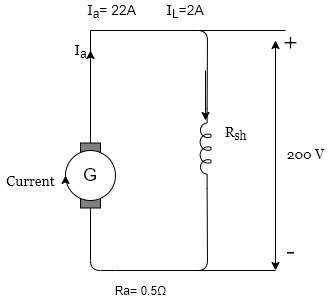
The field current in a D.C. Shunt machine is 2A and the line current is 20A at 200V. Calculate the
- The generated e.m.f when working as generator
- Talk in Nm when running at 1500 r.p.m as motor.
As a Generator

And line current=20A
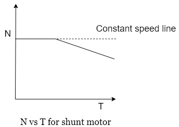
- Speed torque characteristics
These characteristics can be derived from above two characteristics
Motor characteristics
This graph is similar to speed armature current characteristics as torque is proportional to the armature current this curve shows that the speed almost remains constant torque changes from no load to full load conditions.
The gross mechanical power developed by motor is:
Pm = V Ia – I a 2 R a
Differentiating both sides with respect to Ia and equating the result to zero we get
Pm = V Ia – I a 2 R a
d Pm / d Ia = V – 2 Ia Ra =0
Ia Ra = V/2
As V = Eb + Ia Ra and Ia Ra = V/2
Eb = V/2
Thus, maximum efficiency of dc motor occurs when back EMF is equal to half the applied voltage.
The classification of speed control methods for a DC shunt motor are similar to those of a DC series motor. These two methods are:
- Armature Control Methods
- Field Control Methods
Armature Controlled DC Shunt Motor
Armature controlled DC shunt motor can be performed in two ways:
- Armature Resistance Control
- Armature Voltage Control
Armature Resistance Control
In armature resistance control a variable resistance is added to the armature circuit. Field is directly connected across the supply so flux is not changed due to variation of series resistance. This is applied for DC shunt motor. This method is used in printing press, cranes, hoists where speeds lower than rated is used for a short period only.
Armature Voltage Control
This method of speed control needs a variable source of voltage separated from the source supplying the field current. This method avoids disadvantages of poor speed regulation and low efficiency of armature-resistance control methods.
The basic adjustable armature voltage control method of speed d control is accomplished by means of an adjustable voltage generator is called Ward Leonard System. This method involves using a motor generator (M-G) set. This method is best suited for steel rolling mills, paper machines, elevators, mine hoists, etc. This method is known as Ward Leonard System.
Field Controlled DC Shunt Motor
By this method a DC Shunt motor’s speed is controlled through a field rheostat.
Field Rheostat Controlled DC Shunt Motor
In this method, speed variation is accomplished by means of a variable resistance inserted in series with the shunt field. An increase in controlling resistances reduces the field current with a reduction in flux and an increase in speed.
This method of speed control is independent of load on the motor. Power wasted in controlling resistance is very less as field current is a small value. This method of speed control is also used in DC compound motor.
TRANSFORMERS:
Transformer
A transformer is a static device that transfers electric power in one circuit to another circuit of the same frequency. It consists of primary and secondary windings. This transformer operates on the principle of mutual inductance.
When the primary of a transformer is connected to an AC supply, the current flows in the coil and the magnetic field build-up. This condition is known as mutual inductance and the flow of current is as per the Faraday’s Law of electromagnetic induction.
As the current increases from zero to its maximum value, the magnetic field strengthens and is given by dɸ/dt.This electromagnet forms the magnetic lines of force and expands outward from the coil forming a path of magnetic flux.
The turns of both windings get linked by this magnetic flux. The strength of a magnetic field generated in the core depends on the number of turns in the winding and the amount of current. The magnetic flux and current are directly proportional to each other.
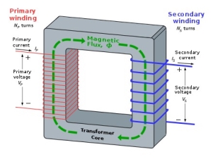
As the magnetic lines of flux flow around the core, it passes through the secondary winding, inducing voltage across it. The Faraday’s Law is used to determine the voltage induced across the secondary coil and it is given by:
N. dɸ/dt
Where,
‘N’ is the number of coil turns
The frequency is the same in primary and secondary windings.
Thus, we can say that the voltage induced is the same in both the windings as the same magnetic flux links both the coils together. Also, the total voltage induced is directly proportional to the number of turns in the coil.
Let us assume that the primary and secondary windings of the transformer have single turns on each. Assuming no losses, the current flows through the coil to produce magnetic flux and induce voltage of one volt across the secondary.
Due to AC supply, magnetic flux varies sinusoidally and it is given by,
ɸ = ɸmax Sin ωt
The relationship between the induced emf, E in the coil windings of N turns is given by,
E=N (d∅)/dt
E=N*ω*ɸmax cosωtφ
Emax=Nωɸmax
Erms=Nω/√2*ɸmax=2π/√2*f*N*ɸmax
Erms=4.44 fNɸmax
Where,
‘f’ is the frequency in Hertz, given by ω/2π.
‘N’ is the number of coil windings
‘ɸ’ is s the amount of flux in Webers
The above equation is the Transformer EMF Equation. For emf of a primary winding of a transformer E, N will be the number of primary turns (NP), while for the emf, E of a secondary winding of a transformer, the number of turns, N will be (NS).
Construction of Single- Phase Transformer
A simple single-phase transformer has each winding being wound cylindrically on a soft iron limb separately to provide a necessary magnetic circuit, which is commonly referred to as “transformer core”. It offers a path for the flow of the magnetic field to induce voltage between two windings.
Core-type Transformer
In this type of construction, only half of the windings are wound cylindrically around each leg of a transformer to enhance magnetic coupling as shown in the figure below. This type of construction ensures that magnetic lines of force flow across both the windings simultaneously. The main disadvantage of the core-type transformer is the leakage flux that occurs due to the flow of a small proportion of magnetic lines of force outside the core.
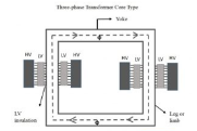
Core-type-transformer
Shell-type Transformer
In this type of transformer construction, the primary and secondary windings are positioned cylindrically on the center limb resulting in twice the cross-sectional area than the outer limbs. There are two closed magnetic paths in this type of construction and the outer limb has the magnetic flux ɸ/2 flowing. Shell type transformer overcomes leakage flux, reduces core losses and increases efficiency.
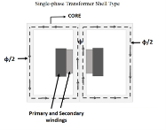
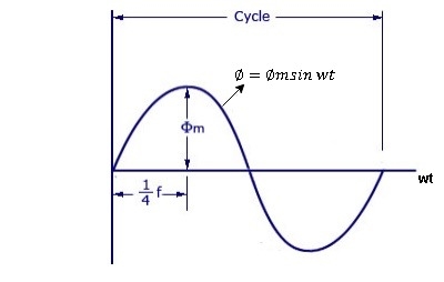
As primary winding excited by the a sinusoidal alternating voltage an alternating current flows in the winding producing an alternating varying flux Ø
Ø = Øm sin wt
As per Faradays Law of Electromagnetic Induction emf E1 is induced
E1 = N1 
E1 = N1  (Ø Sin wt)
= - N1 Øm w Cos wt
Sin (90-wt)
= - Sin (wt-90)
 E1 = N1 Øm w Sin (wt-90)
 w =
w = 
 E1 =
E1 =  N1 Ø m Sin (wt-90)
Max value of E1 = E max
Is when Sin (wt-90) =  1
1
E1 max =  N1 Ø m
Hence rms value of induced EMF in primary winding
E1 rms =  =
= 
 E1 = 4.44 F Ø m N1
 Similarly RMS value of induced EMF in secondary wdg Is
E2 = 4.44 F Ø m N2
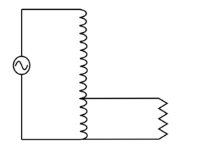
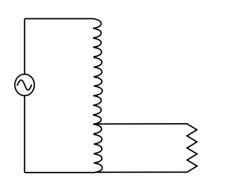
Auto-transformers definition: a single winding transformer with the primary and secondary windings magnetically and electrically connected.
There is only one winding in an auto-transformer. The common winding is the portion shared by the primary and secondary.
Step-down transformer:
Step-up transformer
THREE PHASE INTRODUCTION MOTOR:
Consider- 3Ф slip ring I.M
Cut section diagram:-
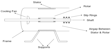
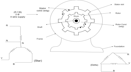
The induction motor has following important parts:-
- Stator :- it is the stationary part of induction motor and it is one of important part in induction motor.
- Rotor:- the rotor is the rotating part of induction motor which consists of rotor wdg.
- Stator winding:- this wdg. Is mounted on devastator and it generates the RMF i.e. rotating magnetic field.
- Rotor winding:- rotor winding is used to rotate the shaft of motor. This wdgis provided on rotor
- Frame :- it provides the mechanical support to the motor. It is the outer covering of motor. It protects the internal parts of motor from damage.
- Shaft:- shaft is used to connect to the load and four rotation.
- Slip rings and brushes:- slip rings are mounted on the shaft which is connected with brushes from which connection is given to the external resistant or rheostat
- Cooling fan:- this is provided for cooling purpose of motor and its internal parts.
Principle of operation of induction motor:
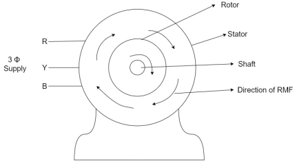
- When the 3Ф A.C supply is connected across the stator of induction motor, the current starts flowing through the stator wdg. i.ethe stator condition.
- Due to this current of flux (Ф) is established in the stator wdg. This flux (Ф) is alternating (changing) in nature. Thus this flux links with the rotor also, and a a Rotating Magnetic Field(RMF) is produced.
- This flux (Ф) induces emf in the rotor also. The RMF is produced in the air gap between stator and rotor.
- The rotor is rotating part which is till stationary, show the rotating magnetic field is cut by stationary rotor and an EMF is induced in the rotor winding. According to faraday's law of EMI the rotor EMF gives the rise to rotor current which opposes the main cause producing it according Lenz's law.
Two main types depending upon the rotor
- Squirrel cage induction motor (squirrel cage rotor)
- Slip ring induction motor(slip ring or wound rotor)
Induction motor are also available in 1Ф supply i.e.
1. Resistance split phase induction motor
2. Capacitor start induction motor
3. Capacitor start capacitor run induction motor
4. 1Ф induction motor i.e. A.C series motors
5. Shaded pole induction motor
Torque equation of induction motor:-
Torque produced in induction motor depends upon the following factors
1.The rotor power factors ( CosФ) under running condition
2.The rotor current under running condition
3. The part of RMF which induces EMF in rotor wdgi.e. flux (Ф)
We can mathematically say that,
 , As per DC (M) equation
But in case of induction motor
Suffix 1 -> used for stator/stator parts (qty)
Suffix 2-> used for rotor/rotor parts(qty)
Therefore,  ----(1)
 = flux that induces the EMF in rotor
 = rotor current under running condition
 = P.F of rotor
But, stator vtg
 also i.e
 ----(2)
Transformation ratio i.e. given by 
Therefore,
 and hence
 also
also
 at slip ’S’ is given by
And also  at slip ‘S’ is
  =S.
=S.
Hence  in equation can be replaced by
i.e.  U
U
 =
= ----(3)----(
 )
)
4 =
= ------(4)
Substract (3) and (4) into (1) equation we get,


 (N-m) , Torque equation of I.M.


At starting condition slip S=1
So, 
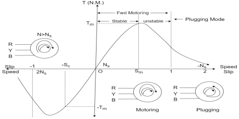
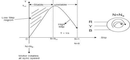
Torque slip region for stable regimen

S= small  -> Negligible


Unstable:-

 , neglect
 = Constant value
 =high slip region
 and vice versa

Various Torques ;
 at starting s=1 and 4N =0
 ----------slip is
  i.e..
i.e.. 
Total Torque

A Single-Phase Induction Motor consists of a single phase winding which is mounted on the stator of the motor and a cage winding placed on the rotor. A pulsating magnetic field is produced, when the stator winding of the single-phase induction motor shown below is energised by a single phase supply.
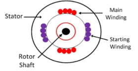
The word Pulsating means that the field builds up in one direction falls to zero and then builds up in the opposite direction. Under these conditions, the rotor of an induction motor does not rotate. Hence, a single phase induction motor is not self-starting. It requires some special starting means.
If the 1 phase stator winding is excited and the rotor of the motor is rotated by an auxiliary means and the starting device is then removed, the motor continues to rotate in the direction in which it is started.
The performance of the single phase induction motor is analysed by the two theories. One is known as the Double Revolving Field Theory, and the other is Cross Field Theory. Both the theories are similar and explain the reason for the production of torque when the rotor is rotating.
References:
An Integrated Course In Electrical Engineering (3rd Edition) Book by J. B. Gupta
Basic Electrical Engineering Book by I.J. Nagrath
Objective Electrical Technology Book by Rohit Mehta and V.K. Mehta