UNIT 4
Optoelectronic Devices and Displays
Photoconductive cell
These are two terminal device whose resistance is linear function of light intensity. The photoconductive materials used are cadmium sulphate and cadmium selenide. There is large change response of a cadmium sulphide in applications where the resistance of a cadmium selenide cell with changes in ambient temperature. But the resistance of cadmium sulphide remains relatively stable. The spectral response of a cadmium sulphide cell closely matches that of the human eye.
The ceramic substrate, photoconductive material, electrodes and a moisture resistant enclosure are mainly required.
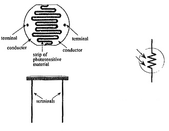
A long strip of light sensitive material is placed across a zigzag disc shaped base with protective sides. These cells are used for relay control. They are not suitable for analog applications as the temperature variation causes substantial variations in resistance for particular light intensity.
Photovoltaic cell
It is a semiconductor device which converts light into electrical energy. The working of this cell depends on photoelectric effect. The semiconductor material commonly used for this cell are silicon and selenium. The upper surface of cell is made of p-type material helping the light to entre easily. The metal rings are placed around p-type and n-type material which are positive and negative terminals of cell.
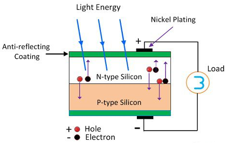
As semiconductor material is used so the light incident may be passed or reflected. When they absorb light the electrons are emitted. This is because of the small particle photon present in light. The electron on absorbing these photons gain energy and start moving. The particles move in only one direction due to the application of electric field. This action produces current.
Photodiode
The photodiode is a p-n junction semiconductor diode which is always operated in the reverse biased condition.
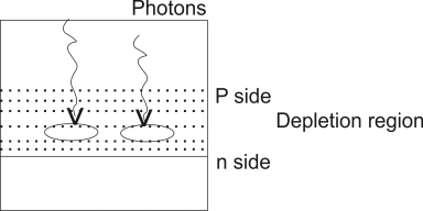
The light is always focused through a glass lens on the junction of the photodiode As the photodiode is reverse biased the depletion region is quite wide, penetrated on both side of the junction.
The photons incident on the depletion region will impact their energy to the Ions present in depletion region and generates e hole pairs.
The photons incident on the depletion region so the number of electron hole pairs will be generated depends on the intensity of light [number of photons] These and holes will be attracted towards the +ve& -ve terminals respectively of the photo current.
With increase in the light intensity more number of e hole pairs are generated and the photo current increases thus the photocurrent is proportional to the light intensity.
Phototransistor
It is a device which sense the light levels and alters the current flow between emitter and collector according to the level of light. The base is light sensitive. The construction is similar to transistor except the base. In this case base is not provided instead light is taken as input
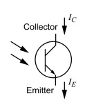
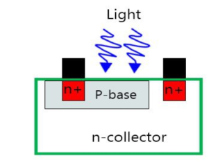
For transistor in open terminal base circuit collector base leakage current ICBO
IC= IB + (1+
 ) ICBO
Since IB=0
IC= (1+ ) ICBO
The collector current increases with the collector base region.
The base of phototransistor is used only for biasing. The light enters base region and produce electron hole pairs. The movement of electron in the presence of electric field produces current in base. The electrons from base are injected to the emitter. In case of NPN transistor, the collector is made positive concerning emitter, and in PNP, the collector is kept negative.
The 7-segment display shows seven segments. The seven segment allows us to display decimal numbers from 0 to 9. Below shown is the 7-segment LED with its truth table.

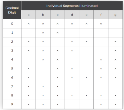
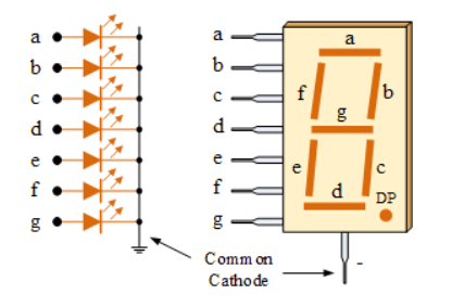
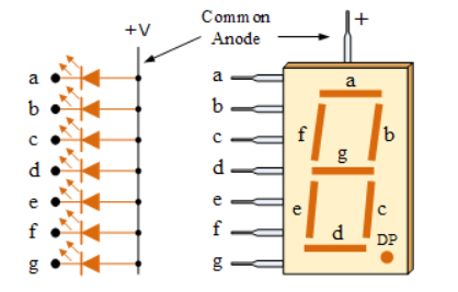
The segments can be light by forward biasing them properly in correct sequence and the other which are dark tighter make the proper desired number to be displayed. The displays common pin is generally used to identify which type of 7-segment display it is. As each LED has two connecting pins, one called the “Anode” and the other called the “Cathode”, there are therefore two types of LED 7-segment display called: Common Cathode (CC) and Common Anode (CA).
Common Cathode (CC): In this case all the cathode connections are connected to ground. The individual segment is turned ON by high logic.
Common Anode (CA): In this all the anode of LED are joined to logic 1. The individual segment is light up by applying 0 logic. These displays are generally used. For instance, to display the numerical digit 0, we will need to light up six of the LED segments corresponding to a, b, c, d, e and f.
An LED emits light when electrical energy is applied to it. For proper operation it is necessary to forward bias the LED.
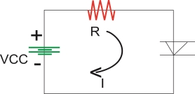
Construction of LED :-
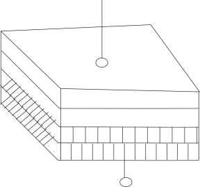
To make emission of light in one direction cup type construction is used for LED.
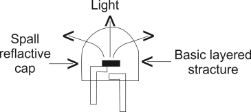
PRINCIPLE LED OPERATION
When the led is forward is forward biased the electrons in the n-region will cross the junction and recombine with the holes in the p- type material.
These free e- reside in the conduction band & hence at a higher energy level than the holes in the valence band
When recombination takes place this e- return peak to the valence band which is at a lower energy level than the conduction band.
While returning back the recombining e-give away the excess energy in the form of light . This process is called as electroluminescence. In this way an LED emits light.
Color of the Emitted Light
Material Use Color of Emitted Light
i)Gallium Arsenide (GOAS) In fared (IR)
Ii) GaASP(gallium arsenide Red or Yellow
Phosphide)
Iii) Gallium phosphide (GAP) Red or Green
Application
Used in 7 Segment Display
The liquid crystals are used to produce a visible image. Liquid crystal displays are super-thin technology display screens that are generally used in laptop computer screens, TVs, cell phones and portable video games. Light is projected from a lens on a layer of liquid crystal. This combination of colored light with the grayscale image of the crystal (formed as electric current flows through the crystal) forms the colored image. This image is then displayed on the screen.
When current is applied to liquid crystal molecule they untwist. This causes the angle of light which is passing through the molecule of the polarized glass and also cause a change in the angle of the top polarizing filter. They work on principle of blocking light. The electrode panel of indium-tin-oxide is kept on top and polarized glass with a polarized film on the bottom. This is enclosed by common electrode. Then completely covered by liquid crystal. When there is no current, the light passes through the front of the LCD it will be reflected by the mirror and bounced back. As the electrode is connected to a battery the current from it will cause the liquid crystals between the common-plane electrode and the electrode shaped like a rectangle to untwist. Thus, the light is blocked from passing through. That particular rectangular area appears blank.