UNIT 2
I.C. Engines
Two stroke. Four stroke engine:
In two stroke engine the working cycle is completed in two stroke of the piston or one revolution of crankshaft. This is achieved by carried out suction and compression in one stroke expansion and exhaust in the second stroke.
A two stroke engine has port instead of valves. Opening and closing of the port are controlled by the piston
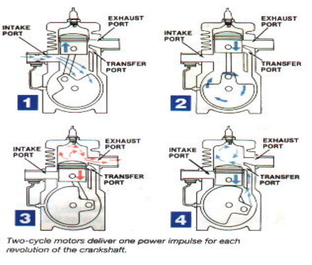
Following are the process in two stroke engine
1) Suction stroke: In this stroke piston while moving downward BDC (bottom dead centre) both the transfer port and exhaust port are open. The fresh fuel air mixture flows into the engine cylinder from crankcase.
2) Compression stroke: In this stroke, the piston while moving upwards, first cover the transfer port then exhausts port. After that fuel is compressed as the piston moves upwards. In this stage the inlet port opens and fresh air fuel mixture enters into crankcase.
3) Expansion stroke: During compression stroke the piston reached TDC (top dead centre) the charge is ignited with the help of spark plug .It suddenly increases the pressure and temperature of the product of combustion and volume remain constant. Due to rise in pressure the piston is pushed downwards with greater pressure .During the expansion some of the heat energy is produces and transform into mechanical work.
4) Exhaust stroke: In this stroke piston move downward and exhaust port is opened. The burned gases are exhaust from the engine cylinder through exhaust port into the atmosphere.
The two-stroke engines lighter, simpler and less expensive to manufacture. Two-stroke engines also have the potential to pack about twice the power into the same space because there are twice as many power strokes per revolution. The combination of light weight and twice the power gives two-stroke engines a great power-to-weight ratio compared to many four-stroke engine designs.
Four stroke engine
In four stroke engine the working cycle is completed in four stroke of the piston or two revolution of crankshaft. This is achieved by carried out suction in one stroke and compression in second stroke, expansion in third stroke and exhaust in the fourth stroke. They have inlet and exhaust valve. Suction and compression in one revolution of crankshaft, expansion and exhaust in second revolution of crankshaft.
Following are the process in four stroke engine;
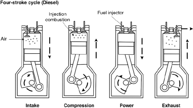
1) Suction stroke: In this stroke while piston moving downward BDC (bottom dead centre) inlet valve opens and pure air is sucked into the cylinder.
2) Compression stroke: In this stroke, the piston while moving from BDC to TDC, the inlet and outlet valve are closed. The compressed start as piston moves upwards. Which increase pressure and temperature .this complete one revolution of crankshaft
3) Expansion stroke: just before the piston reached the top dead centre fuel oil injected in the form of very fine spray into the cylinder . at this point temperature of the compressed air is sufficiently high to ignite the fuel which suddenly increase the pressure and temperature of combustion products. Due to increase in pressure the piston is pushed down with a great force.
4) Exhaust stroke: In this stroke exhaust valve open as piston move from BDC to TDC .This movement of the piston moves up and pushed out the burned gases to atmosphere from the engine cylinder
SI and CI engine
S.I Engine:
S I Stands for Spark Ignition. This is one kind of IC (Internal Combustion) engine.
There are four processes in engine.
- Intake or suction
- Compression
- Power or combustion
- Exhaust
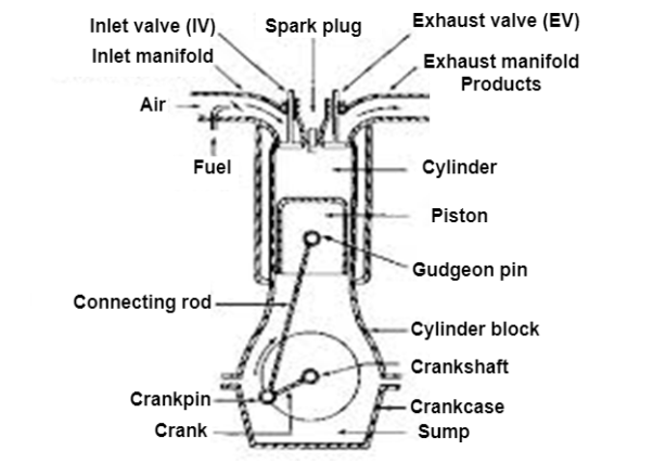
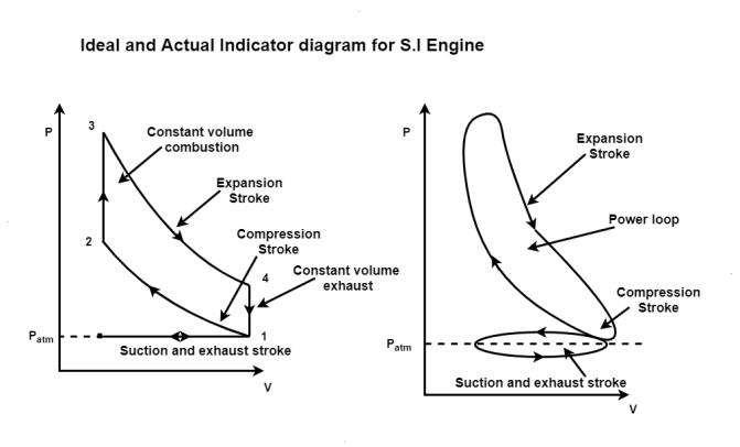
Process 0-1 (Suction stroke)
At the start of cycle the piston moves from TDC to BDC. The inlet valve (I.V.) is opened automatically by valve operating mechanism at the start of this process. Due to increase in volume inside the cylinder, a slight vacuum is created and, the fresh charge i.e. mixture of air and petrol prepared in Carburettor is sucked inside the cylinder through inlet valve. At the end of stroke, the piston reaches BDC position, total volume of cylinder is filled with fresh charge and inlet valve is closed. Theoretically, the charge is filled at constant pressure P1 and it occupies the total volume of cylinder V1.
Process 1-2 (Compression stroke)
During this stroke, both the valves remain closed and piston is moved from BDC to TDC by the force of crank. As the piston moves up, volume of cylinder shrinks and the fresh charge is compressed to a higher pressure P2 and volume V2 equal to clearance volume. Theoretically, this process is adiabatic compression process. Temperature of fresh charge is also raised in compression from T1 to T2.
Process 2-3 (heat addition or constant volume combustion)
This process is actually a constant volume heat addition process. At point 2, spark plug ignites and starts the combustion of already compressed, high temperature charge. Due to very favourable conditions of combustion, combustion of charge and heat release takes place in no time and pressure & temperature further shoots up to P3 and T3. Theoretically the volume remains constant from 2 to 3. So V2=V3=VC=Clearance Volume.
Process 3-4 (expansion or working stroke)
This is the process or stroke of piston in which positive work is obtained. The burnt gases at high pressure and high temperature at point 3 expand and push the piston again from TDC to BDC, thus doing work on the piston. This work is given to output shaft of engine through connecting rod and crank shaft. A small portion of it is stored in the heavy rotating flywheel mounted on crankshaft, which is used in movement of piston in three other idle stroke i.e. Suction, Compression and Exhaust. When piston reaches BDC, cylindrical total volume is filled with comparatively lower pressure and temperature burnt gases or smoke. At this point 4, the exhaust valve (EV) opens.
Process 4-1 (heat rejection or constant volume exhaust)
In this process, as soon as the exhaust valve is opened at point 4, the burnt gases start escaping to atmosphere and their pressure reduces to atmospheric pressure P1. Theoretically, this process happens in no time and escaping of exhaust gases take away some heat from the engine.
Process 1-0 (exhaust stroke)
This stroke is just opposite to suction stroke. Piston moves from BDC to TDC and pushes away or sweeps the remaining burnt gases out through E.V. As the piston reaches TDC most of burnt gases escape and E.V. Is closed. One cycle of the engine completes here. Simultaneously, the I.V. Opens and next cycle starts.
In this way, piston goes on moving or reciprocating from TDC to BDC and BDC to TDC with a high speed and engine produces power continuously by burning of petrol or gas etc. The power output and RPM of engine can be easily controlled by a throttling valve fitted in the passage of air intake or in the carburettor where fuel and air are mixed together in the right proportion In the exhaust phase, the piston goes upward and the burnt gases go away through the exhaust valve.
C.I Engine:
A diesel engine is called compression Ignition engine because here the conditions of combustion or ignition are achieved only by compression of air to a very high pressure.
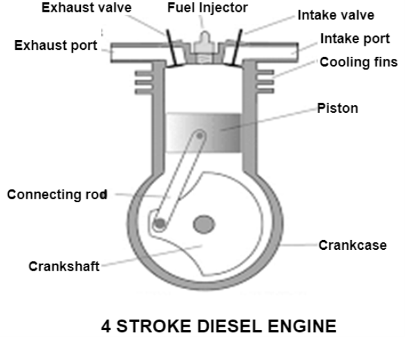
There is no spark plug to initiate the combustion, but in place of that a fuel injector is there, which injects and atomizes the fuel. Diesel at a very high pressure in very hot compressed air after compression stroke in engine Due to high pressure and temperature above the ignition temperature, fuel atomization, evaporation and self-ignition take place.
The rest of the working of Diesel Engine is same as that of Petrol or Gasoline Engine. Here also one complete cycle is comprised of all the processes of Diesel cycle along with suction of fresh air and exhaust of burnt gases. To carry out all these processes, here also normally 4 strokes of piston are required. So, it is called a 4-stroke Diesel Engine or C.I Engine.

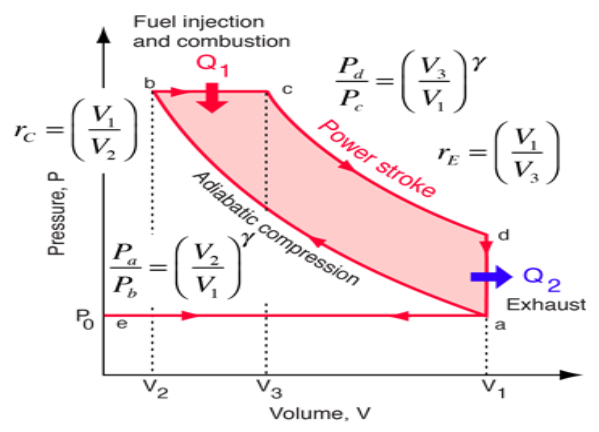
Process e-a (suction stroke)
At the start of cycle, the piston moves from TDC to BDC and inlet valve is opened at the start of process at point e. Due to increase in volume of cylinder by the movement of piston, the fresh air from atmosphere enters the cylinder and occupies all the space inside the cylinder until piston reaches BDC. At the point a, air filled in cylinder is at volume V1 and its pressure & temperature are theoretically same as that of outside atmosphere. Here inlet valve is closed and cylinder becomes a closed thermodynamic system.
Process a-b (compression stroke)
In this stroke, piston moves from BDC to TDC by the force of crank. As both valves are closed, the air sucked in previous stroke is compressed to the clearance volume. Here in Diesel engine the compression ratio rc which is the ratio of total volume V1 to clearance volume V2 is very high as compared to SI Engine. So, naturally the rise in pressure and temperature of air at the end of compression stroke is also more. The range of rc (compression ratio) in Diesel Engine is 15 to 22. Theoretically, the compression process is adiabatic & isentropic Compression.
Process b-c (heat addition or fuel injector)
This process is actually a constant pressure heat addition process or a mix of constant volume and constant pressure process as in case of high speed diesel engine. At the point b the fuel injector injects a fix quantity of fuel in very hot & compressed air compressed to the clearance volume. Due to that fuel spray ignites itself thus releasing of heat in the cylinder. As this heat addition process is slow, piston moves back to some distance from TDC to point c shown in fig and the volume increases which nullifies the effect of increase in pressure due to heat addition. Pressure remains constant theoretically upto point c, where the injector stops injection of fuel and so the addition of heat. Point c is also called cut-off point. A part of piston stroke from b to c takes place along with this process and the burning fuel plus air mixture expand and push the piston producing a positive work.
Process c-d (expansion stroke or power stroke)
Actually the complete expansion stroke is from point b to point d but a part of it is along the previous heat addition process b-c. After point c heat addition stops and the hot and high pressure burnt gases expand at the cost of their own internal energy and produce positive work by pushing the piston to BDC. This stroke is called working stroke as here piston moves the crankshaft and give mechanical energy. Major part of this energy is given to output shaft and a small portion is stored in heavy flywheel in the form of its rotational kinetic energy and used up during idle strokes of piston i.e. Suction, Compression & Exhaust.
Process d-a (heat rejection)
This process takes place at constant volume and heat is rejected directly by escaping of some of burnt gases due to pressure difference inside and outside the engine as soon as exhaust valve opens at point d i.e. just at the end of expansion or working stroke. Theoretically, piston remains at BDC and gases escape in no time, taking away some heat from the engine. Pressure inside the cylinder reduces to atmospheric pressure.
Process a-e (exhaust stroke)
In this process or stroke, piston is moved by crank from BDC to TDC. As the exhaust valve remains open during this stroke, piston displaces or sweeps out the burnt gases through it and only a small fraction of gases remain in the clearance volume finally. The piston reaches TDC and the cycle completes as the initial conditions are again reached. At this point, exhaust valve closes and inlet valve opens and next cycle starts.
In this way piston moves or reciprocates from TDC to BDC and again from BDC to TDC with a high speed and engine produces power continuously by burning of air and fuel mixture. The power output and RPM of engine here can be controlled by controlling the quantity of fuel injected only. There is no restriction on the quantity of air sucked by engine. There is a mechanical or electric control on the fuel injection depending on fuel injection system used. When more power is required more quantity of fuel is injected and when less power is required accordingly fuel supply is reduced. There is no control on the quantity of air so air sucked remains more or less same. In this way only the quality of combustible mixture changes in different conditions of loading and so Quality Governing is used in CI Engine.
OTTO CYCLE:
Otto cycle is a thermodynamic cycle upon which a spark ignition engine works. Spark Ignition (or SI) engine uses petrol (or Gasoline) as fuel. Otto cycle was invented by Nicolas Otto in 1876.
Spark ignition engine is a type of internal combustion engines.
Below are P-V and T-S Diagrams of the Otto Cycle.
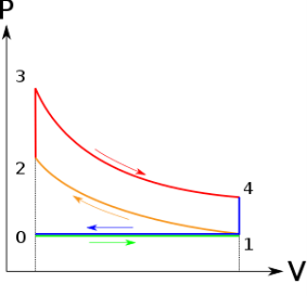
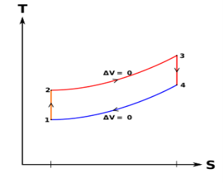
Otto Cycle is comprised of four processes (apart from the intake and exhaust process)
Process 1-2: This process comes after intake process. In case of SI engines, intake is a mixture of gasoline and air, also known as charge. In this process charge is compressed in isentropic manner. Temperature raised from T1 to T2 and volume decrease from V1 to V2.
Process 2-3: In this process the fuel gets blasted with the help of external spark (that is why the engine is known as spark ignition engine). This process is a constant volume heat addition process. Temperature raised from T2 to T3
.
Q2-3= CV(T3-T2)
Process 3-4: After the combustion process, the exhaust gases expend. This process is an isentropic expansion process. No heat is interchanged. The temperature fall from T3 to T4 and volume increase from V3 to V4.
Process 4-1: After the expansion process, exhaust valve opens. This results into sudden drop of pressure inside engine cylinder. This process is a constant volume heat rejection process.
Q4-1= CV(T4-T1)
Process 0-1 is the intake process and process 1-0 is the exhaust process.
Efficiency of the Otto Cycle is the ratio of work output to the heat input.
Work done or output = Heat supply-Heat rejected
Work output = [CV (T3-T2)] – [CV (T4-T1)]
Heat Input = CV (T3-T2)
Efficiency = Work done / Heat Input
After putting values of heat input and work output in the above formula, we get
η = [CV (T3-T2)] – [CV (T4-T1)] / CV (T3-T2)
η = 1 – [(T4-T1)/ (T3-T2)]
η = 1 – [T1 (T4 / T1 – 1 )/ T2 (T3/T2 - 1)]
r = compression ratio = V1 / V2 = V4 / V3
T2 = T1 (V1/V2) y-1
T2 = T1 (r) y-1 …..equation 1
T3/T4 = (V4 /V3)y-1
T3 = T4 (r) y-1 ……equation 2
From equation 1 and 2
T2 / T1 = T3/T4
Or T4 / T1 = T3 / T2
Put the value in this equation
η = 1 – [T1 (T4 / T1 – 1)/ T2 (T3/T2 - 1)]
We get
η = 1 – [T1 / T2]
Or η = 1 – 1 / (r )y-1
DIESEL CYCLE
Diesel cycle is a gas power cycle invented by Rudolph Diesel in the year 1897. It is widely used in diesel engines.
Diesel cycle is similar to Otto cycle except in the fact that it has one constant pressure process instead of a constant volume process (in Otto cycle).
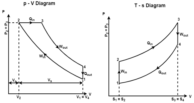
Diesel cycle can be understood well if you refer its p-V and T-s diagrams.
P-V and T-s Diagrams of Diesel Cycle:
|
|
|
|
|
|
|
|
Processes in Diesel Cycle:
Diesel cycle has four processes. They are:
- Process 1-2: Isentropic (Reversible adiabatic) Compression
- Process 2-3: Constant Pressure (Isobaric) Heat Addition
- Process 3-4: Isentropic Expansion
- Process 4-1: Constant Volume (Isochoric) Heat Rejection
Process 1-2: Isentropic Compression
In this process, the piston moves from Bottom Dead Centre (BDC) to Top Dead Centre (TDC) position. Air is compressed isentropically inside the cylinder. Pressure of air increases from p1 to p2, temperature increases from T1 to T2, and volume decreases from V1 to V2. Entropy remains constant (i.e., s1 = s2). Work is done on the system in this process (denoted by Win in the diagrams above).
Process 2-3: Constant Pressure Heat Addition
In this process, heat is added at constant pressure from an external heat source. Volume increases from V2 to V3, temperature increases from T2 to T3 and entropy increases from s2 to s3.
Heat added in process 2-3 is given by
Qin = mCP(T3 − T2) kJ ………… (i)
Where,
m → Mass of air in kg
Cp → Specific heat at constant pressure in kJ/kg K
T2 → Temperature at point 2 in K
T3 → Temperature at point 3 in K
Process 3-4: Isentropic Expansion
Here the compressed and heated air is expanded isentropically inside the cylinder. The piston is forced from TDC to BDC in the cylinder. Pressure of air decreases from p3 to p4, temperature decreases from T3 to T4, and volume increases from V3 to V4. Entropy remains constant (i.e., s3 = s4). Work is done by the system in this process (denoted by Wout in the p-V and T-s diagrams above).
Process 4-1: Constant Volume Heat Rejection
In this process, heat is rejected at constant volume (V4 = V1). Pressure decreases from P4 to P1, temperature decreases from T4 to T1 and entropy decreases from s4 to s1.
Heat rejected in process 4-1 is given by
Qout = mCv(T4 − T1) kJ ………… (ii)
Where,
m → Mass of air in kg
Cv → Specific heat at constant volume in kJ/kgK
T2 → Temperature at point 2 in K
T3 → Temperature at point 3 in K
Air-standard Efficiency of Diesel Cycle:
Air-standard efficiency (or thermal efficiency) of diesel cycle is given by:
ηTh= ηDiesel= Heat Added – Heat Rejected / HeatAdded×100%
ηDiesel=Qin−Qout / Qin×100%
From equations (i) and (ii)
ηDiesel= mCp(T3–T2)– mCV(T4–T1) / mCp (T3–T2)×100%
ηDiesel = (1−mCV (T4−T1) / mCp(T3−T2))×100%
ηDiesel = (1−CV (T4−T1)/ Cp(T3−T2))×100%
ηDiesel = (1−1 / γ (T4−T1) / (T3−T2))×100% (Since Cp / CV= γ
CV / Cp=1/γ
Duel cycle:
The combustion process in a spark ignition engine does not occur exactly at constant volume, nor does the combustion process in an actual compression ignition engine occur exactly at constant pressure, therefore another idealized cycle known as Dual cycle has been developed that more closely approximate the actual spark-ignition and compression-ignition engines. The p-v and T-s diagrams of Dual cycle are shown in Fig. 45.1. In this cycle, part of heat addition occurs at constant volume while the rest is at constant pressure. The dual cycle is also called mixed or limited pressure cycle.
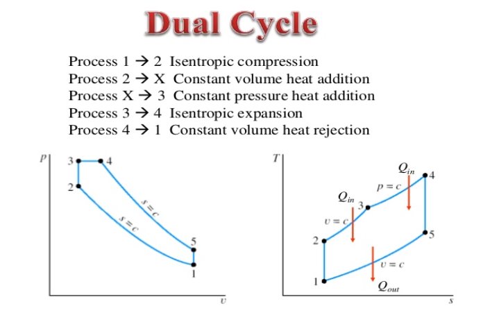
In a dual cycle, the system executing the cycle undergoes a series of five processes: two isentropic (reversible adiabatic) processes alternated with two isochoric process and one isobaric process:
Dual cycle – PV Diagram
Isentropic compression (compression stroke) – The gas is compressed adiabatically from state 1 to state 2, as the piston moves from intake valve closing point (1) to top dead centre. The surroundings do work on the gas, increasing its internal energy (temperature) and compressing it. On the other hand the entropy remains unchanged. The changes in volumes and its ratio (V1 / V2) are known as the compression ratio. The compression ratio is smaller than the expansion ratio.
Isochoric compression (ignition phase) – In this phase (between state 2 and state 3) there is a constant-volume (the piston is at rest ) heat transfer to the air from an external source while the piston is at rest at top dead center. This process is similar to the isochoric process in the Otto cycle. It is intended to represent the ignition of the fuel–air mixture injected into the chamber and the subsequent rapid burning. The pressure rises and the ratio (P3 / P2) is known as the “explosion ratio”.
Isobaric expansion (power stroke) – In this phase (between state 3 and state 4) there is a constant-pressure (idealized model) heat transfer to the air from an external source (combustion of the fuel) while the piston is moving toward the V4. During the constant pressure process, energy enters the system as heat Qadd, and a part of work is done by moving piston.
Isentropic expansion (power stroke) – The gas expands adiabatically from state 4 to state 5, as the piston moves from V3 to bottom dead center. The gas does work on the surroundings (piston) and loses an amount of internal energy equal to the work that leaves the system. Again the entropy remains unchanged.
Isochoric decompression (exhaust stroke) – In this phase the cycle completes by a constant-volume process in which heat is rejected from the air while the piston is at bottom dead center. The working gas pressure drops instantaneously from point 5 to point 1. The exhaust valve opens at point 5. The exhaust stroke is directly after this decompression. As the piston moves from bottom dead center (point 1) to top dead center (point 0) with the exhaust valve opened, the gaseous mixture is vented to the atmosphere and the process starts anew.
During the Dual cycle, work is done on the gas by the piston between states 1 and 2 (isentropic compression). Work is done by the gas on the piston between stages 2 and 3 (isobaric heat addition) and between stages 2 and 3 (isentropic expansion). The difference between the work done by the gas and the work done on the gas is the network produced by the cycle and it corresponds to the area enclosed by the cycle curve. The work produced by the cycle times the rate of the cycle (cycles per second) is equal to the power produced by the Diesel engine.
Thermal Efficiency for Dual Cycle
In general the thermal efficiency, ηth, of any heat engine is defined as the ratio of the work it does, W, to the heat input at the high temperature, QH.

The thermal efficiency, ηth, represents the fraction of heat, QH, that is converted to work. Since energy is conserved according to the first law of thermodynamics and energy cannot be be converted to work completely, the heat input, QH, must equal the work done, W, plus the heat that must be dissipated as waste heat QC into the environment. Therefore we can rewrite the formula for thermal efficiency as:

Therefore the heat added and rejected is given by:
Qadd-1 = mcv (T3 – T2)
Qadd-2 = mcp (T4 – T3)
Qout = mcv (T5 – T1)
Therefore the thermal efficiency for a dual cycle is:

Question The following data was recorded during testing of a TWO STROKE gas engine:
Diameter of the piston d= 150 mm
Stroke length L= 180 mm
Clearance volume Vc = 0.89 litre
RPM of the engine N = 300
Indicated mean effective pressure pm= 6.1 bars
Gas consumption m. = 6.1 m3/h
Calorific value of the gas (fuel) CF = 17000 kJ/m3
Determine the followings:
a) Air Standard Efficiency
b) Indicated power (IHP)developed by the engine
c) Indicated thermal efficiency of the engine
SOLUTION
Swept volume Vs = πd2L/4 = π(0.150)2 x 180/4 = 0.00318 m3
Clearance volume Vc= 0.00089 m3
Total volume = Swept volume + clearance volume
= 0.00318 + 0.00089 = 0.00407 m3
Compression ratio γ = Total volume/Clearance volume
= 0.00407/0.00089 = 4.573
a) Air standard Efficiency
η = 1 –1/(r)γ—1 = 1—1/(4.573)1.4—1
= 0.456 = 45.6 %
b) Indicated power IHP = 100 pLAN/60
When p is in bars
= 100 x 6.1x 0.180 x [π (0.150)2 /4] x 300 / 60
= 9700 W
(c ) Indicated Thermal Efficiency
ηit = Indicated power in (kJ/s)/Heat supplied in (kJ/s)
= (9700/1000)/ (6.1 x 17000/3600)
= 0.3367 = 33.67 %
Question
A FOUR STROKE petrol engine have given data below
Air fuel ratio 15.5: 1
Calorific value of fuel 16000 kJ/kg
Air Standard Efficiency: 53%
Mechanical Efficiency: 80 %
Indicated Thermal Efficiency: 37 %
Volumetric Efficiency: 80 %
Stroke/bore ratio: 1.25
Suction pressure: 1 bar
Suction Temperature: 270C
RPM: 2000
Brake Power: 72 kW
Calculate the followings:
a) Brake specific fuel consumption
b) Bore and stroke
SOLUTION
Find compression ratio from air standard efficiency
η = 1 –1/(r) γ—1
0.53 = 1 –1/(r) 1.4—1
r = 6.6
IHP = BP/Mechanical efficiency = 72/0.80
= 90 kW
ηit =IHP/(Specific Fuel Consumptions x Cal value)
0.37 = 90/sfc x 16000
Sfc is specific fuel consumption
Sfc = 0.0152 kg/s
a) Brake specific fuel consumption
Brake sfc = sfc IHP/BP
= 0.0152/72
=0.00021 kg/s /kW
Brake sfc = 0.7601 kg/kWh
b) Bore and stroke
Bore and stroke of the engine
Mass of air fuel mixture/kg of fuel = 15.5 +1 = 16.5
Mass of fuel supplied to the engine = 0.0152 x 16.5 = 0.2508
Volume of air fuel mixture = mRT/p
=0.2508 x 287 × 300/ (1×10⁵)
V = 0.2159 m3/s
Swept volume = volume of mixture supplied/vol efficiency
Vs = 0.2159/0.80= 0.2699
Vs = (πd2L/4) n x (rpm/2) /60
Where n is the number of cylinders
= (πd2 x 1.25 d/4)n rpm/120
d= 0.152 m= 152 mm
L = 190 mm
Question) In an air standard Otto cycle, the compression ratio is 7 and the compression begins at 35oC and 0.1 MPa. The maximum temperature of the cycle is 1100oC. Find
(a) The temperature and the pressure at various points in the cycle,
(b) The heat supplied per kg of air,
(c) Work done per kg of air,
(d) The cycle efficiency and
(e) The MEP of the cycle
Answer Given T1=35oC=308 K
P1=0.1 Mpa
T3=1100oC=1373 K
r=v1/v2=7
(a) the temperature and the pressure at various points in the cycle,
We know that P2/P1 = (V1 /V2)y = 71.4
Hence, P2=1524 k Pa
We also know that T2 / T1 = (V1/V2) y-1 = 71.4
We get T2=670.8 K
For process, 2-3, P2V2 / T2 = P3V3 / T3
P3 = T3 P2 /T2
P3= 1373 X 1524 / 670.8
P3 = 3119.34 kPa
Process 3-4 is isentropic T3/T4 = (V4 /V3) y-1 = 71.4-1
T4 = 1372 / 2.178
T4 =630.39 K
(b) The heat supplied per kg of air,
Heat input = Qin= cv(T3-T2)
=0.718(1373–670.8)
= 504.18 kJ/kg
Heat rejected = Q out= cv (T4-T1)
=0.718(630.34–308)
=231.44 kJ/kg
(c) work done per kg of air,
The network output Wnet=Qin-Qout
The net work output, Wnet=Qin-Qout
=272.74 kJ/kg
(d) the cycle efficiency
Thermal efficiency, ηth otto=Wnet/Qin
=0.54 =54 %
Otto cycle thermal efficiency, ηth otto =1-1/rγ-1
= 1-1/70.4 = 0.54 or 54 %
v1=RT1/P1 =0.287 x 308 / 100=0.844 m3/kg
(e) The MEP of the cycle
MEP = Wnet/(v1–v2) = 272.74/v1 (1-1/r)
=272.74/0.844 (1-1/7)
=360 kPa