UNIT 3
Simple Lifting Machines
A machine is a device which is capable of doing useful work.
Machines which are used to lift the loads are known as lifting machines
Machines may be of following two types
- Simple machines
- Compound machines
SIMPLE MACHINES:-
A machine having only one point at which effort can be applied & one point for load is called simple machines
Example:- pulley, lever, screw jock are examples of simple machines
COMPOUND MACHINES:-
A machine which has more than one point for he application of load & for effort is called compound machine
For example:- lathe machine, milling machine, printing machine etc.
DEFINITIONS:-
- Effort:- it is the force required by a machine to lift the load it is denoted by P
- Velocity ratio:- it is the ration of distance moved by the effort to the distance moved by the load
V.R. (velocity ratio)
- Mechanical advantage:- it is the ratio of the load lifted to the effort applied it is denoted by M.A.
- Efficiency of a machine:- it is the ratio of the output of the machine to the input of the machine it is denoted by N
Or
Efficiency of a machine is also defined as the ratio of mechanical advantage & velocity ratio
- Ideal machine:- if efficiency 100% is said to be ideal m/c for died m/c
n = 100%
i.e. output = input Or M.A. = V.R
i) Velocity ratio:
It is defined as the ration of distance travelled by the effort (P) to the distance travelled by the load (W)
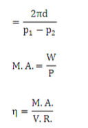
V.R. = Distance travelled by the effort / Distance travelled by the load
Velocity ratio will be always more than one and for a given machine, it remains constant.
Ii) Mechanical Advantage:
It is defined as the ratio of load to be lifted to the effort applied.
M.A = Load (w) / Efforts (p)
Iii) Efficiency.
If a machine overcomes a load ‘L’ and the distance travelled by the load is ‘Ld’, the work done by the load is L × Ld. It is also called output work or useful work. Therefore,
Output work = L × Ld
Likewise, the effort applied to overcome the load is E and the distance covered by effort is Ed, the work done by effort is E × Ed. It is also called input work. Therefore,
Input work = E × Ed
The efficiency of a simple machine is defined as the ratio of useful work done by a machine (output work) to the total work put into the machine (input work).
For ideal or perfect machine, work output is equal to the work input. Ideal machines are those imaginary machines which are frictionless. In practice, the work output of a machine is always less than work input due to the effect of friction. If the frictional force in the machine increases the efficiency decreases because machines are frictionless in practice, the efficiency of a machine can never be 100%.
Iv) Laws of machines
The relation b/w the effort required in a machine and the load is called the law of a machine.
We plot a graph between load & effort, we get a straight line. For an ideal machine the straight line will pall through origin. For an actual machine straight line will have an intercept C’
C is the amount of effort required by the m/c to overcome the friction.
For actual m/c P= mw + c
Where m=slope of line and is equal to c.o.f. (µ)
W= load lifted
P= effort
For ideal m/c P = mw
v) Reversibility of machine
The machine which is capable of doing work in the reverse direction, after the effort is removed the machine is said to be reversible machine
For example- water bucket falls back in the well on the removal of effort
For Reversible m/c n > 50%
Vi Differential wheel and axle
Differential axle and wheel is a further modification and improvement over the simple axle and wheel.
It consists of a load axle made up of bigger axle of diameter d1 and smaller axle of diameter d2 rigidly connected to each other and an effort wheel of diameter „D‟. Since, the load axle is made up of two axles of different diameters; it is called as a differential axle. Differential axle and effort wheel are mounted on the same shaft which is supported on ball bearings as shown in the figure.
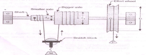
A string is wound round the effort wheel so as to apply the effort „P‟. Another string is wound round the bigger axle further passing over the pulley carrying the load „W‟ attached to the snatch block. The same string is further wound round the smaller axle in the opposite direction to that of bigger axle. The winding of string on effort wheel and smaller axle is done in the same direction; the string unwinds from the effort wheel & smaller axle and winds over the bigger axle simultaneously, when the effort „P‟ is applied.
When effort wheel complete one revolution, the differential axle also completes one revolution.
Distance travelled by the effort = πD
Length of the string wound over the bigger axle = πd1
Length of the string unwound over the smaller axle = πd2
Total winding over the bigger axle = πd1 - πd2 = π(d1 – d2)
But, the load „W‟ is lifted through half of the total winding because snatch block with a movable pulley supports the load
Distance travel by the load = ½ (total winding) = ½ π(d1-d2) = π/2(d1-d2)
We know that
V.R. = Distance travelled by the effort / Distance travelled by the load
= Πd / (π/2) x (d1-d2)
Where, D = Diameter of effort wheel, d1 = diameter of bigger axle, d2 = diameter of smaller axle.
If radius of effort wheel, bigger axle and smaller axle are given then,
V.R = 2R / R1- R2
Where, R = Diameter of effort wheel, R1 = diameter of bigger axle, R2 = diameter of smaller axle.
i) Differential pulley block
A differential pulley, also called "Weston differential pulley", sometimes "chain hoist" or colloquially "chain fall", is used to manually lift very heavy objects like car engines. It is operated by pulling upon the slack section of a continuous chain that wraps around pulleys; the relative size of two connected pulleys determines the maximum weight that can be lifted by hand. If the pulley radii are close enough the load will remain in place (and not lower under the force of gravity) until the chain is pulled.
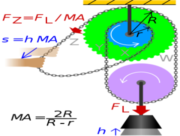
The two sections of chain carrying the single pulley exert opposing and unequal torques on the connected pulleys, such that only the difference of these torques has to be compensated manually by pulling the loose part of the chain; this leads to a mechanical advantage: the force needed to lift a load is only a fraction of the load's weight.
At the same time, the distance the load is lifted is smaller than the length of chain pulled by the same factor; this factor (the mechanical advantage MA) depends on the relative difference of the radii r and R of the connected pulleys:

The effect on the forces and distances (see figure) is quantitatively:

The difference in radii can be made very small, making the mechanical advantage of this pulley system very large. In the extreme case of zero difference in radii, MA becomes infinite, thus no force (besides friction) is needed to move the chain, but moving the chain will no longer lift the load.
Ii) Single, double and triple start worm and worm wheel
Worm gears are constructed of a worm and a gear (sometimes referred to as a worm wheel), with non-parallel, non-intersecting shafts oriented 90 degrees to each other. The worm is analogous to a screw with a V-type thread, and the gear is analogous to a spur gear. The worm is typically the driving component, with the worm’s thread advancing the teeth of the gear.
Like a ball screw, the worm in a worm gear may have a single start or multiple starts – meaning that there are multiple threads, or helicies, on the worm. For a single-start worm, each full turn (360 degrees) of the worm advances the gear by one tooth. So a gear with 24 teeth will provide a gear reduction of 24:1. For a multi-start worm, the gear reduction equals the number of teeth on the gear, divided by the number of starts on the worm. (This is different from most other types of gears, where the gear reduction is a function of the diameters of the two components.)
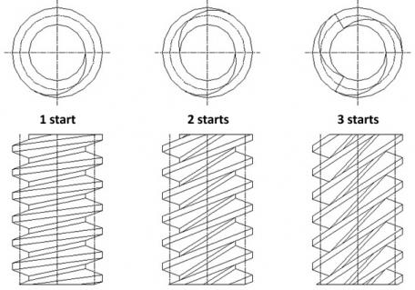
The worm in a worm gear assembly can have one start (thread) or multiple starts..
The meshing of the worm and the gear is a mixture of sliding and rolling actions, but sliding contact dominates at high reduction ratios. This sliding action causes friction and heat, which limits the efficiency of worm gears to 30 to 50 percent. In order to minimize friction (and therefore, heat), the worm and gear are made of dissimilar metals – for example, the worm may be made of hardened steel and the gear made of bronze or aluminium.
Although the sliding contact reduces efficiency, it provides very quiet operation. (The use of dissimilar metals for the worm and gear also contributes to quiet operation.) This makes worm gears suitable for use where noise should be minimized, such as in elevators. In addition, the use of a softer material for the gear means that it can absorb shock loads, like those experienced in heavy equipment or crushing machines.
The primary benefit of worm gears is their ability to provide high reduction ratios and correspondingly high torque multiplication. They can also be used as speed reducers in low- to medium-speed applications. And, because their reduction ratio is based on the number of gear teeth alone, they are more compact than other types of gears. Like fine-pitch lead screws, worm gears are typically self-locking, which makes them ideal for hoisting and lifting applications.
A Screw-jack is a device used for lifting heavy weights or loads with the help of a small effort applied at its handle. The followings are two types of screw-jack:
(a) Simple screw-jack, and
(b) Differential screw-jack.
a) Simple Screw-Jack. Fig.1 shows the simple screw jack, which consist of a nut, a screw the square threads and a handle fitted to the head of the screw. The nut also forms the body of the jack.
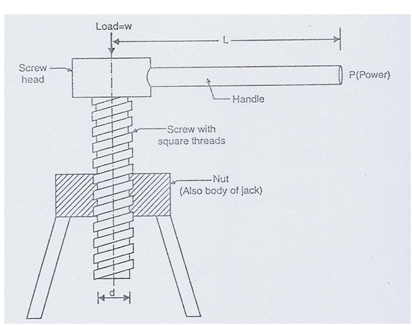
Fig. 1. Simple screw-jack
The load to be lifted is placed on the head of the screw. At the end of the handle, fitted to the screw head, an effort P is applied in the horizontal direction to lift the load W. The screw-jack works on the same principle on which an inclined plane works.
Let W = Weight placed on the screw head,
P = Effort applied at the end of the handle,
L = Length of the handle,
p = Pitch of the screw,
d = Mean diameter of the screw,
α = Angle of the screw or helix angle,
Φ = Angle of friction,
µ = Co-efficient of friction between the screw and nut = tan Φ
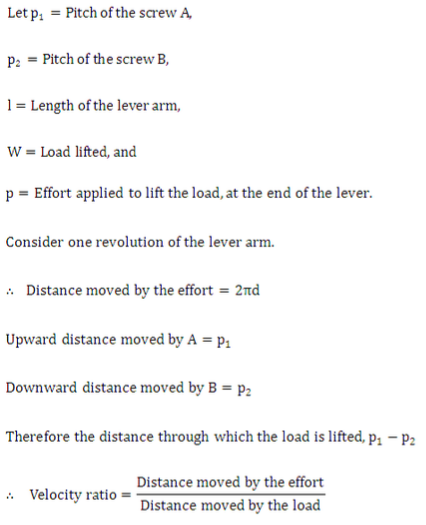
When the handle is rotated through one complete turn, the screw is also rotated through one turn. Then the load is lifted by a height p (pitch of screw).
b) Differential Screw-Jack. Fig. 2 shows a differential screw-jack. The principle, on which this machine works, is the same as that of any other differential machine, i.e., an action of one part of the machine is subtracted from the action of another part.
The differential screw is in two parts, A and B. Part A is threaded both on inside and outside; whereas part B is threaded on the outside only. The external threads of A gear with the threads of the nut C, which form the body of the differential screw-jack. The internal threads of A gear with the threads of the nut C, which form the body of the differential screw-jack. The internal threads of A gear with the external threads of the screw B. Thus part A behaves as a screw for the nut C and as a nut for the screw B.
The screw B does not rotate, but moves in the vertical direction only, and carries the load. When the effort is applied at the lever, the screw A rises up and simultaneously the screw B goes down. Thus the net life of the load is algebraic sum of the motions of the screw A and screw B.
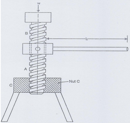
Fig 2
