UNIT 4
Basics of Power Transmission
BELT DRIVES:
The belt drive is used to transmit power from one shaft to another by means of pulleys which rotate at the same speed or at different speed.
I) open and cross belt drive
- Open Belt Drive:
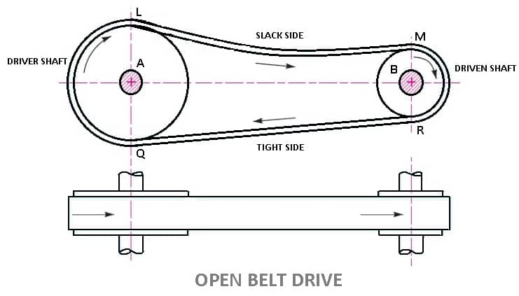
- In these types of belt drive, the belt is employing when the two parallel shafts have to rotate in the same direction.
- When the shafts are far apart, the lower side of the belt should be the tight side and the upper side must be the slack side.
- This is because, when the upper side becomes the slack side, it will sag due to its own weight and thus increase the arc of contact.
- In open belt drive, belt proceeds from top of one pulley to the top of other pulley without crossing.
- Contact angle (or wrap angle) between the belt and pulley is comparatively small (always below 180º in smaller pulley).
LENGTH OF OPEN BELT DRIVE FORMULA:
= π (r1 + r2) + 2x + (r1 – r2)2 /x ……………. (In terms of pulley radii)
= π/2 (d1 + d2) + 2x + (d1 – d2)2/ 4x ……….… (In terms of pulley diameters)
2. Cross Belt Drive
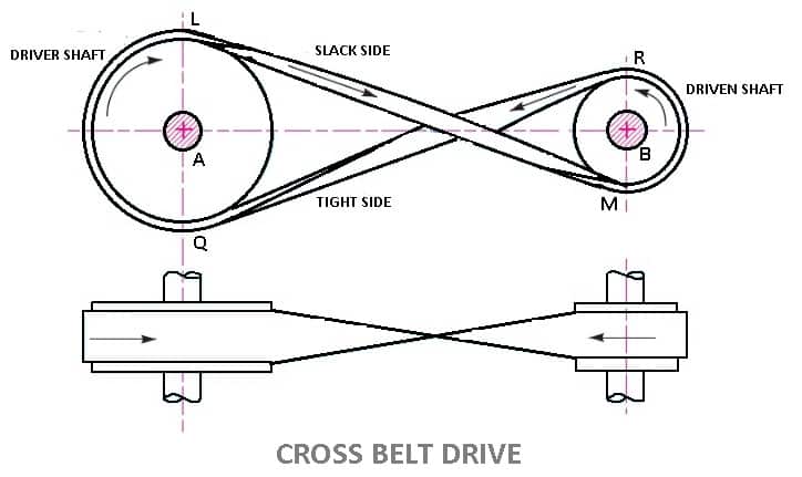
- In this types of belt drives, the belt is employing when two parallel shafts have to rotate in the opposite direction. At the junction where the belts cross, it rubs against itself and wears off.
- To avoid excessive wear, the shafts must be placed at a maximum distance from each other and operated at very low speeds.
- Contact angle between the belt and pulley is comparatively large (always above 180º in smaller pulley).
- In crossed belt drive, belt proceeds from top of one pulley to the bottom of other pulley and thus crosses itself.
- Here belt bends in two different planes in every rotation during its operation
- Cross belt drive can be advantageously applied for horizontal, inclined and vertical positions of driving and driven shafts.
- It can transmit more power as wrap angle is more.
LENGTH OF CROSS BELT DRIVE
= π (r1+r2) + 2x + (r1+r2)2 /x …………… (In terms of pulley radii)
= π/2(d1+d2) +2x + (d1 + d2)2/ 4x …………(in terms of pulley diameters)
Material of belts:
The Materials used for belts and ropes must be strong, flexible, and durable. It must have high coefficient of friction: like
1- Leather belts
2- Cotton belts
3- Rubber belts
4- Balata belts
1. Leather belts :
The leather may be oak tanned or mineral salt tanned. Example chrome tanned. When the thickness of the belt required is more then, two or more strips are cemented together. Leather belts require periodic cleaning.
2. Cotton belts or Fabric belts :
Fabric belts are made by folding canvas or cotton ducks in layers and stitching together. The fabric belts are cheaper and best suited in warm climates, damp atmospheres. These are mostly used in Farm machinery, belt conveyor etc.
3. Rubber belts :
Rubber belts are made of Fabric with rubber layer. Rubber belts are used in sawmills, paper mills, etc.
4. Balata Belts:
Balata belts are similar to rubber belts except that balata gum is used in place of rubber. Balata belts are acid proof and water proof and it is not effected by animal oils or alkalies. The balata belts should not be at temperatures above 40° C because at this temperature the balata begins to soften and becomes sticky. The strength of balata belts is 25 percent higher than rubber belts.
Type of belts:
Different types of belt are as follows
- Flat Belt
- V – Belt
- Circular Belt

1. Flat Belt :
Flat belt has a rectangular cross section. Flat belts are capable of transmitting power over long distance between pulley centres. The efficiency of this drive is around 98 % and produces less noise.
This belt is mostly used in factories and workshops, where a moderate amount of power is to be transmitted, from one pulley to another when two pulleys are not more than 8 metres apart.
Flat belts drives are of following types:
- Open belt drive.
- Cross belt drive.
- Stepped or cone pulley or speed cone drive.
- Fast and loose pulleys.
- Jockey pulley drive or belt drive with idler pulley
- Compound Belt Drive System
2. V – Belt:
V-Belts also used with grooved pulleys, V-belts are trapezoidal in cross section. V-belts permit large speed ratios and can transmit higher power. Multiple drives are possible.
This belt is mostly used in factories and workshops, where a moderate amount of power is to be transmitted, from one pulley to another when two pulleys are very near to each other.
3. Circular Belt or Round Belt :
Circular Belt or Round belt has a circular cross section and is used with grooved pulleys, This belt is mostly used in factories and workshops, where a great amount of power is to be transmitted, from one pulley to another when two pulleys are more than 8 metres apart.
Length of belt of open and cross drive:
Length of Open belts drive:
We have discussed that in an open belt drive, both the pulleys rotate in the same direction as shown in Fig. 1.
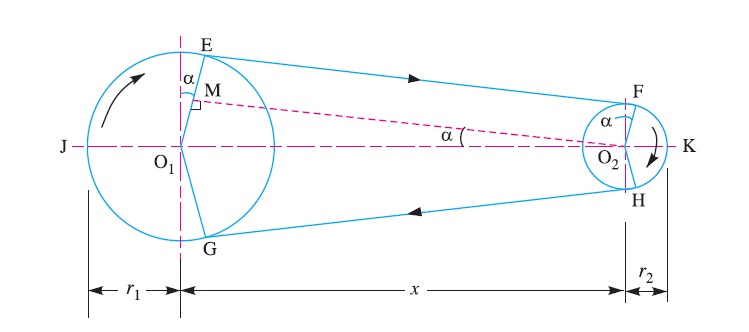
Let r1 and r2 = Radii of the larger and smaller pulleys,
x = Distance between the centres of two pulleys (i.e. O1O2), and
L = Total length of the belt.
Let the belt leaves the larger pulley at E and G and the smaller pulley at F and H as shown in Figure. Through O2 draw O2M parallel to FE.
From the geometry of the figure, we find that O2M will be perpendicular to O1E.
Let the angle MO2O1 = α radians.
We know that the length of the belt,
L = Arc GJE + EF + Arc FKH + HG
= 2 (Arc JE + EF + Arc FK) ……………………..(i)
From the geometry of the figure, we also find that
Sin α = O1M/O1O2 = O1E – EM / O1O2 = r1 – r2 / x
Since the angle α is very small, therefore putting
sin α = α (in radians) = r1 – r2 / x …………………….(ii)
∴ Arc JE = r1 (π/2 + α) ………………………….(iii)
Similarly, arc FK = r2 (π/2 – α) ……………………..(iv)
And EF = MO2 = [(O1O2)2 – (O1M)2]0.5
= [x2 – (r1 – r2)2]0.5
= x [1 – {(r1-r2) /x }2 ]0.5
Expanding this equation by binomial theorem, we have
EF = x [1 – {0.5 {(r1 – r2)/x} + …] = x – (r1 – r2)2 /2x …………………..(v)
Substituting the values of arc JE from equation (iii), arc FK from equation (iv) and EF from equation (v) in equation (i), we get
L = 2 [r1(π/2 +α) + x – {(r1-r2)2/2x} + r2(π/2 -α)]
= 2 [{r1 × π/2} + {r1×α} + x – {(r1- r2)2/2x} + {r2 × π/2} - {r2×α}]
= 2 [π/2(r1+r2) + α(r1-r2) +x – {(r1-r2)2/2x}]
= π(r1+r2) + 2α(r1-r2) +2x – {(r1-r2)2/x}
Substituting the value of α = (r1-r2)/x from equation (ii), we get
L = π(r1+r2) + 2{(r1-r2)/x}{(r1-r2)} +2x – {(r1-r2)2/x}
= π(r1+r2) + 2{(r1-r2)2/x} + 2x – {(r1-r2)2/x}
= π (r1 + r2) + 2x + (r1 – r2 )2 /x ……………. (in terms of pulley radii)
= π/2 (d1 + d2) + 2x + (d1 – d2)2 /4x …… (in terms of pulley diameters)
Length of cross belt drive:
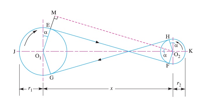
We have discussed that in a cross belt drive, both the pulleys rotate in the opposite directions as shown in Fig
Let r1 and r2 = Radii of the larger and smaller pulleys,
x = Distance between the centres of two pulleys (i.e. O1O2 ), and
L = Total length of the belt.
Let the belt leaves the larger pulley at E and G and the smaller pulley at F and H as shown in Figure.
Through O2 draw O2M parallel to FE.
From the geometry of the figure, we find that O2M will be perpendicular to O1E.
Let the angle MO2O1 = α radians.
We know that the length of the belt,
L = Arc GJE + EF + Arc FKH + HG
= 2 (Arc JE + FE + Arc FK) …………………(i)
From the geometry of the figure, we find that
Sin α = O1M/O1O2 = (O1E + EM)/O1O2 = r1+r2 / x
Since the angle α is very small, therefore putting sin α = α (in radians = r1+r2 / x ………………………….…(ii)
Arc JE = r1 (π/2 + α) ………………. ……(iii)
Similarly, arc FK = r2 (π/2 + α) …………………(iv)
EF = MO2 = [(O1O2 )2 – (O1M)2]0.5
= [x2 – (r1 + r2 )2]o.5
= x [1- (r1+r2 /x )2 ]0.5
Expanding this equation by binomial theorem, we have
EF = x [1- 1/2(r1+r2 /x)2 + …] = x – [(r1+r2)2/2x] ……………………(v)
Substituting the values of arc JE from equation (iii), arc FK from equation (iv) and EF from equation (v) in equation (i), we get,
L = 2 [r1(π/2 +α) + x – {(r1+r2)2/2x} + r2(π/2 +α)]
= 2 [{r1 × π/2} + {r1×α} + x – {(r1+r2)2/2x} + {r2 × π/2} + {r1×α}]
= 2 [π/2(r1+r2) + α(r1+r2) +x – {(r1+r2)2/2x}]
= π(r1+r2) + 2α(r1+r2) +2x – {(r1+r2)2/x}
Substituting the value of α = (r1+r2)/x from equation (ii), we get
L = π(r1+r2) + 2{(r1+r2)/x}{(r1+r2)} +2x – {(r1+r2)2/x}
= π(r1+r2) + 2{(r1+r2)2/x} + 2x – {(r1+r2)2/x}
= π (r1+r2) + 2x + (r1+r2)2 /x …………… (In terms of pulley radii)
= π/2(d1+d2) +2x + (d1 + d2)2/ 4x …………(in terms of pulley diameters)
Velocity ration for simple and compound belt drive:
It is the ratio between the velocities of the driver and the follower or driven. It may be expressed, mathematically, as discussed below:
Let d1 = Diameter of the driver,
d2 = Diameter of the follower,
N1 = Speed of the driver in r.p.m.,
N2 = Speed of the follower in r.p.m.,
∴ Length of the belt that passes over the driver, in one minute
= π d1 N1
Similarly, length of the belt that passes over the follower, in one minute
= π d2 N2
Since, the length of belt that passes over the driver in one minute is equal to the length of belt that passes over the follower in one minute, therefore
= π d1 N1 = π d2 N2
And velocity ratio,
= N2/N1 = d1/d2
When thickness of the belt (t) is considered, then velocity ratio,
= N2/N1 = (d1 + t)/ (d2 + t)
The velocity ratio of a belt drive may also be obtained as discussed below:
We know that the peripheral velocity of the belt on the driving pulley,
ν1 = (π d1 N1)/60, m/s
And peripheral velocity of the belt on the driven pulley,
ν2 = (π d2 N2)/60, m/s
When there is no slip, then ν1 = ν2.
(π d1 N1)/60 = (π d2 N2)/60
N2/N1 = d1/d2
In case of a compound belt drive, the velocity ratio is given by
= N4/N1 = (d1 × d3)/(d2 × d4)
= Speed of last driven / Speed of first driver = Product of diameters of drivers / Product of diameters of driven
Centrifugal tension:
The belt continuously runs over the pulleys, therefore, some centrifugal force is caused, whose effect is to increase the tension on both the tight as well as the slack sides. The tension caused by centrifugal force is called centrifugal tension.
At lower belt speeds (less than 10 m/s), the centrifugal tension is very small, but at higher belt speeds (more than 10 m/s), its effect is considerable and thus should be taken into account.
Consider a small portion PQ of the belt subtending an angle dθ at the centre of the pulley, as shown in FIG
.
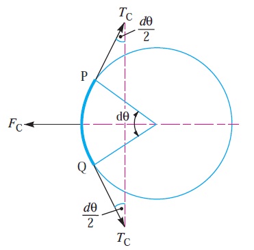
Let m = Mass of belt per unit length in kg,
v = Linear velocity of belt in m/s,
r = Radius of pulley over which the belt runs in metres, and
TC = Centrifugal tension acting tangentially at P and Q in newton’s.
We know that length of the belt PQ
= r.dθ
and mass of the belt PQ = m.r.dθ
∴ Centrifugal force acting on the belt PQ,
FC = m.r.dθ × v2/r
= m.dθ.v2
The centrifugal tension TC acting tangentially at P and Q keeps the belt in equilibrium. Now resolving the forces (i.e. centrifugal force and centrifugal tension) horizontally, we have
Tc sin (dθ/2) + Tc sin (dθ/2) = Fc = = m.dθ.v2
Since the angle dθ is very small, therefore putting sin (dθ/2) = (dθ/2) in equation (i), we have
2Tc (dθ/2) = m.dθ.v2
Tc = m.v2
When centrifugal tension is taken into account, then total tension in the tight side,
Tt1 = T1 + Tc
And total tension in the slack side,
Tt2 = T2 + Tc
2. Power transmitted,
P = (Tt1 – Tt2) v …………………….(in watts)
= [(T1 + Tc) – (T2 + Tc)]v = (T1 – T2) v ……… (same as before)
we see that the centrifugal tension has no effect on the power transmitted.
The ratio of driving tensions may also be written as
2.3 log (Tt1-Tc / Tt2-Tc) = μ.θ
Where,
Tt1 = Maximum or total tension in the belt.
Maximum power transmitted:
Let T1 = Tension on tight side
T2 = Tension on slack side
v = Linear velocity of belt
Then the power transmitted can be given by the equation
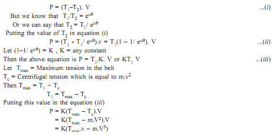
Power transmitted will be maximum if d (P)/dv = 0
Thus differentiating equation with respect to V and equating to zero for maximum power, we get

Equation (iv) gives velocity of belt at which maximum power is transmitted.
From equation (iv) Tmax =3Tc ...(v)
Hence when power transmitted is maximum, the centrifugal tension would be around 1/3rd of the maximum tension.
We know that Tmax = T1 + Tc

Hence condition for transmission of maximum power is:
Tc = 1/3 Tmax, and
T1 =2/3Tmax ...(viii)The net driving tension in the belt = (T1 - T2)
Chain drive
We have seen in belts that slipping is occurs. In order to avoid slipping steel chains are used. The chain are made up of rigid links which are hinged together in order to provide the necessary flexibility for wrapping around the driving and driven wheel. The tooth wheels are known as sprocket wheels or simple sprockets.
A chain drive is a mechanically operating system where we used different types of chains to transmit the power or for movement of something.
Generally, a chain drive is used where the distance between the power produced and where it to be transferred is less, however, this is not applicable for all. In some cases, we can use a chain drive for longer distances power transfer.In belt or rope drive we see there is some percent of slip occurs, but in the chain, there will be no slip. But this does not mean that 100% power is transmitted from one to another device due to friction loss some amount of power loss we can generally see.
![Chain Drives: 5 Types of Chains [Advantages/Disadvantages]](https://glossaread-contain.s3.ap-south-1.amazonaws.com/epub/1643283504_6263065.jpeg)
In chain drive, the speed ratio remains constant which is a major advantage of chain drive and here there is no slippage and in case of belt drive, there is slippage so speed ratio changes as per slippage. A chain is made by a number of links and those are connected by the help of a pin.
Chains are run over a wheel named sprocket which has several amounts of teeth around the circumference of that to grip the chain, however, not all the chains need that sprocket to run over
Types of Chains:
In the field of Mechanical Engineering chains drive can be classified into three broad categories and those are:
- Hoisting Chains
- Conveyor Chains
- Power transmission Chains.
1) HOISTING CHAINS:
A hoist is a mechanical device which is used to lift a load or lowering a load, it can be used for shifting of some heavy product from one place to another place in a workstation. The chains used in this type of devices is named hoist chain, these chains are quite strong to handle heavyweight.
Hoist chains can be classified into two categories:
- Oval-Link Chains.
- Stud-Link Chains.
i) Oval-Link Chains:
It is one of the common types of chain used in hoist; it consists of many oval links attached to each other. These types of chains are also called Coil Chains. Links of this type of chain is oval. However, there are square link types of chains that are also available, but the kinking is occurred easily due to high loading.
Ii) Stud-Link Chains:
The stud-link chains used to minimize the deformation and link or tangle easily. In this type of chain, a round bar or stud is used to fit inside the oval-link chains to provide more strength to the chain. The stud-link chains used to minimize the deformation and link or tangle easily. In this type of chain, a round bar or stud is used to fit inside the oval-link chains to provide more strength to the chain. It is used in Ship to up and down the anchor of the ships, and some crane hoist where we need to lift a very high amount of load.
2) CONVEYOR CHAINS:
As the name suggests conveyor chains that means these types of chains are mostly used in the conveyor. The conveyor is a mechanical device system that is used to move the materials from one place to another. This type of chain is well shaped that it can easily run over the sprocket.
Generally, this type of chain is made of malleable cast iron and used in Low-Speed Machinery approx. 2 m/s.
The one major disadvantage of this type of chain is the motion of the chain is not smooth, there are chances of wear and tear out.
Conveyor Chains are categorized into following types:
- Detachable or Hook Joint types Conveyor chain.
- Closed-end pintle type conveyor chain.
- Detachable or Hook Joint types Conveyor chain: Detachable or Hook Joint types Conveyor chains are used in a conveyor where the length between power transmissions is short.
- Closed-end pintle type conveyor chain: This type of chain is consists of a barrel and link and made in a single casting, and then the chain is heat-treated to provide higher strength.
3) POWER TRANSMISSION CHAINS:
You can easily find out by name of the chain that it is used to transmit the power. This type of chain is made of steel and sometimes it heats treated to minimize wear and tear. This type of chain has greater accuracy and can easily run over the sprocket.
INTRODUCTION TO BRAKES:
A brake is defined as a mechanical device, which is used to absorb the energy possessed by a moving system or mechanism by means of friction.
CLASSIFICATION OF BRAKES:
(i) MECHANICAL BRAKES:
Operated by mechanical means such as levers, springs and pedals.
(ii) HYDRAULIC AND PNEUMATIC BRAKES
Operated by fluid pressure such as oil pressure or air pressure.
(iii) ELECTRICAL BRAKES
Operated by magnetic forces and which include magnetic particle brakes, hysteresis brakes and eddy – current brakes.
BLOCK BRAKE WITH SHORT SHOE:
A block brake consists of a simple block, which is pressed against the rotating drum by means of a lever as shown in figure,
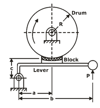
The friction between the block and the brake drum causes the retardation of the drum.
The angle of contact between the block and the brake drum is usually small. When it is less than 45ºC .
The intensity of pressure between the block and brake drum is uniform.
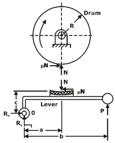
The forces acting on the brake drum,
 ,
,
Where,
Mt = braking – torque (N-mm)
R= radius of the brake drum (mm)
μ=coefficient of friction,
N= normal reaction (N),
Depending upon the magnitude of coefficient of friction and location of hinge pin , there are three different cases:
Case I: a > μc
The friction force helps to reduce the magnitude of the actuating force .
Case II: a = μc
The actuating force is zero. This indicates that no external force is required for the braking action. Such a brake is called a ‘self – locking’ brake.
Case III: a < μc
The actuating force becomes negative.
This is a dangerous operating condition, resulting in uncontrolled braking and grabbing.
BLOCK BRAKE WITH LONG SHOE:
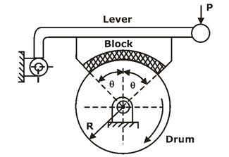
Fig.: Schematic of Long-shoe block brake

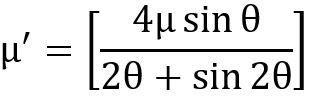
And, θ is the semi – cone angle.
SIMPLE BAND BRAKES:
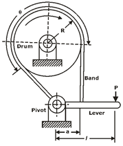
The working of the steel band is similar to that of a flat belt operating at zero velocity.
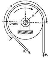
Fig.: FBD of band
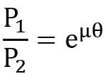
Torque absorbed by the brake is given by,

DIFFERENTIAL BAND BRAKES:
- When neither end of the steel band passes through the fulcrum of the actuating lever, the brake is called the differential band brake.
The free – body diagram of forces acting on the band and the lever is shown in figure,
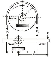
Fig.: FBD of Differential band brake
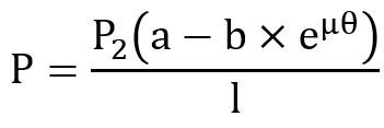
For the self – locking condition,

DISK BRAKES:
A disk brake is similar to a plate clutch, except that one of the shafts is replaced by a fixed member.
Advantages of disk brakes
- Disk brake is simple to install and operate
- Disk brake has high torque transmitting capacity in small volume
- The brake can never become self – locking
INTRODUCTION TO CLUTCH:
The clutch is a mechanical device, which is used to connect or disconnect the source of power from the remaining parts of the power transmission system at the will of the operator.
CLASSIFICATION OF CLUTCH:
(i) Positive Contact Clutches:
- They include square jaw clutches, spiral jaw clutches and toothed clutches.
(ii) Friction Clutches:
- They include single and multi-plate clutches, cone clutches and centrifugal clutches.
(iii) Electromagnetic Clutches:
- They include magnetic particle clutches, magnetic hysteresis clutches and eddy current clutches.
(iv) Fluid Clutches:
- Power transmission is achieved by means of hydraulic pressure.
TORQUE TRANSMITTING CAPACITY OF SINGLE-PLATE CLUTCH:
A friction disk of a single plate clutch is shown in figure,
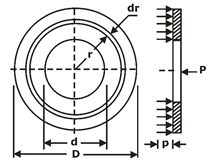
Notations used
D= Outer diameter of friction disk (mm)
d = inner diameter of friction disk (mm)
P= intensity of pressure at radius (mm)
F= total operating force (N)
Mt = torque transmitted by the clutch (N-mm)
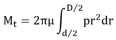
Two theories are used to obtain the torque capacity of the clutch.
They are called uniform pressure theory and uniform wear theory.
UNIFORM PRESSURE THEORY:
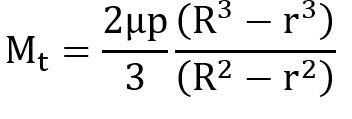
In case of new clutches employing a number of springs, the pressure remains constant over the entire surface area of the friction disk.
UNIFORM WEAR THEORY:
It is assumed that the wear is uniformly distributed over the entire surface area the friction disk.
When the wear is uniform,
P r=Constant
In this case, P is inversely proportional to r Therefore, pressure is maximum at the inner radius and minimum at the outer periphery.


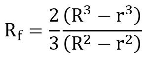
For uniform wear theory or worn – out clutches:

For uniform pressure theory or new clutches:
Note:
Number of disks = number of pairs of contacting surfaces+1=Z+1
Suppose,
Z1= number of disks on driving shaft
Z2 = number of disks on driven shaft
Z1 +Z2 = number of pairs of contacting surfaces + 1
Or number of pairs of contacting surfaces Z1 +Z2 –1
CONE CLUTCHES:
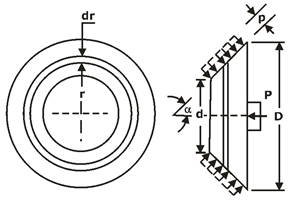
Fig.: Analysis of cone clutch
In case of uniform pressure theory,

In case of uniform wear theory,

Where, α is the semi cone angle.
Centrifugal clutch:
It consists of number of shoes on the inside of a rim of the pulley. The outer surface of the shoes is covered with a friction material.
These shoes, which can move radially in guides, are held against the boss on the driving shaft by means of spring.
The springs exert a radially inward force which is assumed constant.
The torque transmitting capacity of the clutch is given by,

Notations used
rg = radius of the drum (mm)
rd = radius of the centre of gravity of the shoe in engaged position (mm)
m= mass of each shoe
Pcf = centrifugal force (N)
Ps = spring force (N)
z= number of shoes
ω2 =running speed (rad/s)
ω1= speed at which engagement starts (rad/s)