UNIT 3
Electronics Instruments
Digital Multimeter :
- A Multi meter the most common measuring instrument. The name comes from multiple meter. There are two common types of Multi meter.
- The multimeter (DMMs) are the most common Measurement readings are displayed as numerical values on the LCD display. The display also alerts you to any pertinent symbols and warning.
- Digital meters on the other hand offer high accuracy have a high i/p impedance and are smaller in site.

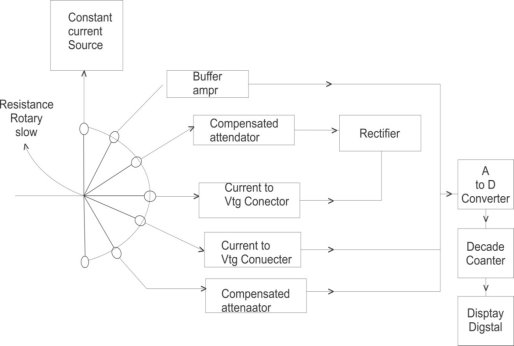
An instrument which is capable of measuring a.c. And d.c voltages a.c and d.c. current and resistances over several range is called digital multimeter. The various measurement possible by DMM are resistance a.c voltage and current d.c voltage and current. The selection of the parameter is possible with the help of rotary switch connected to i/p probes of DMM.
- Resistance Measurement : The rotary switch is in position 1 and resistance is connected to input probes. The constant current source Drives a current through unknown resistance. This produces Vtg across resistance which is directly proportional to the resistance. It is given to the buffer amplify and then to analog to digital converter. The ADC converts it to equivalent digital signal and it is displayed with the help of digital display a.c voltage measurement : The rotary switch is in position 2 and i/p a.c vtg is applied to probes if it is above the selected range it is attenuated with the help of compensated attenuator It is rectified to produce proportional d.c vtg then it is given to ADC which display it in volts
- A.c current measurement : the rotary switch is in position 3 and unknown current is applied across i/p probes it is converted to proportional vtg using current to vtg convertors

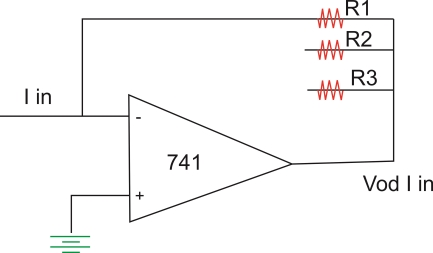
This I V converter is op-amp circuit as shown above. The op-amp/p current is zero hence I in flows through R1 and drop across R1osVo hence vtg o/p  the resistance R1 R2 and R3 are used for the proper range selection. This vtg is rectified and then given to ADC which displays the current in amperes.
3. D.c current measurement : The rotary switch is in position 4 and unknown d.c current is applied across i/p probes this vtg is given to ADC without rectification as this is proportional to d.c current ADC display it in amperes on digital display.
4. D.C voltage measurement : The rotary switch is in position 5 and unknown vtg is applied across i/p probes it is attenuated and directly given to ADC display it in volts.
Specifications of Digital Multimeter :
- D.C Voltage : this includes various d.c vtg ranges available along with the resolution and accuracy
- A.c Voltage : this includes various a.c vtg ranges available along with the resolution and accuracy.
- A.C current : this includes various a.c current ranges available along with the resolution and accuracy.
- Resistance : this includes the available resistance range typical six range are available from 200Ω to 20 MΩ the accuracy is
 0.1% of reading + two digits + 0.002Ω on the lowest range.
 - Input Impedance : The i/p Impedance is about 10 MΩ on all the range
- Normal mode noise rejection : this indicates the ability of the meter
It is greater than 60 dB at 50 HZ while the common mode noise rejection is greater than 90 dB at 50 HZ and greater than 120 dB at d.c
7. Overload protection : The overload protection of 1000 V d.c and 75 0ɤ.m.s. a.c is provided.
8. Diode test : The vtg drop across the diode can be measured for which 1 mA + 10% of constant current source is used.
9. Conductance : It can display Conductance in siemens
10. Relative Reference : when RF1 button is pressed the displayed reading is stored as a reference and then subtracted from the subsequent readings to indicate only amount of deviation from the reference.
11. Frequency : The frequency ranges is 200HZ to 200 kHZ auto selection.
Oscilloscope is an electronic equipment, which displays a voltage waveform. Among the oscilloscopes, Cathode Ray Oscilloscope (CRO) is the basic one and it displays a time varying signal or waveform.
In this chapter, let us discuss about the block diagram of CRO and measurements of some parameters by using CRO.
Block Diagram of CRO
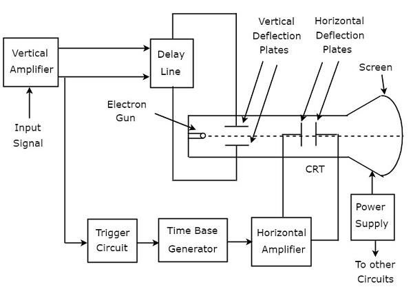
Cathode Ray Oscilloscope (CRO) consists a set of blocks. Those are vertical amplifier, delay line, trigger circuit, time base generator, horizontal amplifier, Cathode Ray Tube (CRT) & power supply. The block diagram of CRO is shown in below figure.

The function of each block of CRO is mentioned below.
- Vertical Amplifier − It amplifies the input signal, which is to be displayed on the screen of CRT.
- Delay Line − It provides some amount of delay to the signal, which is obtained at the output of vertical amplifier. This delayed signal is then applied to vertical deflection plates of CRT.
- Trigger Circuit − It produces a triggering signal in order to synchronize both horizontal and vertical deflections of electron beam.
- Time base Generator − It produces a sawtooth signal, which is useful for horizontal deflection of electron beam.
- Horizontal Amplifier − It amplifies the sawtooth signal and then connects it to the horizontal deflection plates of CRT.
- Power supply − It produces both high and low voltages. The negative high voltage and positive low voltage are applied to CRT and other circuits respectively.
- Cathode Ray Tube (CRT) − It is the major important block of CRO and mainly consists of four parts. Those are electron gun, vertical deflection plates, horizontal deflection plates and fluorescent screen.
The electron beam, which is produced by an electron gun gets deflected in both vertical and horizontal directions by a pair of vertical deflection plates and a pair of horizontal deflection plates respectively. Finally, the deflected beam will appear as a spot on the fluorescent screen.
In this way, CRO will display the applied input signal on the screen of CRT. So, we can analyse the signals in time domain by using CRO
Measurements by using CRO
We can do the following measurements by using CRO.
- Measurement of Amplitude
- Measurement of Time Period
- Measurement of Frequency
Measurement of Amplitude
CRO displays the voltage signal as a function of time on its screen. The amplitude of that voltage signal is constant, but we can vary the number of divisions that cover the voltage signal in vertical direction by varying volt/division knob on the CRO panel. Therefore, we will get the amplitude of the signal, which is present on the screen of CRO by using following formula.
A=j×nv
Where,
A is the amplitude
j is the value of volt/division
Nv is the number of divisions that cover the signal in vertical direction.
Measurement of Time Period
CRO displays the voltage signal as a function of time on its screen. The Time period of that periodic voltage signal is constant, but we can vary the number of divisions that cover one complete cycle of voltage signal in horizontal direction by varying time/division knob on the CRO panel.
Therefore, we will get the Time period of the signal, which is present on the screen of CRO by using following formula.
T=k×nh
Where,
T is the Time period
j is the value of time/division
Nv is the number of divisions that cover one complete cycle of the periodic signal in horizontal direction.
Measurement of Frequency
The frequency, f of a periodic signal is the reciprocal of time period, T. Mathematically, it can be represented as
f=1/T
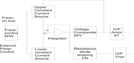
The function generator is an instrument which generates different types of wave form The most required common wave forms are sine wave, saw tooth wave, triangle wave, square wave and these various outputs of the generator are available simultaneously. The purpose of providing simultaneously waves is fulfilled by the function generator In function generator the o/p waveform can be generated at a desired freq in range from few hertz to several kilohertz. In the function generator the freq is controlled which drives the integrator. The freq controlled vtg is used to regulate two current source namely upper current source and lower current source. The upper current source supplies constant current to an integrator. The o/p vtg of integrator then increases linearly with time. If the current charging the capacitor increases or decreases the slope of o/p vtg increases or decreases respectively. Hence this controls freq.

Block diagram of function generator
- The voltage comparator multi vibrator circuit changes the state of the n/w when the o/p vtg of integrator equals the maximum predetermined upper level.
- Because of this change in state the upper current source is removes and the lower current source is switched on
- This lower current source supplies opposite current to the integrator or ckt. The o/p of integrator decreases linearly with time when this o/p vtg equals maximum predetermine upper level on –ve side the comparator multi vibrator again changes the condition of the n/w by switching off the lower current source and switching on the upper current source
- The o/p vtg of the integrator has triangular wave form
- The freqn of this triangular wave form is determined by the upper current source and lower current source
- To get square wave the o/p of the integrator is passed through comparator.
- The vtg comparator delivers square wave o/p vtg of same freqn as that of i/p triangular wave form
- The sine wave is derived from triangular wave. The triangular wave is synthesised in to sine wave using diode resistance n/w in this shaper ckt , the slope of triangular wave is changed as it amplitude changes. This result in a sine wave with less than 1% distortion
- The two o/p amplifiers provide two simultaneous individually selected o/p of any of the wave form functions.
Application :
- It is used to generate different types of wave form simultaneous such as sine wave, square wave, triangular wave & saw tooth wave at a desired freqn from few hertz to several kilohertz.
- It is used to test bandwidth of audio freq ampɤ using square wave testing method
- It can be used in trouble shooting of various Analogas well as digital instruments.
- It is most extensively used as signal source for radio receiver alignment procedure.