UNIT 5
Communication System

Fig. 1 Block diagram of elements of communication (ref 3)
Information Source
It produces a message that is analog in nature, i.e., the output of the information source is a continuous signal.
Analog carrier source
Sine wave is used as a carrier signal which will help in analog modulation.
Analog modulation
The carrier signal is superimposed with the message signal and then the modulated signal is obtained which is also analog in nature.
Communication channel
The analog modulated signal is transmitted via the communication channel towards the receiver end after addition of the requisite power levels.
Analog demodulation
At the receiver end, the incoming modulated signal is passed through an analog demodulation process which extracts the analog message signal. The analog message is then passed onto the final destination.
Destination
The nature of signal starting from the information source till the final destination is analog.
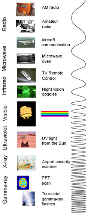
1>. Antenna height reduces
2>. Avoids mixing of signal
3>. Increases the range of communication [ In Kilometers]
4>. Multiplexing of signals is possible
5>. Improves quality of reception of signal.
Modulation Techniques :-
AM :-“ The process of changing the amplitude of the carrier wave as per the intensity [ amplitude ] of the modulating signal is called as Amplitude Modulation “.
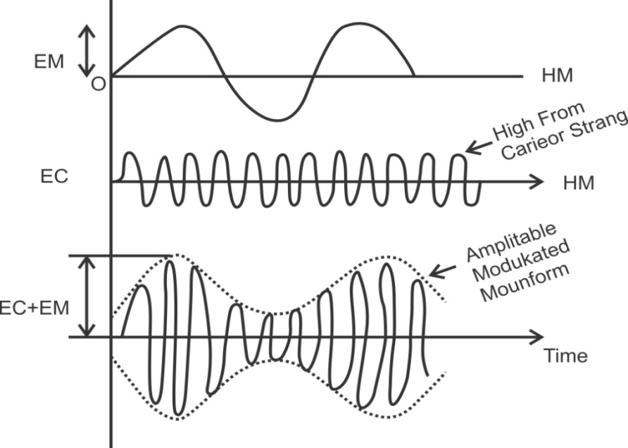
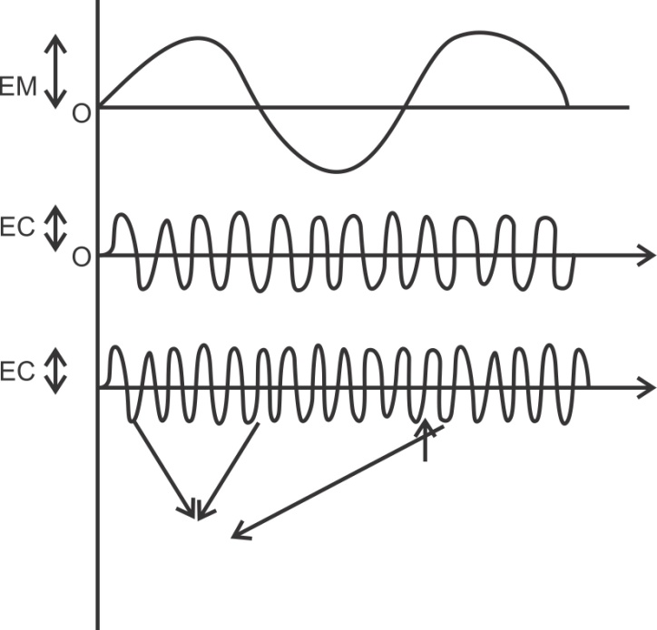
FM :- “ In freqn modulation the freqn of a carrier signal is varied by the modulating signal “.
“ The process of changing the freqn of the carrier wave according to the intensity [ amplitude ] of the modulating signal is called as freqn modulation “.
Comparison AM &FM :-
Sr No | A.M. | F.M. |
1>. | Amplitude of carrier is charged in accordance with amplitude of modulating signal. | Freqn of carrier is change in accordance with amplitude of modulating signal. |
2>. | Freqn is constant | Amplitude is constant |
3>. | The AM signal is given as, XAM (t) = Ac [ 1 + m x(t)] Cos (wct) | The FM signal is given as XFM (t) = Ac [ Cos (wct) + 2 ∏ Kf x(t)] |
4>. | Modulation index of AM, M = Am / Ac | Modulation index of FM, Βf = Δf / fm, where Δf = Am Kf
|
5>. | BW = 2 fm. Bandwidth of AM is 2W where W is bandwidth of modulating signal & 2fm is for single tone modulation. | Bandwidth of FM is BT = 2 ( βf + 1 )W, where W is bandwidth of modulating signal. For single tone modulation BW = 2 ( Kf Am + fm ) |
6>. | Requires small bandwidth compared to FM. | Required large BW compared to AM. |
7>. | It has only two sidebands for single tone modulation. | It has infinite sidebands even for single tone moduln. |
8>. | It is not suitable for high quality music broadcasting. | It is suitable for high quality music broadcasting. |
9>. | Noise immunity is low | It has better noise immunity than AM. |
10>. | It is suitable for long distance transmission | It is suitable for line of sight transmission. |
11>. | Used in MW, SW broadcasting, video transmission in T.V. | It is used in high quality music broadcasting audio broadcasting in T.V. |
12>. | Cannot reject interfering signals in the same band. | Can reject interfering signals in the same band due to capture effect. |
13>. | Transmission efficiency is poor due to use of Class A & amplifiers. | Transmission efficiency is better due to use of Class C ampr. |
PM:
Pulse Amplitude Modulation
In Pulse Amplitude Modulation (PAM) technique, the amplitude of the pulse carrier varies, which is proportional to the instantaneous amplitude of the message signal.
The pulse amplitude modulated signal will follow the amplitude of the original signal, as the signal traces out the path of the whole wave. In natural PAM, a signal sampled at Nyquist rate can be reconstructed, by passing it through an efficient Low Pass Filter (LPF) with exact cutoff frequency.
The following figures explain the Pulse Amplitude Modulation.
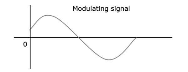

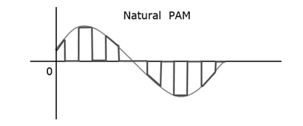
Though the PAM signal is passed through a LPF, it cannot recover the signal without distortion. Hence, to avoid this noise, use flat-top sampling. The flat-top PAM signal is shown in the following figure.
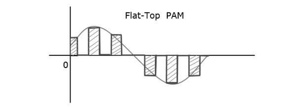
Flat-top sampling is the process in which, the sampled signal can be represented in pulses for which the amplitude of the signal cannot be changed with respect to the analog signal, to be sampled. The tops of amplitude remain flat. This process simplifies the circuit design.
Pulse Width Modulation
In Pulse Width Modulation (PWM) or Pulse Duration Modulation (PDM) or Pulse Time Modulation (PTM) technique, the width or the duration or the time of the pulse carrier varies, which is proportional to the instantaneous amplitude of the message signal.
The width of the pulse varies in this method, but the amplitude of the signal remains constant. Amplitude limiters are used to make the amplitude of the signal constant. These circuits clip off the amplitude to a desired level, and hence the noise is limited.
The following figure explains the types of Pulse Width Modulations.
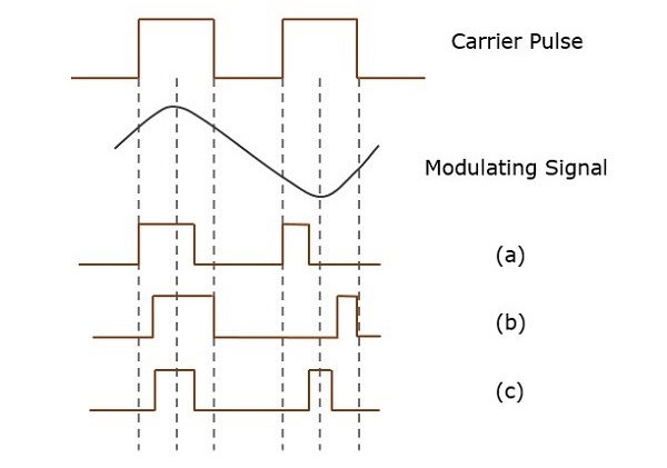
There are three types of PWM.
- The leading edge of the pulse being constant, the trailing edge varies according to the message signal. The waveform for this type of PWM is denoted as (a) in the above figure.
- The trailing edge of the pulse being constant, the leading edge varies according to the message signal. The waveform for this type of PWM is denoted as (b) in the above figure.
- The center of the pulse being constant, the leading edge and the trailing edge varies according to the message signal. The waveform for this type of PWM is denoted as (c) shown in the above figure.
Pulse Position Modulation
Pulse Position Modulation (PPM) is an analog modulation scheme in which, the amplitude and the width of the pulses are kept constant, while the position of each pulse, with reference to the position of a reference pulse varies according to the instantaneous sampled value of the message signal.
The transmitter has to send synchronizing pulses (or simply sync pulses) to keep the transmitter and the receiver in sync. These sync pulses help to maintain the position of the pulses. The following figures explain the Pulse Position Modulation.
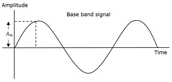
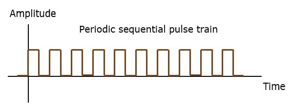
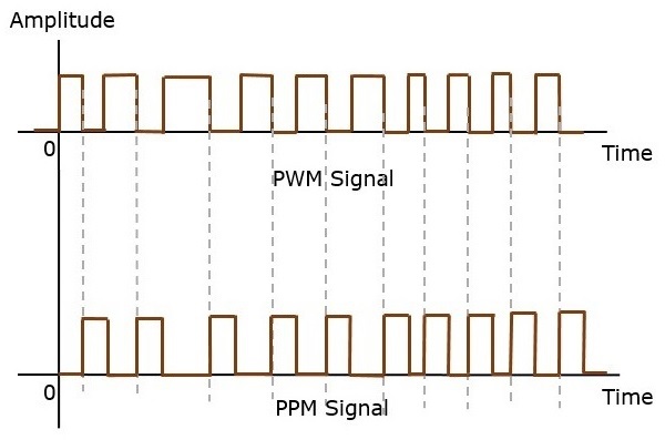
Pulse position modulation is done in accordance with the pulse width modulated signal. Each trailing edge of the pulse width modulated signal becomes the starting point for pulses in PPM signal. Hence, the position of these pulses is proportional to the width of the PWM pulses.
Advantage
As the amplitude and the width are constant, the power handled is also constant.
Disadvantage
The synchronization between the transmitter and the receiver is a must.
Comparison between PAM, PWM, and PPM
The following table presents the comparison between three modulation techniques.
PAM | PWM | PPM |
Amplitude is varied | Width is varied | Position is varied |
Bandwidth depends on the width of the pulse | Bandwidth depends on the rise time of the pulse | Bandwidth depends on the rise time of the pulse |
Instantaneous transmitter power varies with the amplitude of the pulses | Instantaneous transmitter power varies with the amplitude and the width of the pulses | Instantaneous transmitter power remains constant with the width of the pulses |
System complexity is high | System complexity is low | System complexity is low |
Noise interference is high | Noise interference is low | Noise interference is low |
It is similar to amplitude modulation | It is similar to frequency modulation | It is similar to phase modulation |
AM TRANSMITTER
AM transmitter generates high power and its primary requirement is efficiency.
Here, AM is produced is of very low power.
Although the methods of generating AM described here relate to both applications and emphasis will be put on methods of generating high powers.
In an AM transmitter, amplitude modulation can be generated at any point after the radio frequency source.
Actually, even a crystal oscillator could be amplitude modulated, except that this would be an unnecessary interference with its frequency stability.
lf the output stage in a transmitter is collector modulated in a low power transmitter, the system is called high level modulation.
lf modulation is applied at any other point, including some other electrode of the output amplifier, then so called low level modulation is produced.
Naturally, the end product of both systems is the same, but the transmitter circuit arrangements are different .
The higher the level of modulation, the larger the audio power required to produce modulation.
The higher-level system is a disadvantage in this regard.
On the other hand, the output stage is modulated, each following stage must handle a sideband power as well as the carrier.
All these subsequent amplifiers must have sufficient bandwidth for the sideband frequencies.
Each of the systems have one great advantage i.e. low modulating power requirements in one case, and much more efficient RF amplification with simpler circuit design in the other.
lt is found that a collector modulated class C amplifier tends to have better efficiency, lower distortion and much better power-handling capabilities than a base-modulated amplifier. Because of these considerations, broadcast AM transmitters today almost invariably use high-level modulation.
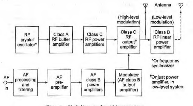
Fig. AM Transmitter (ref 3)
AM Receiver :-

Fig. Superheterodyne AM receivers (ref 3)
The signal is received by the RF amplifier which is a wideband class A amplifier whose resonant frequency response curve can be tuned from 540 kHz to 1650 kHz .
The modulated signal is amplified and fed to the mixer stage which is a class C circuit capable of producing the sum, difference, and original frequencies, and which receives signals from two sources namely the RF amplifier and the local oscillator.
The unmodulated signal from the local oscillator is further fed to the mixer where simultaneously it is mixed with the modulated signal received from the RF amplifier.
The local oscillator (LO) is a tunable circuit with a tuning range that extends from 995 kHz to 2105 kHz.
The output from the mixer circuit is then connected to the intermediate frequency amplifier (IF amp) which amplifies a narrow band of select frequencies (455 kHz± 3 kHz).
In some receivers this class A circuit acts not only as an amplifier but also as a filter for unwanted frequencies which would interfere with the selected one.
This new frequency contains the same modulated information as that transmitted from the source but at a frequency range lower than the standard broadcast band.
This process helps to reduce the unwanted interference from outside sources.
The signal is further rectified and filtered to eliminate one sideband and is finally amplified for listening.
F.M. Transmission :-
A signal is described by its amplitude freqn and phase. Frequency and phase constitute the angle.
In angle modulation the freqn or phase of carrier is varied according to the message / modulating signal.
The method of angle modulation in which freqn of carrier is varied is called freqn modulation ( FM ).
The method of angle modulation in which phase of carrier is varied is called phase modulation ( PM ).
FM is more popular than AM and is useful for high fidelity broadcasting of audio & other applications.
The Advantages of FM are :
1>. It has better noise immunity
2>. The performance of FM is better at low power
3>. Transmission bandwidth is not affected by msg signal bandwidth.
The Disadvantages of FM are :
P.M. & F.M. Are nonlinear modulation techniques. Hence the analysis of angle modulation is complex and we have to rely on approximate analysis.
Angle modulated signal theoretically has infinite bandwidth even for band limited signals. Hence we have talk about effective bandwidth. This effective bandwidth is much higher than that required in AM.
F.M. Reception :-
The FM receiver is also a super heterodyne receiver like AM. But following considerations are required for an FM receiver.
1>. The operating frequency of FM is higher compared to AM.
2>. Different detection or demodulation technique will be required for FM.
3>. There will be need for amplitude limiting & de-emphasis in FM.
4>. Different method of obtaining AGC is required.
Mixer Uses colpits &clapp oscillator for VHF range.
If ampr If = 10.7 MHz with BW 200 KHz gain low use two If stages to improve gain.